Gato build has resumed.

Collapse
X
 
  • Time
  • Show
Clear All
new posts
  • Ralph --- SSBN 598
    Junior Member
    • Oct 2012
    • 1417

    #61
    July 23rd ======================

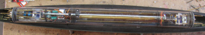
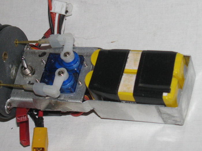
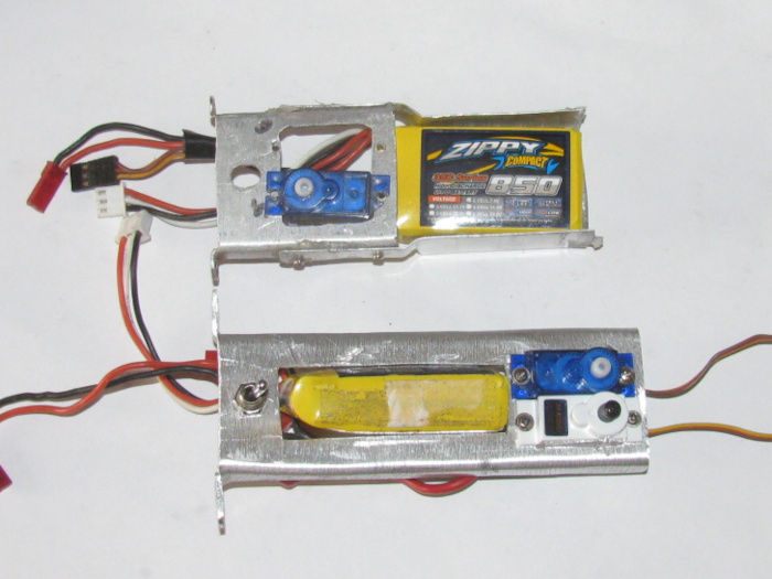
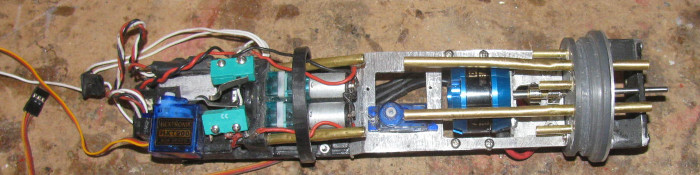
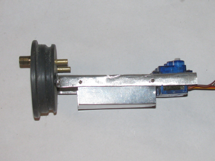
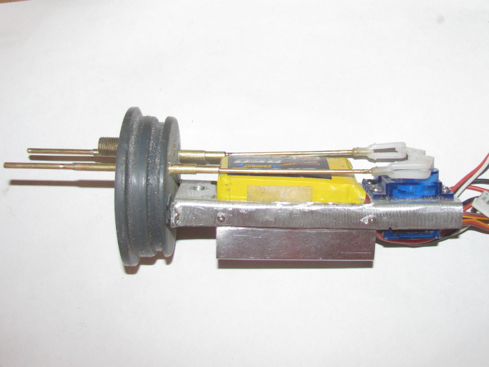
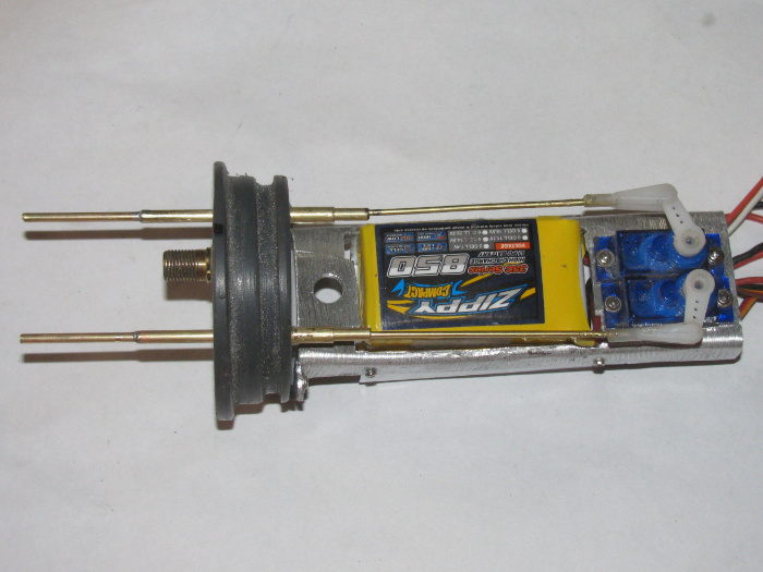
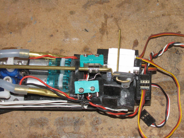
    This morning, I assembled the electronics again to test before putting them in the cylinder.
    Testing went well.
    Everything works.

    Stopped to have something to eat.
    Back out in the shop, I noticed something I had not noticed before.

    The bow planes where not in the up position.
    They were about 1/2" lowered.

    Interesting!
    So I powered up the system and put the bow planes in the full down position. (horizontal to level)
    Turned everything off.
    Did other stuff.
    About 45 minutes later, I noticed the bow planes where up a little more than a 1/2" from level.

    A little thought explained a lot of things.

    I have while building this boat, had several small servos fail.
    1 or 2 because I bumper the rudder or rear planes causing a gear to strip in the servos.
    I have also had to replace several bow plane retract servos.

    Now I can see the issue.
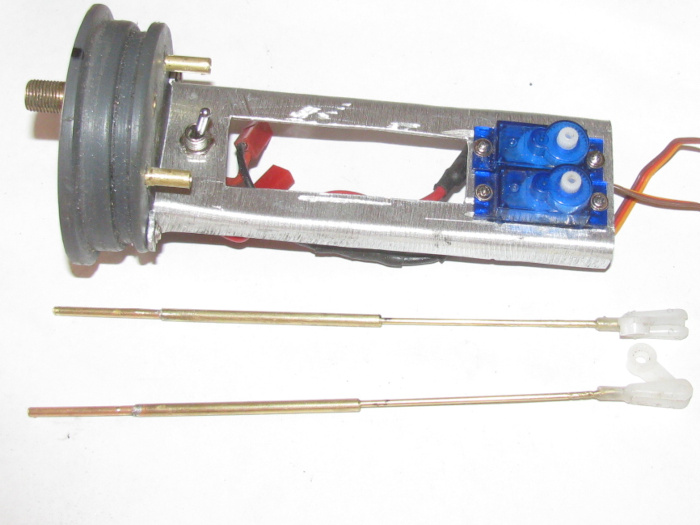
    I used rubber boot seals on the control rods.
    They work well and are easy to install.

    But here is what I think is happening.
    The boots have a natural at rest center.
    When used on the rudder, rear planes and even the bow plane pitch control rods, the servos spend most of their time centered.
    Boot in it's natural state.

    However, the bow planes retract servo is either all the way up or all the way down.
    The rubber boot seal is always under pressure and never sitting at natural.
    This causes pressure on the control rod transferred to the servo.
    The servo when in the up or down position is fighting the natural center of the boot.

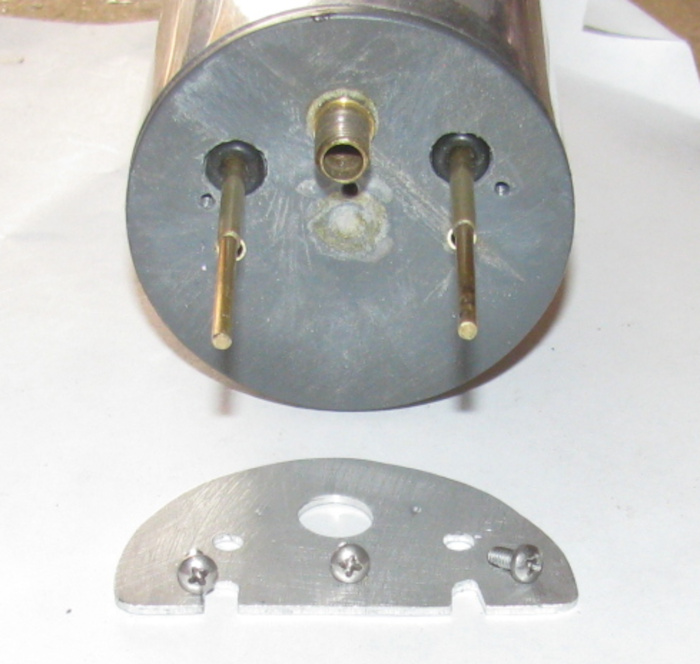
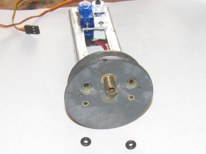
    The fix is to remove the boot seal and use o-rings which have no natural center.

    I have already removed 3 boot seals on the rear cap and now I have removed the 2 boot seals from the front cap.
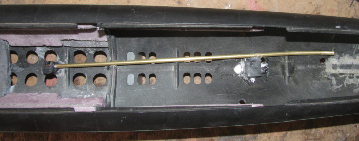
    I have removed the boot through cap tubes.
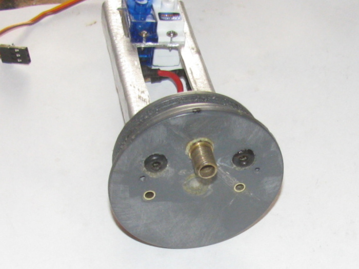
    I have cut the o-ring recesses.
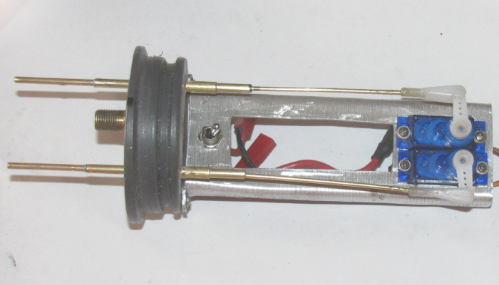
    I have installed the 1/8" brass tubes use to guide the control rods.
    I have modified the control rods with brass tube sleeves to bring the diameter up to 1/8" for the o-rings.
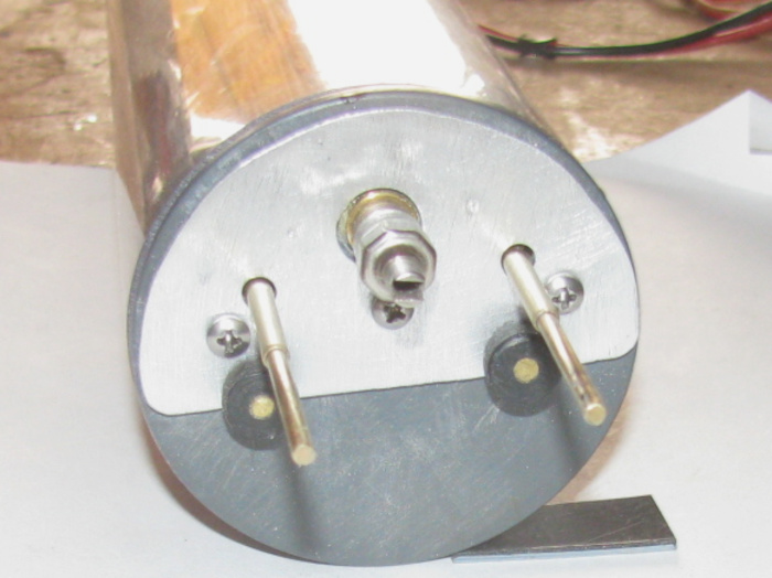
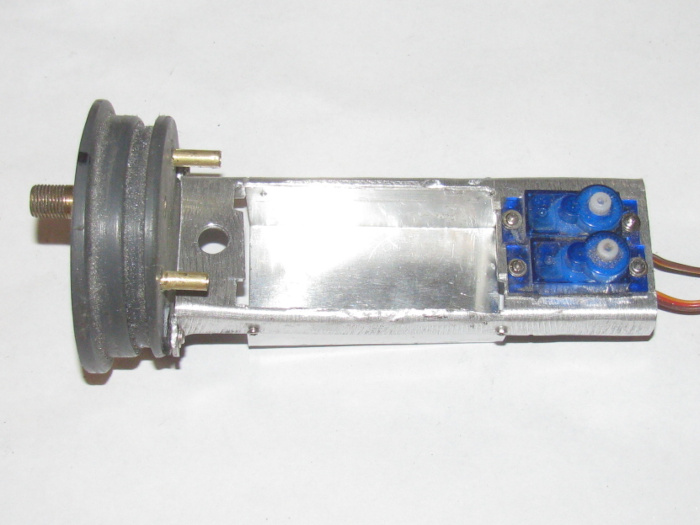
    I am making the aluminum pressure plate that will hold the o-ring down in compression.

    I looked for 1/8" o-rings and need to look some more.
    May have to order some.
    The hardware store has not restocked since I bought them out.
    I can steal a couple of o-rings from the George Washington which is all apart in a bucket at the moment.
    This will keep me moving forward on the Gato.

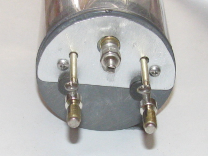
    Control rods going through o-ring seals requires less effort from the servos.

    Back out to the shop to finish making the aluminum pressure plate.
    Only have to find 3 small bolts to hold the plate against the end cap and drill 3 holes and tap.

    Comment

    • Ralph --- SSBN 598
      Junior Member
      • Oct 2012
      • 1417

      #62
      July 24th ======================

      Yesterday was not a good day.
      Felt bad all day.

      Today is better and I made it out to the shop for a little while.

      I fitted the front end cap compression plate.
      Drilled and tapped all the control and mounting bolts holes.

      Here is the end cap with the control rods sticking through and the o-rings in place.
      The Schreader valve body with the insides removed.
      There are 3 holes for the pressure plate bolts.
      They have been threaded..
      There are 2 brass lined holes for he the 2 safety cables. (not sure I need them now)

      The pressure plate and 3 bolts below the end cap.


      Pressure plate installed with 3 bolts.
      Valve cap on.
      The 2 safety cable pins are in place just for show. (black knobs with brass centers)


      Both bow plane retract and bow plane pitch magnet connectors in place.

      Comment

      • Ralph --- SSBN 598
        Junior Member
        • Oct 2012
        • 1417

        #63
        July 25th ======================

        Still not feeling my best.

        Anyway, out to the shop.
        I pulled up my wooden milk crate and sat down.
        I decided to work on both the rear and front electronics trays.

        There is so much wire!
        Servo wires, power wires and wires from the pitch controller and fail safe board.
        Started by pulling the 2 long servo extension wires through the ballast tank brass tube.
        Then the the 2 power wires.
        That makes 8 wires through the ballast tank through tube.

        Next, I worked on the front electronics tray.
        I have wires to 2 servos that are taking up way too much space.
        I wrapped the servo wires around the servos and taped them in place so I had about 1" of wire and plugs to each.
        Then I have wires to both batteries. (parallel)
        The wires are not a big problem but there are 2 connector plugs.
        Long red connector plugs that come on the batteries.
        I folded them until I got them next to the end cap under the tray below the servo control rods.
        There is a electronic control board. (now I am thinking I don't know what it's for)
        Going to have to figure it out.

        On to the rear electronics tray.
        There are 3 servos with all their wires.
        There are 2 switches to operate the 2 air pumps.
        There is main power to the ESC and it's Rx wires.
        There are the 3 motor wires.
        There is a circuit board with it's wires.

        Spent time routing the wires and tie wrapping in place.
        The most important wires where the main motor wires that cross over the spinning motor case. (motor is an out runner)
        I ran the servo plug wires back to the Rx and taped them to the aluminum tray.

        Now, both trays will slide in to the cylinder and nothing touches the cylinder wall.
        The end caps push in to where the cap ledges touch flush all the way around.

        This was enough.
        Temperature has made it to 105F and no wind at all.

        Comment

        • Ralph --- SSBN 598
          Junior Member
          • Oct 2012
          • 1417

          #64
          ======================
          I could not stand it.
          I had to go out and look at the circuit board on the front electronics tray.
          I now know what it is.
          I will have to go to my build notebook to see why I put the Fail Safe circuit on the bow planes.
          I will also have to wire the system up and test it to see if the Fail Safe is on the retract or planes pitch.
          A quick trace of the servo wires tells me it may be the bow plane pitch.
          -------------------------
          Thinking about it, if the signal fails while running submerged, the Fail Safe on the ballast tank air pumps would be of no help.
          They would pump water in to the ballast tanks which are already full.
          The mast that is hooked up to the air pumps would be under water so no air.

          Running under water the boat could stay submerged so having the bow planes Fail Safe in the rise position would bring the air mast up above the surface and the pumps would start pumping air, surfacing the boat.

          If the boat is submerged and the main motor stops, the boat will be trimmed to bring the mast and 1/4" to 1/2" of the conning tower above the surface of the water again allowing the air pumps to pump air.

          This boat basically is a dynamic diver but able to submerge to the top of the conning tower.
          The bow planes will have no problem pushing the boat down below the tower and masts.

          The boat is also setup so if the BEC turns the main motor off, all the other equipment will continue to work.
          This allows the air pumps to work right down to a dead battery.

          I hope the build notebook tells me this is what I did.

          Comment

          • Ralph --- SSBN 598
            Junior Member
            • Oct 2012
            • 1417

            #65
            July 27th ======================

            Feeling a little better.
            Out to the shop.

            With the 2 servo extensions and power wires through the ballast tank, it is now time to install the rear electronics tray in to the cylinder.
            Connect the 2 power wires, then plug in the two servo wires to the Rx.
            Slide tray in to the cylinder and pull the wires out the front of the cylinder to take up slack.

            Before pushing the end cap in to the cylinder, I cleaned the groove and o-ring.
            Greased the o-ring and put it on the end cap.
            Push the end cap in to cylinder and line it up with the indexing marks.

            Next I plugged the power wires to the front electronics tray.
            I have to turn on the Tx and Rx to check which servo wires go to which servo.
            While I am testing, I checked the inlet and outlet air tubes.
            I need to know which is the air from pump to ballast tank.
            Got it.

            Clean o-ring groove and o-ring.
            Grease o-ring and slip on to end cap.

            Now I have to bend or fold the wires back on themselves to get them in the cylinder.
            Push end cap in to cylinder and turn to index marks.

            With the cylinder electronics in place, I can measure for the 2 safety wires.
            Made them up and covered the brass tube connectors with shrink tube this time.d
            I kept getting stuck by the wire ends before.
            This fixes that.

            Cylinder was pressure tested by blowing in to the cylinder through the Shreader valve.
            Holds pressure.
            Next test will be in the water.

            Here is the completed cylinder sitting on the hull.


            The cylinder assembled, I can mark where the air inlet location is.
            And which side it is on.

            I need an air tube to the bottom of the cylinder under a flood hole so the air will go in to the ballast tank.
            On the left side there is the air tube outlet in the center of the ballast tank pin.
            The pin goes up in to the ballast tank through a flood hole.
            Holds the ballast tank in place.

            The right end of the air inlet tube will get a rubber fuel hose that will be glued to the hull side and brought up to where I can bend it to connect to the air outlet end cap tube.

            Need to let the silicone glue holding the brass air tube cure.


            I think this is enough for today.
            It's getting warm and I need to try and get better.

            Comment

            • Ralph --- SSBN 598
              Junior Member
              • Oct 2012
              • 1417

              #66
              July 28th ======================

              Back in the shop.
              I put the assembled cylinder in to the hull.
              I connected the rudder and rear planes magnetic control rods.
              I turned ont he Tx and Rx and went about adjusting the length of the control rods.
              Center the rudder and level the rear planes.

              Move tot he front and the bow plane.
              Connected the magnetic connectors and started adjusting the control rod length.

              Going fine until I moved the retracts from up to down.
              The control rod bond a little over half way down.
              Looking down through the cylinder I see what might be the issue.
              Move the bow planes to center and then worked on the bow plane pitch control rod.
              At center everything is fine but when I moved the planes to up or down, the control rod bond up as did the retract control rod.

              Looking through the cylinder I see the same issue with the pitch control rod.
              Removed the safety cables.
              Pulled the front end cap off with the electronics tray.
              Here is the electronics tray without the Fail Safe board which sits on top of the batteries.


              The issue is the distance from the end cap control rod bushing to the servo.
              The swing of the servo at center is fine but at either end the control rod binds in the bushing.
              The length of the 1/16" brass rod from the clevis to the 3/16" brass tube which is inside the busing, does not have an bending play.
              No flex at all.

              The only thin I can think of is to modify the location of the servos and batteries.
              Move the batteries forward and the servos back as far as I can on the tray.
              That will add almost 2" to the 1/16"control rod.

              I checked the batteries in front of the servos and the control rods will fit with plenty of room on each side of the batteries.

              Also, I made a measuring mistake for the location of the control rods through the end cap.
              The control rods need to be moved 3/16" out form where they are now.
              This will make the control rod line from the end cap to the servo horn straighter when the servo is at 45.
              This will give equal bending of the 1/16" rod on each side of center.

              I thought about making a new cap.
              But it is hot right now.

              So, I decided to remove the end cap control rod bushings.
              Just a matter of setting the small vise up on the bench.
              I made a small driving pin.
              A tube larger than the inside hole of the bushing and a tube that fits in the bushings to hold center while I hit it with a hammer.

              To make this so much easier, I plugged in the soldering in and heated it up.
              Once it was hot, I held the tip in to the busing fr abut 20 seconds or so.
              Drop the driving pin in to the bushing and tap a couple of times with my 11 0unce hammer.
              Comes right out because the bonding glue is soft.
              Drove both out and then cleaned it all up.
              It has silicone grease in the o-ring recess.

              Once clean, I put tape on the small side of the hole in the end cap.
              I put a few drops of glue on the o-ring recess and let it run to the bottom of the hole.
              Did this to both holes slowly until the holes were filled.
              I will let cure over nite,
              Well a couple of days.
              Got things to do away from the house tomorrow.

              I will redrill the holes in the end cap after carefully measuring the locations this time.

              I have to cut a new aluminum tray and make all the bends for the batteries and servos.
              This may be a better layout.
              I will have room under the servos for all the excess wires.

              I only have 4.25" from cap to ballast tank to put all this stuff.

              This day after day of heat and not feeling my best is slowing things down.
              Maybe I should have just stop until I felt better.
              I just can't help self.

              Comment

              • Ralph --- SSBN 598
                Junior Member
                • Oct 2012
                • 1417

                #67
                July 29th ======================

                Well, I got up very early this morning.
                Was in the shop by 5:30am.
                I looked over the glue on the end cap.
                It is coming long nicely.
                The glue requires air moisture to cure so the exposed side has expanded and hardened up.
                I trimmed the expanded glue from the end cap with an Exacto knife.

                I turned the cap over and removed the tape.
                This side the glue is just like it came from the bottle.
                I put the cap on the small vise to make it level.
                This side has the Shreader valve sticking out so it will not sit flat without the Schreader valve clearing the table.
                So I will let this cure over night.

                I needed to measure the recess in the cap made by my cutter.
                I found an old test cap of the same material.
                Out to the tool shed and I drilled several 1/8" diameter holes through the cap.
                I placed the cutter in the drill press and cut 1 recessed hole.
                I measured this hole with the calipers and then the o-ring.
                The recess hole is a little bigger than the o-ring.
                On the caps the o-rings were sealing just fine.
                But I thought I might make the hole diameters smaller,

                I got my Dremel with the grinding wheel.
                Spun the cutter and lightly touched the cutter with the grinding wheel.
                Removed a little material from the cutter. then tested it on the cap.
                Measured the recess and put the o-ring in the recess.
                Put a brass tube through the o-ring to see how it tightened up in the recess.
                I did this about 4 or 5 times. (said I did it slowly)

                I now have a cutter with the side edges cutting straight holes.
                The o-ring is not squeezed in the recess.
                The o-ring does not move side to side any more but still is loose enough to turn in the recess with little effort.

                I have had problems with the ballast tank control rod inside the cylinder.
                When turning on the system, Tx first then Rx the servo that works the ballast system, moves to find the signal location.
                When it does this, it runs to the extreme pump side of the throw.
                This is not good because the cams on the control rod run past the metal switch levers and when the servo tries to go back to the signal position, the cams can not pass the switch levers.
                This stops the servo travel to the point the servo strips the gear inside the servo.
                I have repairs so many servos.

                So I looked it over and I am making a longer plastic barrel that will go over the control rod that will be longer than the servo through so it should not go past the end and jam.
                I have to make a new guide and move it farther away from the servo to give the control rod more range to move without running past the switch levers.
                The plastic pieces were cut and are in the vise under pressure to cure.

                I ordered more servos from a different manufacturer to see if they hold up better.
                I did this because I could not find the original brand of servos on sale.

                Any way, things are moving ahead.
                I might have time tomorrow morning to shape the new switch part.

                Comment

                • Ralph --- SSBN 598
                  Junior Member
                  • Oct 2012
                  • 1417

                  #68
                  July 30th ======================

                  Today, I made the new electronics tray to move the servos back away from the end cap to get more bend in the control rod so the rod will go through the bushing straight without binding.

                  The original tray in the top tray.
                  I put the servos on the new tray and I set a servo in the original tray to show the difference.

                  The measured center to center of servo gear shows a move of 3" +.
                  The batteries will be put in with the bottom battery laying flat on it's side and the top battery sitting on edge coming up through the tray.
                  The control rods will go down each side of the battery.
                  This gets 1 battery much farther down in the cylinder and about half the 2nd battery below the center line of the cylinder.

                  I can put the Pitch Controller on either side of the top battery and it will be out of the way for the control rods.

                  I still need to trim about 1/4" off the tray behind the servos to fit.

                  I still need to measure and drill the 2 holes to mount the tray to the end cap.

                  Comment

                  • Ralph --- SSBN 598
                    Junior Member
                    • Oct 2012
                    • 1417

                    #69
                    July 31st ======================

                    I started by cutting a rectangle of very think aluminum.
                    This will be the new battery tray. (you can see the aluminum battery tray on the lod electronics tray.
                    I cut it with scissors.
                    I bent the 2 90 degree sides,
                    I left the sides tall so I can cut to height when I get that far.

                    I drilled the mounting tabs on the electronics tray to match the original.
                    I want to use the original holes in the end cap.
                    Done.
                    Tested the fit and I did not have to enlarge the tray holes to match up.

                    Put the electronics tray on the end cap.
                    Using the old control rods, I found the new location for the tube bushings.
                    About 3/16" move up and out on the cap.
                    Marked and drilled the holes for the bushings.

                    Installed the brass tube bushing and made sure they were square with the end cap surface.
                    I need to wedge one to get square.
                    Removed the bushing and applied glue.
                    Installed and wedged the one.
                    Both bushing glued and installed.
                    Set to the side.

                    I made the new plastic part that will go on the vent system control rod that will activate the 2 air pumps.
                    Making the part was easy.
                    Lining everything up so it operates smoothly has turned in to a real project.
                    There is a 1/8" or 3/16" drop from the end cap bushing line and the air pump switches.
                    I thought I would put a small bend in the center brass rod and be done with it.
                    The control rod is 1/8" brass tube on each end and has a 1/16" brass rod in the middle to clean the out runner motor case.
                    What is causing me problems is the1/16" brass rod.
                    If flexes just enough for the plastic part on the switch end of the control rod to move up away from the switch levers.
                    I had a plastic guide on the original system before I put the1/16"rod in the middle.
                    The old guide will not go back were it was do to the longer plastic piece that hits the switch levers.
                    So I have to move the guide about 1/2".
                    Maybe 5/8".
                    I have been working on that part.
                    Where I was going to mount it turned out to not be stable.
                    It moved up and down when the pumps come on.
                    There is a frame that holds the tray level in the cylinder.
                    In this photo, the plastic ring is over the 2 pump motors.


                    I am think I can mount the guide to the under side of that plastic ring.
                    I am making part to modify the original guide.
                    The parts are in the vise.

                    I have glued up several parts and now have to wait for them to cure.

                    Time to stop.
                    The temperature gauge on the wall, say 100F and rising.

                    Comment

                    • Ralph --- SSBN 598
                      Junior Member
                      • Oct 2012
                      • 1417

                      #70
                      August 1st ======================

                      Progress for today.

                      I cleaned the excess glue off the end cap.
                      Sanded smooth.
                      Out to the tool shed and I drilled the o-ring recesses in to the end cap.


                      End cap with o-rings in place without the pressure plate.


                      Made 2 new control rods.
                      The control rods are soldered at the left end and the 1/16" rod can flex from the servo horn to about 1/2" from the left end of the large brass tube.


                      Put in place to measure and then I soldered the parts together.
                      Tested for air tightness. (leaks)


                      Will finish making the battery tray.

                      Comment

                      • Ralph --- SSBN 598
                        Junior Member
                        • Oct 2012
                        • 1417

                        #71
                        August 2nd ======================

                        Let's see how the batteries are going to fit.

                        I made an aluminum tray yesterday for the batteries.
                        I had planned to place the bottom battery o flat on it's side and then place the 2nd battery on it's edge.
                        Sort of a "T" arrangement.
                        This morning I trimmed the aluminum tray to fit under the electronics tray with room for 1 battery.
                        I put the aluminum battery tray under the electronics tray with the battery in place and slid it in to the test cylinder.
                        What I was looking for was the battery tray bottom coming down an almost touching the cylinder wall.
                        Pulled the tray out of the cylinder and marked the battery tray against the electronics tray.
                        Drill holes in the electronics tray for the 4 very small screws.
                        Then I marked the battery tray and punched holes with the end of my small round file. (I have no drill that small)

                        Place the battery tray in place and forced the screws to thread the tray holes.
                        I test fit the top battery through the hole in the electronics tray and slid it all in to the test cylinder.
                        Fits nicely with the control rods going down each side of the battery.

                        BUT looking at it all, it looks like the top battery could sit flat like the bottom battery making the center of gravity a little lower.

                        Okay what is needed to make this happen.
                        Enlarge the hole in the electronics tray so the battery will go through the hole while flat.
                        Dremel and grinding wheel in hand, cut the needed width.

                        File the edges smooth.
                        Test fit the 2 batteries.
                        Needs more off one side.
                        Did it with a file.

                        Here is what I have.
                        Side view of battery tray installed on electronics tray.


                        Top view.
                        There are notches at both ends of the tray.
                        I don't know how I will run the wires just yet.


                        Here both batteries are in place.
                        One on top of the other.
                        Control rods in place.


                        Top view.
                        You can see the control rods have plenty of clearance.
                        I need to put the on/off switch back on the electronics tray.

                        Test fit in cylinder.
                        Everything looks good.

                        Comment

                        • Ralph --- SSBN 598
                          Junior Member
                          • Oct 2012
                          • 1417

                          #72
                          August 3rd ======================

                          I got a little done before it got too hot.
                          9:00am 107F. (no wind)

                          Got the power switch installed.

                          I tested the Tx and Rx to find working servos for the bow retract and pitch control.
                          I have 1 blue servo and I have 3 white servos.
                          I tested 1 vs the other for turn rate and smoothness to the Tx control knobs.
                          If there is a difference, I can not see it.
                          The difference in the servos is the blue have nylon gears and the white has mostly brass gears.
                          I think the pinon is nylon.

                          Installed the 2 white servos.
                          Found the control horns for those servos. I think they are the same as the blue but I did not check.

                          Grease the control rods and push them through the cap bushings.
                          Greased from both sides.
                          The are so much smoother now that everything is lined up.
                          No binding.

                          I pushed the front electronics tray in to the cylinder.
                          The tray stopped when it got to the ballast tank frame.
                          I thought about cutting some off the electronics tray but then I removed the tray and dropped my 18" steel ruler in to the cylinder.
                          With a tap on the end of the ruler the ballast tank frame moved about 3/16". (both frames moved because they are mechanically connected)
                          This gave me room to push the electronics tray all the way in to the end cap stop and have just a little gap between the tray and the ballast tank frame.

                          There is room to the rear electronics tray with about 1/2" gap.

                          Cut two 1/4" wide plastic strips.
                          By hand I heated the strips between my fingers, one by one.
                          Slowly bent them in to a 2.5" circle.

                          Made sure I could get them in to the 2" short cylinder piece.
                          Glued the two strips together and quickly place them in the cylinder piece. to hold them in shape.
                          This ring will be mounted on the end of the front electronics tray to keep the tray centered in the cylinder.

                          Made sure everything is turned off and closed up the shop.
                          Left my Tx on the other day and the battery was dead. Hope it comes back up.
                          Last edited by Ralph --- SSBN 598; 08-03-2021, 07:35 PM.

                          Comment

                          • Ralph --- SSBN 598
                            Junior Member
                            • Oct 2012
                            • 1417

                            #73
                            An update to this morning goings on.

                            When I went to test the servos I had a problem.
                            The Tx when switched on, had no power.
                            Why because the Tx was already on.
                            The last time I used the Tx was 2 or 3 days ago. Maybe 4.
                            I got a backup battery and went on with the testing.

                            When I came in the house I brought the dead battery with me.
                            Got the charge out and hooked it all up.

                            Found the correct charging selection for the LiFe 1500mah battery.
                            Started the charge.
                            What I got was beeps and an error message saying something like the cell count was wrong for this setting.
                            I tried going through the settings to make sure I had it right.
                            Got same message.
                            My charge has 2 chargers in it so I tried the other charger.
                            Same results.

                            Okay.
                            I read searched and found information to try.
                            No luck.

                            Then I thought I would try charging with out the cell reader and a slow charge.
                            I got out the old wall block that you charge the batteries in the Tx.

                            Plugged it in and got a red charge light.
                            Left it there for about 3 ours.
                            Then I noticed the red charge light was out.

                            Removed the battery and moved it back to the big charger.
                            This time I did not get the error message.
                            It actually showed it was charging at 1 amp.
                            On the individual cells it was reading the charge but not reading the cell voltage.
                            I left it on charge for about 2 hours. (watched a movie)

                            When I checked the charge it showed "Finished".
                            I put the battery in one of my Tx and turned on the Tx.
                            The Tx powder up and showed a full 9.6 volts.

                            I will use this battery for testing and see if I was lucky enough to save it.

                            Mean while, I order 3 new batteries.
                            I did this a couple of months ago but no one had this battery in the USA and no deliveries from out of country do to virus and USA stopping imports from certain countries.

                            The reason I ordered 3.
                            I have 3 Tx I use with my various boats.
                            I like having a second Tx in the case with the Tx.
                            Backup and I have loaned it to other captains that had their Tx batteries die at the pond.

                            Yes, I have backup batteries but they are NiCad and I have been moving away from those to LiFe batteries.
                            This will give me 2 batteries for each Tx.
                            Why the move to LiFe batteries?
                            I had to charge the NiCads a day before going to the pond every time.
                            These LiFe batteries have been holding a charge for more than 4 months.
                            When I get read to go to the pond, I put all the batteries on the charge and I find the backup batteries are still fully charged after 4 months.
                            The Tx batteries run as long as I run my boats.
                            My boats run between 3 and 4 hours continuously.
                            I do not have backup batteries for my boats. 3 to 4 hours is long enough and I take at least 2 boats.
                            Well not the time I ran my Akula II down.

                            I will bet I do not leave a Tx on after using again.
                            Once should be enough.

                            Comment

                            • Ralph --- SSBN 598
                              Junior Member
                              • Oct 2012
                              • 1417

                              #74
                              August 4th ======================

                              I am assembling the electronic trays.
                              The front tray only need the battiers slashed down.
                              Black tape near the front and then again near the rear of the batteries.
                              I put a short length of black tape on the longer piece sticky side facing each other.
                              This keeps the tap from sticking to the battery labels and makes it easier to get the batteries out.

                              On top of the batteries I have room for the Fail Safe board.
                              Taped the board as I did the batteries so the tape does not stick to the board.

                              Checked servo movement and the control rods do not come close to the batteries or Fail Safe board.

                              On to the rear electronic tray.
                              I have to adjust the ballast tank control servo and control rod.
                              I modified the control rod where it engages the 2 air pump switches.
                              This took a lot of trial and error to get it right.
                              With the new plastic piece to operate the switches, the servo can run to either end full without running off the switch metal levers.
                              This was a problem.
                              When I turn on the Rx the servo would cycle to both end causing the wheel collars to run past the metal switch lever.
                              When the servo came back to center, the wheel collar would catch on the end of the lever and strip the gears in the servo.
                              Problem solved.

                              I put the pressure plate on the front end cap after greasing the o-rings and control rods.
                              I can now put the rear end cap pressure plate on.

                              I can now put the rear tray in the cylinder after hooking the 2 power wires and 2 servo extensions.
                              This will not be done today.

                              I started about 5:45 am this morning because weather says today is going to be hot.
                              I liked it when weather use to get it wrong.
                              8:00am and it's 103 F in the shop.
                              Going to make sure everything is turn off and close up the shop.

                              I thin I get to water trials in a day or two.
                              Got to look at my hospital appointments.
                              They are starting up again.
                              Looks like I have this week and next before that happens.

                              I so want to finish this boat.
                              I have built and rebuilt the cylinder insides 3 times so far.
                              First time was good.
                              Everything works.
                              I used a roller pump and it was so slow.
                              It took 3 minutes to surface completely.
                              Not good enough.

                              Second time with air pumps.
                              Surfacing time was about 40 seconds.
                              But I could not get up to waterline by 1/2".
                              Not good.

                              Third time si this time.
                              I have made the ballast tank bigger by over an inch.
                              I hollowed out the ballast tank side of the end cap giving me another 1/2" in the ballast tank.
                              I think I will have plenty of positive buoyancy.
                              I hope so.
                              Nothing more lead and more foam can not correct.

                              Weather says a 10 degree drop on Friday.
                              I hope they are right, again.
                              Low to mid 90s is fine with me.

                              Comment

                              • Ralph --- SSBN 598
                                Junior Member
                                • Oct 2012
                                • 1417

                                #75
                                August 5th ======================

                                I got the wires straightened out on the rear tray.
                                Slid it in to the cylinder and pulled the extension wires out the front.
                                Connected the 2 servos and 2 power wires.
                                Turned on the Tx and Rx.
                                Testing the rear planes, rudder and ballast tank vent.

                                It seems to always work on the bench but once in the cylinder something fails.
                                The vent valve control rod works fine but the air pump switch is on and stays on.
                                Looking at the linkage and I see what might be the problem.
                                Remove the tray from the cylinder.
                                I for got to trim the ballast tank control rod plastic guide down to the centering frame top.
                                This makes it a little over 1/16" and pushed the frame down which in turns puts pressure on the control rod moving it down on to the switch levers.

                                Remove the ray and file down the plastic guide so it does not stick up.
                                While doing this, I disconnected the control rod from the servo horn.
                                Moving the rod back and forth by hand I see the link from control rod is more straight in line now.


                                So I thought I would remove the plastic piece and see if it will work without it.
                                The piece is between the servo horn and the brass control rod, has the long brass pin while making it.

                                I tested the servo and the direct connection.
                                It works.
                                I found a small bolt and nut.
                                I driller the brass control rod end a little bigger for the bolt and I threaded the bolt in to the nylon horn then put the nut on with glue.

                                By removing the plastic piece, the connection has no movement in it.
                                Control is more positive.

                                With the Tx and Rx on I adjusted the servo so at full right on the knob the air pump switches are off.
                                At center on the mark, one air pump is running.
                                At full left on the knob, I have two air pumps running.
                                This is good.

                                Now to let the glue cure.

                                Comment

                                Working...
                                X