Gato build has resumed.

Collapse
X
 
  • Filter
  • Time
  • Show
Clear All
new posts
  • Ralph --- SSBN 598
    Junior Member
    • Oct 2012
    • 1417

    #31
    June 20th ======================

    Not much y
    Today I was still working to get the motor bracket straight so the motor runs free.
    Well, I have been putting pressure on it here and there.
    Finally I broke it back were the servos mount to the bracket.

    No way to fix it so I have to make another one.
    Out tot he tool shed and cut a piece of aluminum sheet.
    Measure out where the opening for the motor and servos go.
    There is also an opening for the wheel collar grub screw that hits.

    Got the plate cut out of the big sheet.
    Using a 1/4" mill bit, I straightened the free hand cutting edges.
    Well almost.
    I was about 3/8" from finish when the bit grabbed and moved the plate binding the bit until it broke.
    The bit was my dad from about 1946.
    So now I have to find a new one.

    Moved on to using the Dremel grinding wheel to cut in to the plate so I can knock out the openings.
    As I started the first cut, BANG! the wheel disintegrated.
    Looked to put another wheel on and there it is.
    An empty grinding wheel box. (that's just not right)

    I finish measuring for the opening and bolt holes and set the aluminum piece down on the bench.
    Done for the day before I get hurt.

    Tomorrow will be go to town and find grinding wheels and a mill bit.

    Only good thing about all this is I can make the opening for the motor small front to back by 1/4". (more room in the cylinder)

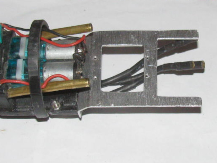
    Oh. . . I will not be mounting the front rear tray to the back rear tray.
    While fitting the motor tray in an out trying to align it, I noticed the air pump tray will bounce up and down with the motor rotation because of the1/64"-minus offset.
    But while turning the cylinder over and over checking clearances, I see that I can make 2 aluminum strips to go from the tray under and around the motor to the air pump tray.
    The motor will not effect the air pump tray and the 2 trays will be solid to the end cap. (they can move independent of each other)

    So I made 2 strips to mess with and see if this works out.

    Weather says tomorrow and next 4 days the high will be in the 90s so I should be able to get more time in the shop.


    Drilled holes in corners of the openings.
    Last edited by Ralph --- SSBN 598; 06-21-2021, 11:02 AM.

    Comment

    • Ralph --- SSBN 598
      Junior Member
      • Oct 2012
      • 1417

      #32
      June 21th ======================

      My job today is to find tools to replace the ones I use and have broken

      First I did some searching on net.
      Found the mill bit.
      I should have know so looking would have been easier, it was not a mill bit.
      It was an air grinder burr bit.

      Any way. I found a set of 5 that has the size I use and 1 smaller and 3 bigger.
      Price as okay compared to others I looked at.
      Not expensive but not cheap either.
      Ordered it and it will get here in about 2 weeks.

      Now to find Dremel grinding wheels.
      I only have about 4 places with in 30 miles that might carry them.
      Check Lowes and found that 1 of their 2 stores has 3 packages.
      The other, none.
      For back up there is a little tool store that has some but at a high price.
      So, I think I need to get in the car and go.
      I can not continue on my Gato work with out the grinding wheels.
      The mill bit I can do with out using small files.
      Just much slower.

      I hope is to find the grinding wheels and get back in the shop tomorrow morning.
      Weather tomorrow says low 90s. That is great.Weather for Tuesday says mid to low 80's.
      I might have to get my coat out again.

      Beings I have to go to big town (34 miles) I will get other stuff not related to subs while there.

      Comment

      • Ralph --- SSBN 598
        Junior Member
        • Oct 2012
        • 1417

        #33
        Finally home from today's trip to town.

        I have in hand small plastic tube sort of with 12 metal grinding disks for my Dremel.
        This means I can continue working on the electronics tray.

        I found some 20 gauge wire to replace the bigger wires through the ballast tank.
        I will run test with the motor to check current draw.

        The mill bit I want to replace is not a mill bit at all.
        It is an air grinder deburring bit.
        Got those on order and will be here in a week.
        I continue working without it. (files)

        Tomorrow I have no place to go and can start early in the shop.
        I hope to get the tray finished and mounted on the end cap.
        ===================
        Forgot to mention, I was at the post office and the magnets for the control linkage are here.
        They are strong little buggers.
        3/16"x1/4" at N48 strength.

        There are 50 of these little magnets.
        I opened the package and messed with them.
        I found I could put them all in line, one after the other and then pick up the complete line of magnets from just hold there end magnets.
        Not hanging down but holding then horizontal to the desk.
        Last edited by Ralph --- SSBN 598; 06-21-2021, 05:47 PM.

        Comment

        • Ralph --- SSBN 598
          Junior Member
          • Oct 2012
          • 1417

          #34
          June 22nd ======================

          Out in to the shop early.
          I finally got the motor to turn freely.
          I cut the tray removing the servos from the tray leaving only the motor on the bracket mounted to the end cap.
          The servos were heavy enough to apply down pressure on the end of the tray binding the motor in the bushings.
          Once the motor turned freely, I installed the gear box.
          Gain the motor start binding.
          Measuring and using a square, I found the gear box was lifting the shaft up as it came through the end cap.

          The end cap has a brass tube bushing. The gear box has 2 brass bushings. (one on each side of the gear box frame)
          The end cap and inside gear box bushings where so close they touched.
          I knocked the inside gear box bushing out of the frame and no the shaft uses the end cap bushing and the outside gear box bushing.
          Motor now turns freely again. (there is plenty of support for the shaft.

          On to the air pump tray.
          I have to figure out how and then build a tray to add to the air pump tray to hold the 2 servos.
          Currently building up the plastic section under and behind the air pumps.
          Once built and cured, I can start making the frame to hold the 2 servos.
          I have checked for clearance and it is there with room to spare.

          Just a lot of small parts in plastic and aluminum to make and assemble to get every thing to line up.

          I gained another 1/4" in the compartment by cutting the servos from the motor tray.

          All these small parts make it a slow build.

          I looked at the magnets I received and I have all the brass tubing sizes to make connectors.
          What I found to be short of was 1/8" wheel collars. I have plenty of 1/16" collars.
          Order 1/8" collars and will be here next week.

          Things are going slow but progress is being made.
          -----------------------------
          The plastic parts will not work where I want then.
          So, I made aluminum parts.

          The aluminum tray section that holds the 2 servos and connects to the air pump section is now cut out and drilled for screws and bolts.
          I need to make 2 strips about 3/16" wide and about 3.5" long.
          I need to bend one end of each 90 degrees to mount to the end cap next to the motor bracket.
          Once I have those made and bolted to the end cap, I can slip the air pump and motor trays in to my test cylinder to see how long the 2 strips need to be to hold the air pump tray clean of the motor.
          Knowing the length I can drill and bolt the strips to the air pump tray.
          This will keep every thing clear of the motor tray and motor.

          If the aluminum strips do not do the job, I think I can use brass tubing with flatten ends.

          I am done for the day.
          I forgot to take my morning meds and I just ran out of energy.
          I will go fix this issue with lunch.
          Last edited by Ralph --- SSBN 598; 06-22-2021, 04:11 PM.

          Comment

          • Ralph --- SSBN 598
            Junior Member
            • Oct 2012
            • 1417

            #35
            June 23rd ======================

            I think I have finished making aluminum brackets.
            I need 4 very small bolts which I will get today.

            Now for some photos. (FINALLY)

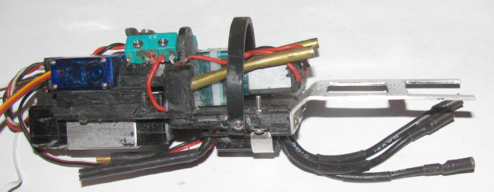
            Here is the servos bracket mounted to the air pump tray.


            Side view.


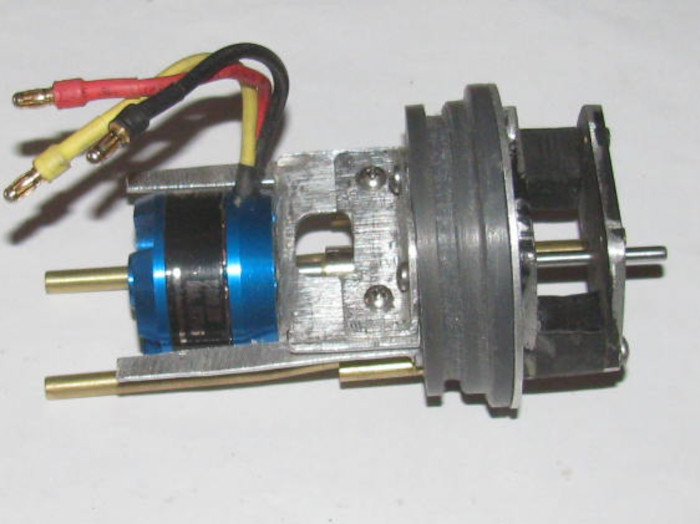
            Motor tray with the bracket extensions mounted to end cap.
            The extensions do not touch the motor tray.
            One on each side about 1/4" wide strips of aluminum.
            Look at bottom of tray.


            Here both the air pump tray and the motor tray on end cap slid in to my short test cylinder.


            Side view.
            4 small bolts, 2 on each side will hold the extensions to the servo tray.
            This will make all the trays in to one units so the servo control rods can not push them apart.
            I will need to shorten the air intake/outlet brass tubes.
            I also will need to do a little bend of these tubes so they line up again.


            It all fits and is about 2" plus shorter.

            Comment

            • Ralph --- SSBN 598
              Junior Member
              • Oct 2012
              • 1417

              #36
              Back with the 4 bolts.

              Took the trays out to the tool shed.
              Tool shed has the drill press.

              Now to drill holes in the 2 tray parts.
              Measured the motor frame with the air pump frame and marked where I needed 4 holes.
              I only drilled holes in the motor tray.

              I will then drill 1 hole in the air pump tray with the motor tray clamped to it.
              Once I get 1 hole drilled, I will put a bolt through and tighten it up when I get the 2 frames straight. (by testing in cylinder)
              Drill another hole and put in another bolt
              Continue until all four bolts are in.


              All the rear compartment trays and brackets are assembled.
              Next will be installing 2 servos and running wires.
              Last edited by Ralph --- SSBN 598; 06-23-2021, 04:33 PM.

              Comment

              • Ralph --- SSBN 598
                Junior Member
                • Oct 2012
                • 1417

                #37
                June 23rd ======================

                Today, I have bent the air inlet/outlet brass tubes so they line up for the rubber hose.
                I did not have to cut the brass tubes.
                There was enough room to slip the rubber hoses on.
                This also gave me more clearance from the motor.

                On to the 2 servos.
                The holes I driller were off a little.
                But to make them work I files the screw holes on the servo tabs a little wider.
                Worked out great.

                Mounted the rudder and rear planes servo.
                Time to test fit the control rods.
                Fit like I measured it all.
                I sort of used the old cap to guide me.
                Small changes here and there.
                Looks like I will need to bend the 1/16" rod at the servo ends about 1/16".
                There is 1" 1/16" rod from the clevis to the 1/8" brass tube that goes through the end cap and seal.
                That will wait until I power up the systems to see how the control rods move.

                With the shortening of the trays, I needed to make the 1/16" control rods that are on the servo end, shorter.
                I measured what I needed which was 1" on both control rods.
                Got out the soldering iron and small vise and removed the clevis ends from the control rods.
                Ended up cutting about 1.25" off each rod.
                Soldered the ends back in to the larger tubes making sure I have 1" between the clevis and the larger tube.

                Next I test fit the long 1/8" brass tube that activates the 2 air pumps and the ballast tank vent valve.
                In the photo above, tube goes through the center end cap tube.
                Between the 2 larger air tubes.
                It goes back through a plastic guide just to the right of the green switches.
                The long tube goes between the 2 switch with wheel collars on the tube to activate the switches.
                The test fit shows it will work but the control tube is so close to the motor housing I decided to move the bushing tube in the end cap.
                I have a brass 1/8" rod with a ring of brass tube slipped over and soldered just for removing through cap bushings.
                Couple of taps with a small hammer while the end cap is supported with crack the glue and the tube comes out with a little effort.

                Cleaned the glue off the bushing tube and then I cleaned out the hole through the end cap.
                With a small file I enlarged the hole in the end cap .
                I move it up and away from the motor.
                Testing several times as I go.
                Got to be careful not to file in to the o-ring groove.
                Files until I got about 1/32" clearance from the motor.
                Checked the material on the end cap to the tube.
                Plenty.
                Looks like about 1/8" or more from the bottom of the o-ring groove.

                I put the control tubing through the end cap and through the guide by the switches.
                I put the short brass tube bushing on the control tube.
                I silicone grease the control tube so if an glue gets on it, the tube will slip out.
                Put glue on the bushing tube and pushed it through the end cap to the proper depth.

                I put a small wedge of soft foam between the motor and the control rod.
                Making sure the control rod does not settle down on to the motor housing.

                Now to let the glue cure.
                Once the bushing is cured in place, I will use a short control rod piece and put it through the bushing.
                Tape it on the inside of the end cap.
                Set it up in the vise and file the o-ring recess.
                Then I can fill the recess with glue and when cure recut the recess.

                Now a thought.
                I should test fit the o-ring seal before filling the recess.
                I may not have taken enough material out of the end cap to make this step necessary.
                Yep, test fit o-ring first.

                Comment

                • Ralph --- SSBN 598
                  Junior Member
                  • Oct 2012
                  • 1417

                  #38
                  June 25th ======================

                  The control rod for the air pump switches and ballast tank vent has been cleaned up and works great.
                  Plenty of clearance from the motor.

                  I installed the rudder, rear planes and air pump control rods.
                  Connected servo horns.

                  Charge the 2 boat batteries.
                  Now to connect the power and start connecting the servo plugs.

                  One by one I plugged in servos and tested.
                  As I go they are working as they are suppose to.

                  I have 1 bad servo on the bow plane retract.
                  Sounds like the gears have a lost tooth or two.
                  Not a problem, I have plenty of these little servos.
                  I will replace it.

                  Now the fun begins.

                  Powering up the main motor.
                  ECS beeps when turned on but it did that when powering up the servos.

                  Okay, operate the Tx control stick.
                  Motor stutters in both directions.
                  Tried this several times with the same effect.
                  Then the motor stopped all together.

                  Removed the motor from the electronics tray.
                  Dis assembled the motor.
                  A single spring "C" clip and then tap the shaft with wood block.
                  I have the motor a part on the bench.
                  Well I see the problem immediately .
                  The several months I have been rebuilding the electronics trays, I have had to move the motor wires and all other wire so many times to work around them, that the 2 wires to motor have separated or broken.

                  This is something I can not see me fixing.
                  Not a motor guy.

                  I am seeking help to repair and I have also sent a message to Engels about replacements. (their web pages say OUT OF STOCK)
                  So the Gaot project is now stopped until I can find out what I can do.

                  I might be able to reassemble the motor and reinstall it to do water trimming.
                  Everything works except the main motor. (just not plug it in to power)

                  The Engel's motors are low RPM and high torque.
                  I looked for weeks for a similar motor for the rescue barge.
                  NO luck at all finding a match.

                  The Engels motors run so smooth without cogging at low speed.

                  If I can get another Engels motor, I may have to order several just for shop stock here.

                  So today was a good day except for the motor issue.

                  Comment

                  • Ralph --- SSBN 598
                    Junior Member
                    • Oct 2012
                    • 1417

                    #39
                    June 27th ======================

                    Yesterday, I looked at the motor armature (where the wires connect) with a 10X magnifying loop.
                    After a few minutes the conclusion is the motor is junk.

                    So I am looking for a new motor and Engel's does not have the correct motor in stock.
                    Been a couple of months out of stock.

                    But they have a large motor. (500)
                    I did some research and learned what all this stuff about brushless motors means.
                    Okay, the motor I wanted is a 300kv motor.
                    I have it in 2 subs and like it a lot.

                    When comparing the 500kv motor it was a first a problem.

                    The kv number multiplied by the battery voltage gives maximum rpm.
                    Out comes the spread sheet.
                    Reason for that is the Gato is 7.4v and the other 2 subs are 12v.
                    Turns out if I use the 500kv motor the rpm comes down to only a 100+ rpms difference.
                    The Tx I am using to runt he Gato is a Futaba with computer adjustable channels.
                    If I adjust the Tx to 50% then the 500kv motor will run slower than the 300kv motor in my other boats because of the battery voltage difference.

                    So the Gato is back on track.

                    I will order motor Friday because Engel's is closed for a week.

                    Now in the shop, I am measuring the cylinder and the electronics trays to see where the ballast tank frames will go.
                    Starting at the back, I slid the tray and equipment in to the cylinder.
                    Marked the cylinder for the ballast tank frame.

                    With this mark I can fine where to put the vent valve body on top of the cylinder.
                    3/4" in front of the frame. (used old cylinder to see where I put everything on it.

                    Drilled the vent hole in the cylinder.
                    Place the vent valve body over the hole.
                    The vent body has a short piece of brass tubing sticking out that goes in the vent hole in the cylinder.
                    Keeps the valve body from moving when the control rod and springs are attached.
                    Drill the 2 bolt holes to hold the valve body on.

                    Moved on to make the 3 plastic control rod guides that will mount on the top of the cylinder.
                    Currently in the vise and will be shaped later.

                    Well it is hot in the shop but still tolerable.
                    So, I started cutting brass tubing pieces in various sizes. (diameters)
                    The little magnets showed up Friday.
                    I am going to slip the magnet in to the large brass tube and then size it down to the control rod size.
                    I have 2 sets at different point of completion.

                    I am going to wait and see how these work l before doing the bow plane connectors.
                    These little magnets feel like they might be too strong. (I might have to go 1 size smaller in diameter 1/8")

                    Okay, now it is hot in the shop.
                    I give up.

                    Comment

                    • Ralph --- SSBN 598
                      Junior Member
                      • Oct 2012
                      • 1417

                      #40
                      June 28th ======================

                      Saturday, I got an e-mail saying the wheel collars I ordered last week where delivered to the post office.
                      Went to town and picked them up.
                      Did a couple of other things while in town.

                      Out to the shop.
                      10 am and it is already hot.

                      No matter, I will see what I can get done.

                      Got the 3 plastic pieces out of the vise.
                      Set them aside with the other parts.
                      Not going to work on them in the heat.

                      So I will continue making the magnetic connectors.
                      Cut lots of brass tubing in various lengths.
                      On to assembling them.
                      Get 4 magnets out of the baggie.
                      I made the parts that hold the magnets the other day, so now I am slipping tubes to go from 3/16" ID tube to 1/16" id tubing.
                      The part that holds the magnets is made of 2 brass tubes slipped together to give me a shoulder to push the magnet against.

                      I have cut enough parts.
                      Put glue on magnets, one at a time and slip in to connector.
                      Next I put glue on the 2 tubes that slip in to the connector.
                      Did this to 2 magnets.
                      Put the unit in the vise.

                      Now I take magnet and place it on one of the magnets in the connector.
                      It will self align by flipping around to mate up.
                      Glue in connector and on tubes.
                      Slip together.
                      Do the 4th one.

                      I now have 2 magnetic connectors for the control rods.
                      I will let cure over night and then clean them up.

                      Okay, it's now 12:30pm and I am hot. (112 F in the shop)
                      The tools are hot to the touch.
                      Time to go inside the house.

                      Making the magnetic connectors was easy enough.
                      I think I will make connectors for the bow planes.

                      Not today.

                      Comment

                      • Ralph --- SSBN 598
                        Junior Member
                        • Oct 2012
                        • 1417

                        #41
                        Sitting here staying cool, I think when I make the bow planes magnetic connectors, I will get photos of all the steps.
                        I am here thinking I have run out of the small diameter brass tubing that slips over the 1/16" rod.
                        Looks like a trip to town in the next day or 2.
                        Maybe not. I have appointments at the VA this week.
                        Just looked t make sure.
                        1 year follow up on the lens replacement in my right eye.
                        My opinion is both eye surgeries turned out amazing.
                        Second eye follow up is in Sept.

                        Comment

                        • Ralph --- SSBN 598
                          Junior Member
                          • Oct 2012
                          • 1417

                          #42
                          June 29th ======================

                          Good news from Engel's.
                          The 300kv motors are in stock.
                          I ordered 3 this morning.

                          Out to the shop to work on magnetic connectors.
                          I made the 2 sets for the rudder and rear planes.
                          Forgot photos.
                          So I started making 2 sets for the bow planes.
                          I cut all the brass tubing pieces.
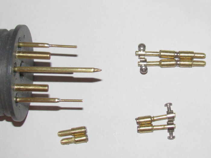
                          I tried to show them all but the magnets would not let me put them all in the same photo.
                          The magnetic attract from 5" away.

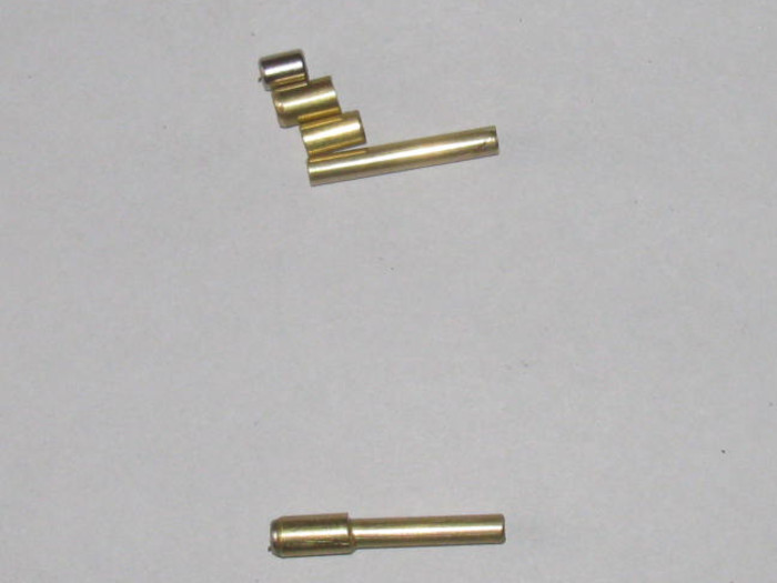
                          So here are the parts for 1 magnetic connector.
                          Top part is the magnet.
                          Going down are tubes reducing in size to slip together.
                          At bottom of photo is a completed connector.
                          It will slip over the control rod end which is 1/16" brass rod.
                          A wheel collar will hold it in place.
                          There will be 4 with the wheel collar which go on the control rods coming through the end cap.
                          The control rods going to the planes and bow stuff will be fixed on the control rods.

                          There is 1 more brass tube. I do not have the one that slips over the 1/16" rod.


                          Size. The small tube on the right is 1/8"OD.

                          I will get these assembled today except for the smaller tube.

                          I also built the three vent control rod guides that mount on top of the cylinder.
                          Still need to measure and drill the holes for the rod before installing on the cylinder.
                          Last edited by Ralph --- SSBN 598; 06-29-2021, 03:29 PM.

                          Comment

                          • Ralph --- SSBN 598
                            Junior Member
                            • Oct 2012
                            • 1417

                            #43
                            June 30th ======================

                            Today was a VA appointment.
                            Followup to eye surgery a year ago.
                            All good.

                            Got home about 10:45 am.
                            Decided to go out to the shop and see what I could get done in the 106F heat.

                            I assembled the 4 magnetic connectors for the bow planes.
                            Just a matter of applying glue and slipping together.
                            Making sure I have the magnet ends correct.

                            Okay.
                            I have 3 plastic parts that will guide the vent control rod that I assembled the other day.
                            I shaped them and fitted the base to the cylinder diameter.

                            Got to wait for the glue to cure.
                            17 hours minimum.

                            Good time to stop and go inside the house where I have the cooler running.

                            Tomorrow I may not get any thing done.
                            Tomorrow I think I will run around town for brass tubing and other parts like bolts to replace the grub screws in the wheel collars.

                            Something I do because the little Allen set screws tend to strip out where the Allen wrench does not work, I replace those with stainless bolts with Phillip's heads.
                            These work on wheel collars I use on control rods and do not need to be balance for spinning.
                            With the Phillips head bolts, I can get them tighter and still loose them when needed.

                            Comment

                            • Ralph --- SSBN 598
                              Junior Member
                              • Oct 2012
                              • 1417

                              #44
                              July 2nd ======================

                              Nothing was done yesterday.
                              I did get some parts while out and about.

                              So far this morning, I have finished cutting the brass tubing to make 16 reducers for the magnetic connectors.
                              Went from 3/16" id diameter of the magnets down to 1/16" id of the control rods.

                              4 connector pairs have been assembled and the glue is curing.

                              Now I am off to do real life stuff. (sure does get in the way)
                              -----------------------------
                              Back for town and took the bolts out to the shop.
                              These bolts are for the wheel collars.

                              I even put a bolt in to a few of these as I need 4 now.
                              Took a wheel collar with the bolt and slipped it on to the magnetic connector shaft.
                              Wait, did I screw the bolt in to far?
                              Nope!

                              Okay, what did I do wrong.

                              A quick inspection and it was easy to spot.
                              I had added 1 too many long brass tubes while reducing the size from the 3/16" to the 1/16".
                              The wheel collar would not slip over the outside tube.
                              Second or third one in the reducing sequence.

                              Easy enough to fix.
                              The glue I am using takes 17 hours to cure.
                              So I took 2 pairs of pliers and twisted the tubes and they cam out.
                              I cleaned up the inside of the tube with a drill bit.
                              Cut the over sized tube down to be flush in the connector and leave the correct tubes sticking out.
                              Cleaned up those tubes and applied glue and slipped together.

                              I did check the wheel collar fit before the gluing.

                              So by morning, the connectors should be ready to cleanup and fit to the control rods sticking out ot eh end caps.
                              The I can measure in the control rods in the boat.
                              Rudder, rear planes, bow plane retract and bow plane pitch.

                              With the wheel collars I should end up with 3/8" of adjustment on each connector.

                              Not so hot in the shop.
                              Only about 100 F.
                              Should not get hot until next Wednesday or Thursday.

                              Next Wednesday I plan to prepare my Akula II and my barge for Saturday's gathering at the lake.
                              Just need to check the batteries.
                              Last edited by Ralph --- SSBN 598; 07-02-2021, 07:08 PM.

                              Comment

                              • Ralph --- SSBN 598
                                Junior Member
                                • Oct 2012
                                • 1417

                                #45
                                July 3rd ======================

                                In the shop about noon.
                                Warm but not to bad.
                                I have to trim glue before it turns in to rock and I can not cut with knife and have to use a grinder.

                                I finished 4 sets of magnetic connectors.
                                Rudder, rear planes, bow retracts and bow pitch.

                                As I assembled them I made sure the magnets where installed so they were opposites.
                                Take the top pair. (rudder and rear planes)
                                They will not connect any way but like they are.
                                If I try to switch the top to bottom they will repel.
                                So as I put the cylinder in the hull, they should connect on their own to the correct partner.


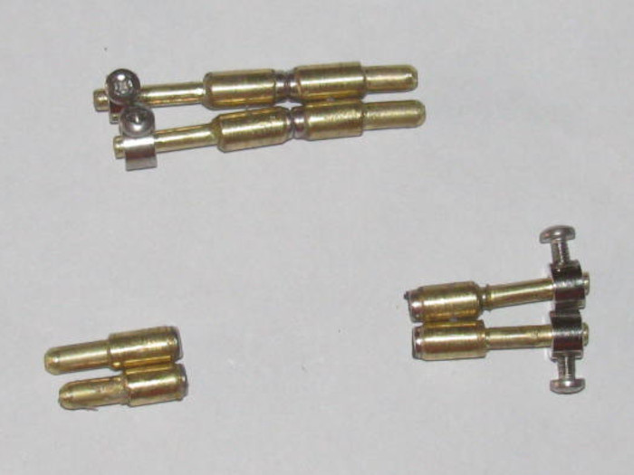
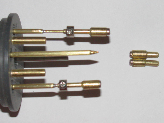
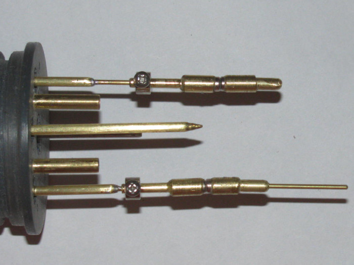
                                I put the rear end cap in the photo.
                                I have cut the control rods coming through the end cap to length.
                                The 1/16" control rod will slip in to the connector all the way to the magnet base.


                                Here the adjustable connector is slipped on to the control rod.
                                The top one is all the way out to full length.
                                The bottom one is all the way in .
                                The amount of adjustment can be seem by how much control rod is showing in at the top connector.
                                About 3/8" plus.


                                Put the non adjustable connector on to the end cap connectors.
                                The bottom one has a length of 1/16" brass rod in it.

                                You can also see the small bolts I use instead of the Allen screws.
                                These are so much easier to tighten and loosen that the Allen screws that strip out too easily.
                                The bolt goes through the tubes on to the rod.
                                No soldering required. Just a drill.


                                Once I get the cylinder completed, I can put it in the hull and then cut the control rods in the boat to length.

                                Comment

                                Working...
                                X