Gato build has resumed.

Collapse
X
 
  • Filter
  • Time
  • Show
Clear All
new posts
  • Ralph --- SSBN 598
    Junior Member
    • Oct 2012
    • 1417

    Gato build has resumed.

    Last year I was building a Gato.
    It was complete but during water testing, I could not get the boat to waterline without giving up full dive.
    So, I took it apart and made the ballast tank bigger.
    I was in the process of reassembling the cylinder when a problem came up.

    I was running my Akula II at the lake and ran the batteries down until the speed control BEC cut the main motor circuit.
    2 hours waiting for the wind to come up to push the sub to the beach.
    While sitting there because I did not take a second boat, I decided to build a rescue boat that will always go to the lake.

    That weekend, I moved the Gato off the work bench and started the rescue boat.
    That build is in the Surface Boat section.

    Saturday, I put the Gato back on the work bench.
    Took an half hour to find all the parts that go on the cylinder.
    Yesterday, I opened the cylinder and found several wires not plugged in.
    Guess they were loose so I could put the electronics tray in and out of the boat while rebuilding the ballast tank.

    I was going to work on the assembly of the cylinder today but that changed.

    Lately the weather here has been very dry.
    And every thing I touch shocks me with static.
    This morning when I turned on the speakers to my computer, I got zapped again from the speaker switch.
    This was a big one.
    The speakers work but the LED light no longer comes on.
    The spark killed it.

    So, erring on the side of safety, I am not going to touch any boat parts until the humidity comes up a little.
    I do not want to kill and electronics.
    I also, plan to dig out my grounding wrist strap.

    I have all that in place as I reloaded ammunition commercially in this shop for 20 years.
    -------------------
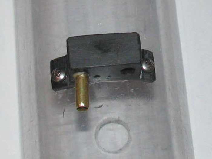
    While in the shop yesterday disassembling the cylinder, I looks like I stopped during final assembly.
    It should not take long to get it together and start water testing again.
  • Ben Brigham
    Junior Member
    • Sep 2019
    • 75

    #2
    Great news, Ralph! If you get a chance, please post some pictures of the Gato.

    Comment

    • Ralph --- SSBN 598
      Junior Member
      • Oct 2012
      • 1417

      #3
      May 25th ===========================

      Finally back in the shop after the barge build.

      I am going through the electronics trays.Making sure all connections are correct.
      I have put the rear electronics tray in to the cylinder.
      Pulled the wires through the ballast tank and I connected the plugs to the front electronics tray.

      Every thing was tested and every thing works.

      I have the front tray out of the boat to charge the batteries.
      The Tx is also on the charger.
      I thought I got LiFe batteries for the Tx.
      I will have to look.

      I have run in to a problem.
      The tape that holds the 2 battery packs in the tray has pulled the battery labels off.
      I do not remember the numbers on these batteries.

      How can I figure out what they are?

      If I can get the batteries charge in the boat, I should be water testing tomorrow.
      ----------------------
      I decided to take the batteries out of the tray and remove the tape holding them together.
      Surprise.

      I had placed the batteries for the battery information of both batteries were facing each other.
      I only lost the scanner code bars.

      So, I have the battery info needed to setup charger.
      ----------------------
      Once I setup the charge correctly, I now have 2 charged batteries for the Gato.

      Looked around and found a LiFe Tx battery on the work bench under a lot of parts and tools.
      Put it on the charge only to see the battery was fully charged.
      I know this battery has to have been on the bench for 4 months or more. (that's when I bought these LiFe batteries)

      Tomorrow, I will wrap the 2 batteries and install on the front electronics tray.
      Hookup the 6 plugs and test the system.

      If it works correctly, the front electronics tray will be slide in to the cylinder.
      The tray is mounted on the front end cap.

      This will seal the cylinder and I can put the cylinder in the water to test for leaks.
      If good, then in to the hull and connect all the controls for trim testing.

      When I stopped working on the Gato to build the Rescue Barge, I remember I was close to trimming again with the new larger ballast tank.
      The boat had been trimmed but I did not like the waterline and submerged trim.
      Not enough volume, so I added 1" to the ballast tank.

      I hope to have too much tank volume.
      I want to get full surfaced waterline.
      And when submerged the boat should sink.
      The ballast system is a snorkel system.
      I need the one mast that is the air tube to be above the surface.

      My plan is to put enough foam in the conning tower to stop the boat from going negative and have about 1/2" of the conning tower above the surface.
      I can change this foam block after I get a good waterline and the front planes should drive the boat to periscope depth.
      I do not need more than that.

      I also want the boat to come up to this 1/2" of the conning tower above the surface when I stop the main motor.

      I chose this system because I was using parts I had in the parts box.
      And there just isn't much room in a 2.5" cylinder for much after the ballast tank size needed.
      6 servos, ESC, motor, pitch controller, batteries and other stuff like wires and plugs.
      Last edited by Ralph --- SSBN 598; 05-25-2021, 06:11 PM.

      Comment

      • Ralph --- SSBN 598
        Junior Member
        • Oct 2012
        • 1417

        #4
        Ben, I had been posting my builds on SubPirates.
        Now that SP is gone, the build can still be seen on my personal web pages.
        I actually post to my web site then copy to the forums.
        You can see the entire build at http://www.cliffhangershideout.com/Gato/Gato-log-1.html
        Last edited by Ralph --- SSBN 598; 05-25-2021, 05:08 PM.

        Comment

        • Ralph --- SSBN 598
          Junior Member
          • Oct 2012
          • 1417

          #5
          May 26th ===========================

          Like always, other stuff got in the way.

          But I got about 30 to 45 minutes in the shop.
          I installed the charged batteries.
          I connected all the wire plugs.
          Got the Tx out and tested all controls.
          All looked and operated correctly.

          Folded the wires and slowly slide the front end cap in to the cylinder.
          I cleaned and grease the cap o-ring before finally sliding the cap in to the cylinder.

          Made up the 2 safety cables that go from the rear end cap to the front end cap to hold them on.
          They can not slide out far enough to break the cap o-ring seals.

          Other things are still happening so there will be no water testing today.
          But the cylinder is ready.

          Comment

          • Ralph --- SSBN 598
            Junior Member
            • Oct 2012
            • 1417

            #6
            May 27th ===========================

            Water test tank was filled.
            The cylinder was assembled completely.
            I almost forgot the rudder and rear planes boot seals.

            I have a fuel hose with a fitting to put on the front end cap which has a Schreader valve in it. (no internals in valve)
            Once the cylinder is in the water completely submerged, I can blow lightly in to the fuel hose creating a positive pressure in the cylinder.
            If there are any leaks, I will see bubbles.

            Okay here goes. . . . I see bubbles coming from the rudder boot at the exit end.
            I also see bubbles coming from the air to pump inlet and outlets. (not much)
            If I lighten the pressure these bubbles stop.

            So I will work on the rudder boot leak.
            I removed the boot on the control rod.
            I see what might be causing the leak.
            On the bottom of the control rod there is a small amount of soldier.
            I must not have files it down to the brass.
            With a fine small file, I removed the soldier and sanded with 200 grit paper.
            Reinstalled the boot and back tot he water tank.

            No bubbles from the rubber control boot.
            Still there are the bubbles from the air pump inlet and outlet.
            Lower the pressure and they stop.

            Now considering there is not pressure in the cylinder when operating.
            With the cylinder in the water and no pressure being applied, there are no water leaks in to the cylinder from the air lines.

            Next I need to put the cylinder in the hull and hook up all the controls
            Put the boat int he water and run the systems to see if they all work in the water and watch for leaks in the air system.

            What I can do is put a little pressure in the cylinder as I close it up.
            With positive pressure in the cylinder, it should keep water out.

            If the water does get in through the air system, it means removal and rebuild of the air system. (yuck)

            Right now the cylinder is drying.
            I am breaking for lunch.
            After lunch I will put the cylinder in the boat and ready it for the water tank.

            Comment

            • Ralph --- SSBN 598
              Junior Member
              • Oct 2012
              • 1417

              #7
              I put the cylinder in the hull.
              Hooked up the air hoses.
              Checked all controls.

              Out to the water tank.
              In to the water and this is when things started going wrong.

              First the motor would not turn the propellers.
              Lifted the deck off to see inside.
              The propeller shafts seem to be binding.
              The angle from gear box to propeller shafts is to great.

              Continue on with testing.
              Dive planes retract/extend failed to come up.
              Down okay but up I could hear the servo gears jumping or stripping.
              (Know problem with these servos. I have lots of them)
              Air pump is not adjusted correctly.
              Only 1 pump comes on and when the control is moved for both to run, it did not happen.
              This is an adjustment on the control bar in the cylinder.

              All but one items is a matter of adjustment and replacing the bad servo.

              The propeller shafts will require modifying the gear box and main motor location.
              This may require the building of a new rear electronics tray to move the motor.

              I will disassemble the cylinder and get the rear electronics tray out of the cylinder.
              I am wondering if I were to move the motor down and turn the gear box 180 degree, would the propeller shafts be more straight?

              One more thing.
              The ballast tank 1" extension did not give me the waterline I wanted.
              But that may be just a trimming issue.
              The extension went forward and I may need to move weight forward to compensate for the extra buoyancy to lift the stern.

              I will go after these issues one at a time.

              The propeller alignment will be fist and require the most modification.

              One thing I learned that no one could tell me, was, can these little air pumps pump water as well as air.
              First time int he water tank, I had the air inlet and outlet reversed.
              I recieved an unexpected shower from the 4 small holes in the mast that is my air intake.

              I was wonder because if I were to run the boat and the inlet go under could the pumps pump the water through and then followed by air.
              The answer is yes, though I hope not to make this a normal running procedure.

              Last point.
              There is no water in the dry sections of the cylinder after an hour of testing.

              One safety cable needs to shortened a little.

              Comment

              • Ralph --- SSBN 598
                Junior Member
                • Oct 2012
                • 1417

                #8
                Since testing earlier today, I have been thinking about this boat.
                The hull went together rather quickly.
                But the stuffing of all the electronics and pumps and servos and ... and ... and is beating me down.
                Everything I try seems to work on the bench but as soon as it goes to the test tank, it either works poorly or not at all.

                I have been fixing things that don't work right for more than a year.
                Still I am no closer to being done than the day I started this build.
                I even took time away from it with the hopes of coming back with more energy for it.

                I am not giving up just yet.
                The boat would look good on a wall shelf.

                I have things to do tomorrow so I will not let the boat worry me.
                But come Saturday, I think the plan will be to remove everything from the cylinder and start over.
                The 2 servos in the front could use better alignment through the end cap.
                All the wiring could use better routing through the cylinder. (there's just too much to stuff in the forward compartment)
                The rear compartment will need to be completely disassembled.
                I need to get the propeller shafts and the gear box in a more straight line.
                This will require moving the main motor.
                The 2 air pumps need a better manifold or I need to come up with a different ballast system all together.

                So, I need to go at it as if I had not built any of it.

                Maybe a 3 piece cylinder so I can get a bigger section for the ballast tank which could be shorter giving me more room in the front and rear electronics sections.
                This might allow me to make a piston system. (I have space for the long threaded rod if the motor is mounted lower)

                I will make hard paper card mock ups before cutting and shaping aluminum trays.

                If I remove the off/on switch, I could get 3/4" more free space in the front compartment.

                I might try batteries in the wet and move them under the bow deck in front of the planes mechanism.
                That frees up 3" in the front compartment.

                Until I get started on the new build, I don't know how I will put it together.

                The quick fix would be to remove everything but the motor and rudder controls and make it a surface boat.

                Kidding......If it is not a submarine, it is a wall hanger.


                Sorry, frustration hit me this afternoon.

                I need photos of your working Gato cylinders.
                I need to see what works and how it is placed in the cylinder.

                I have read so many Gato builds, I just don't want to do that again.

                Comment

                • Ralph --- SSBN 598
                  Junior Member
                  • Oct 2012
                  • 1417

                  #9
                  May 28th ===========================

                  Got done earlier than expected today. (doing other stuff)

                  Out to the shop and disassembled the rear electronics tray.
                  I wanted to see if I could straighten the propeller shaft to gear box angle.

                  The answer is, Maybe.
                  I will need to move the motor through the end cap down about 3/8".
                  As the gear box is made, I can not move the motor and get the full 3/8" drop.
                  The motor would sit on the cylinder wall.

                  Now I measured everything and I think I can do this if I change the gear on the motor shaft.
                  It is 28 teeth gear.
                  I ordered a 12 and a 14 tooth pinon gear.
                  I hope this will give me the room needed.

                  I looked at the air pumps to see if I can change the the inlet and outlet locations.
                  Part of the air leak is that I have the air in to ballast tank at the top of the tank.
                  When the pumps are off, the water pressure in the ballast tank is pushing air back through the pumps.
                  If I have room I could probably use a check valve in that air line.

                  But if I move the hose so the end of the hose is at the bottom of the ballast tank, the pressure in the ballast tank will not push air out the air hose.
                  To do this, all I have to do is run a 1/8" brass tube from the end of the end cap where I can connect the air outlet in the end cap to this brass tube and the other end will end with a 90 degree piece so the air will bubble up through one of the ballast tank flood holes.
                  I made the holes a little too big and will be putting a piece of plastic over 2 or the three to make them smaller.

                  I need to pressure check the air pumps.
                  Put a fuel hose on the inlet and blow through it lightly and see it the air leaks out when I plug the outlet with my finger.

                  If this test shows no leak, I can use the original rear end cap instead of making a new one.
                  Just fill the original motor shaft bearing hole and drill a new one once I get the new pinon gear.

                  Looking at the electronics tray, I see I can move the 2 servos rear word and make the tray 1/2" shorter.

                  I do not remember building the rear electronics tray in 4 sections.
                  I can move each section up or down with shims as needed for height.
                  I guess when I was build the tray, I was planning ahead to access problems.

                  When I removed the rear tray, I have to remove the front tray to get to the wire plugs.
                  I can save room by changing the main power wires.
                  They are 18 gauge but they are also silicone insulated.
                  This makes for very thick wires.

                  I am going to get some 22 gauge stranded wire with standard insulation and see if this helps with folding the excess in the front compartment.

                  I reread my original build and trimming.
                  I may have over looked trimming process.

                  In the water the bow is high and the stern is low by 1/2".
                  I think I left out a movable ballast block that goes up near the bob.
                  Pushing the bow down will bring the stern up.

                  I found the ballast block on the bench.
                  It is marked bow block #1.
                  Seem like it should be in the hull.
                  I also had a slight roll to the side during surfacing.
                  This block would also help that problem.

                  I got a lot done in 1 hour in the shop.

                  Got to find another hobby shop.
                  The one I used for years closed and moved.
                  Don't know where it went yet.

                  Anyway, progress continues.

                  Comment

                  • Ralph --- SSBN 598
                    Junior Member
                    • Oct 2012
                    • 1417

                    #10
                    May 29th ===========================

                    In to the shop to get after the Gato issues.

                    With the rear electronics tray disassembled in to 3 sections, I can measure parts as needed to modify the trays.
                    I started with the motor and gear box.
                    The gear box will be turn 180 degrees to get the main motor lower in the cylinder but more importantly, I need the 2 out put shafts for the propellers to come up higher than they are.
                    The angle was just too much for the dog bones.

                    Well the measuring tells me I can not use the original end cap.
                    The 5 brass tubes coming through the end cap can not get past the gear box.

                    Beside, I have 2 small pinon gears coming which will help move the bear box down.
                    I did measure the motor and the cylinder clearance so I could drill the end cap for the motor bearing.
                    Using a short piece of cylinder, I can get in there with a pencil to mark the end cap and motor shaft position.

                    Drill the end cap for the shaft which leaves a little room to file the hole in any direction needed when I file the hole bigger for the bearing.
                    Turns out, I hit right where it needs to be.

                    I put the motor shaft extension through the end cap and slipped the gear box on the shaft.
                    Before I drill holes for the control rods and air tubes, I will wait for the smaller pinon gears.

                    Next, I worked on the second tray inline to move the servos.
                    What this did was remove a gap of 3/8" between the motor end and the air manifold.
                    This was a matter of cutting a little plastic off the tray allowing the servos to move closer to the manifold.
                    When I start assembling every thing, there will be a little more removed from the aluminum part of the tray when I know exactly where the motor ends up.

                    Third Item.
                    I woke up this morning with a thought on how to plumb the air from the read end cap to the ballast tank.
                    My air leak was because the pressure in the ballast tank full of water was push back through the pumps.
                    So, the though is to bring the air in from the bottom of the ballast tanks in one of the flood holes.
                    I will use brass tubing (5/32" id) running in the bottom of the hull on the keel center line and make a 90 degree turn up under the flood hole.
                    The back end of the tube will be turned up about 45 degrees so I can slip the rubber fuel hole on to it when the cylinder is in the hull.

                    The same with the intake.
                    Brass tube under the cylinder on the center line and turned up at the back of the cylinder and up at the front end so I can get a rubber fuel hose up in to the conning tower to connect to the mast snorkel.


                    More weight in the bottom of hull on center line.
                    No long rubber hoses getting tangles and never in the same place twice.

                    Now the bad news. )^;
                    I bumped the cylinder and it fell to the floor.
                    Concrete floor.
                    Looked over the ends and though I was lucking.
                    Then I noticed at 2 of the 3 flood holes, there are cracks.
                    In the ballast tank not a problem. (I have repair that)
                    But the back flood hole has cracks and they radiate out and under the ballast tank frame seal.
                    Looks like I will be ordering a new cylinder piece.

                    I managed to move on.

                    I have a box of rejected end caps of various diameters and thickness.
                    I found one that looked like it would work.

                    I put it in the drill press and turns a new end cap.
                    It was 1/2" thicker than needed so I cut it out while in the drill press.
                    There are two 1/8" and the 1/4" center hole for the turning bolt.

                    I taped over the 3 holes.
                    I put a drop of thin CA in each hole and will let cure.
                    After it cures, I will fill the holes with Gorilla glue. (I use this because it expands and seals the holes)

                    I removed all the brass through tubes from the original end cap.
                    They are Gorilla glued in.

                    This is very easy.
                    Place the end cap on an open vise jaw.
                    Hold my soldiering iron on the end of the through tube closes to the end cap plastic.
                    I can see the plastic start to smoke.
                    Put the iron down and pull the brass tube with a little twisting.
                    They slide right out.

                    Put each tube in the drill press and clean the glue and plastic of each one to bright smooth finish.
                    ------------------------
                    I think I will be near McMasters-Carr end of this next week.
                    Order Tuesday and pick up Thursday.

                    Comment

                    • Ralph --- SSBN 598
                      Junior Member
                      • Oct 2012
                      • 1417

                      #11
                      Continuing in the shop ----------------------

                      I finish filling the holes in the end cap with Gorilla glue.
                      It will be ready in the morning to trim off the excess glue that expands out of the hole.

                      While out in the shop, I looked at the parts sitting on the bench.
                      The vent valve as it is is no longer needed.
                      It has the vent valve o-ring and springs but it also has the inlet air from the pumps.
                      I only need the vent valve part.
                      I will make another plastic part but first I wanted to see if I could modify the original part.


                      Removed the part from the cylinder.
                      I drilled a new hole for the air vent at the center of the part.
                      Then with a cut off wheel in the Dremel, I removed the plastic with the brass tube as close as I could get to the tube.
                      I cut the other side off, cutting in to the existing hole.
                      The inside of the part is hollow.
                      With the two ends cut off, I can see inside the part and make sure the new hole does not go all the way through.
                      I files and sanded the part to make the open ends flat.
                      I glued small square plastic pieces on the ends, closing the part up again.
                      I trimmed the screw flats back a little.
                      The screws will be close to the valve block.

                      What I have now is a small block with 1 hole in it for the vent on a shaped saddle to mount on top of the cylinder.

                      I will get a photo after the vent block comes out of the vise where the plastic is squeezed to make a good bond.

                      Comment

                      • Ralph --- SSBN 598
                        Junior Member
                        • Oct 2012
                        • 1417

                        #12
                        May 30th ===========================

                        Worked on the end cap.
                        Sanded both sides flat removing the expanded glue.
                        It needs more filling of the drilled holes.
                        Applied more glue in to the holes.

                        I did some measuring from the propeller shafts to the top of the lower hull.
                        Then I transferred these numbers to the end cap to find the center of where I need the 2 gears to be.
                        I appears I better wait for the new pinon gears to arrive before continuing with the end cap.

                        Okay. I am not ready for summer.
                        It got to 100F in the shop in short order.

                        I did get photos of the modified ballast tank vent.
                        It no longer has the air inlet tube. (Air inlet is being moved to the bottom of the cylinder)


                        The short stub of brass tubing goes in to a hole driller in to the top of the cylinder in the ballast tank section.
                        This is to help hold the plastic in place when the spring loaded valve is pressing against the plastic body.

                        Comment

                        • Ralph --- SSBN 598
                          Junior Member
                          • Oct 2012
                          • 1417

                          #13
                          May 31th ===========================

                          I had a little time this morning before getting to other non sub stuff.

                          I measured center to center of the propeller shafts in the hull.
                          Then I put the cylinder with the end cap in it to get the center of the shaft where it will meet the cap.
                          If I get this right, my propeller shaft dog bone will be straight. (no angle except that where the propeller shaft goes through the hull)

                          I laid out the drive shaft gears on a piece of paper.
                          Then I took the third gear to see if it would fit above the 2 drive gears.
                          But I also checked to see if the third gear would fit under the drive gears.

                          If I can fit it under the drive gears, this will leave a little more than half the end cap for control rod through bearings.

                          I cut 4 pieces of aluminum from my speed limit sign.
                          Cleaned the reflective coating off with the disk sander.
                          Sanded both sides.
                          Cleaned with thinner.
                          I glued the 4 pieces of aluminum in pairs.
                          Used tape to keep the pairs from sticking to each other.
                          Clamped them in the small vise.

                          I will shape them after they cure over nite.
                          I should have the pinon gear in the next couple of days.
                          Then I can start assembling the new gear box.

                          My new end cap fits very well.
                          I may not need to use the safety cables, now.
                          The original cap was water tight but not very tight in the cylinder. (I worried that it might pop out)

                          Did a little more filling of holes in the end cap.
                          When done, I should have only 1 hole for the main motor shaft.
                          Remember, I made this cap out of a reject 5.25" diameter cap that had hole in it for control rods. (not in the right place)
                          Now I have 2.5" diameter cap.

                          Comment

                          • Ralph --- SSBN 598
                            Junior Member
                            • Oct 2012
                            • 1417

                            #14
                            June 1st ===========================

                            I made it out to the shop.
                            The weather in the desert has turned.
                            By 10 am my shop temperature says 95F.
                            I am going to have to start earlier.

                            Okay.

                            Pulled the 2 gear box side plates out of the vise.
                            Did a little trimming but the glue is still tacky so I will have to wait another day before shaping.

                            Made a brass exhaust tube.
                            It goes from just past the back of the cylinder to the first flood hole in the ballast tank.
                            I cut a notch 3/8" back from the end of the tube.
                            When I bend it I get a 90 degree turn.
                            Solded the joint and checked for air leaks.
                            Good to go.

                            I cut a notch in the cylinder location plastic pin in the bottom of the hull.
                            Well, I tried to cut a notch in that pin.
                            One side broke off.
                            So I got scrap plastic pieces from the floor.
                            Making a new pin with the notch for the brass tube in it.
                            This will hold the 90 degree bend up in to the ballast tank.
                            The other end will be made after I get the gear box finished.

                            Measured the cylinder for length and OD & ID.
                            Order new cylinder from Mac-Masters.
                            Pickup on Thursday morning. (I had other things to do which are near their building)

                            Mostly of what I can do are busy work parts.
                            They can wait.
                            I am done in the shop.
                            It's up another 5 degrees in the shop.

                            Oh, while measuring and fitting the air exhaust tube, I measured the end cap to the propeller shafts.
                            Withe gear box output shafts now straight withe propeller shafts, I can make the cylinder another 1" or so longer.

                            Moving the equipment on the tray and an addition 1" of cylinder, I have gained about 1.75" inside the cylinder.

                            I maybe winning the equipment in the cylinder space race. (yea)

                            Comment

                            • Ralph --- SSBN 598
                              Junior Member
                              • Oct 2012
                              • 1417

                              #15
                              June 2nd ===========================

                              What did I get done today?

                              I shaped the plastic part that will be in the bottom of the hull to locate the cylinder.
                              It sticks up and will go in to the back flood hole of the ballast tank.
                              It has a slot in it to accept the air outlet brass tube. (air from the air pumps)

                              The location is about 1/4" forward of where it was originally.
                              It was right against the tank bulkhead and I wanted a little space between the two.
                              I used 1 hour epoxy to glue the part in place.
                              The brass tube is sitting in the slot to keep the part centered and the slot in the correct direction.

                              Checked on my 2 aluminum plates for the gear box.
                              A little cleanup and I was ready to drill the 2 output shaft holes.
                              I marked one of the plates and set it int the hull to make sure the marks lined up with the 2 propeller shaft dog bone connectors.
                              A little adjustment and out to the tool shed to drill the 1/8" holes.
                              Drilled 2 holes in the marked plate.
                              Held the second plate against the first and drill 1 hole on the second plate.
                              I put a 1/8" rod shaft in the 2 plates to hold the plates while drilling second hole in second plate.

                              This is all I can do until I get the pinon gears.
                              -------------
                              I got e-mail confirmation that the cylinder is ready for pickup tomorrow.

                              Comment

                              Working...
                              X