Gato build has resumed.

Collapse
X
 
  • Filter
  • Time
  • Show
Clear All
new posts
  • Ralph --- SSBN 598
    Junior Member
    • Oct 2012
    • 1417

    #46
    July 4th ======================

    I had about 20 minutes out in the shop before other stuff happens.

    So I measured the 2 dog bone extensions.


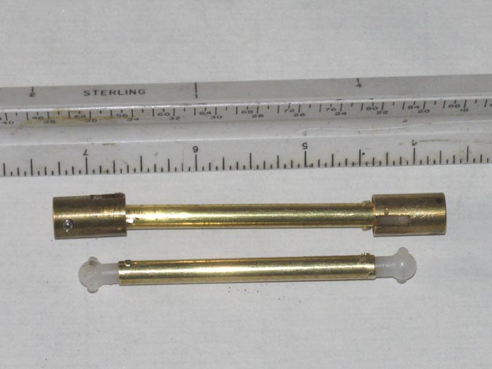
    I need to shorten the dog bone by 7/8".
    Grind off the heads of the brass pins.
    With a piece of 1/16" brass rod, I tapped the pins out on one end leaving he other end intact.
    I need 2" end to end on the dog bone.

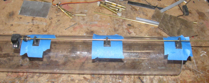
    Mark the tube and cut with grinding cutoff wheel.
    Well that did not go well.
    I cut on the wrong side of the mark and my tube is too short.
    I will have to make another tube.
    Looked around t find I did not have a length of the tube the long enough.
    I will have to pick some up later.

    On to the second dog bone.
    Using tape to mark the tube, I got a good cut with the correct finish length.
    I installed the dog bone end in the tube and drilled and pinned it in place.

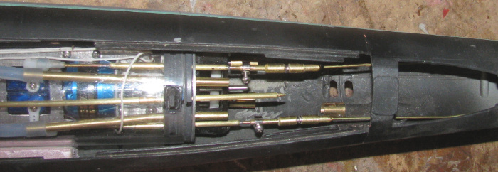
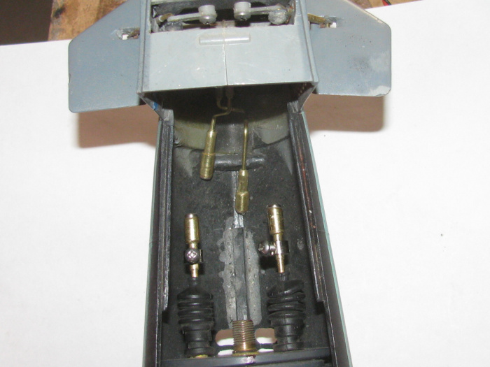
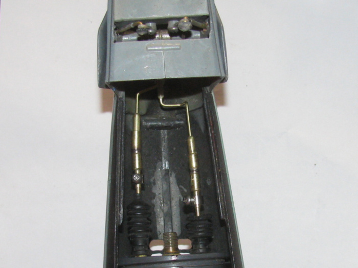
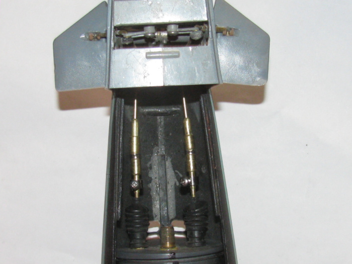
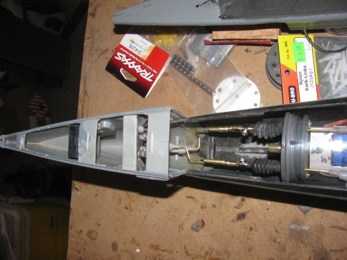
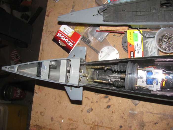
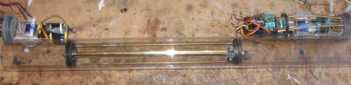
    Test fit in the hull with the cylinder in place with end cap.
    There is not quite 1/8" movement between the dog bone connectors.
    The propeller turns easily.
    I have a good dog bone.

    I have an appointment in town tomorrow so I will go over and see if I can find the more tubing after it.
    Have a 1/2" sample to take with me.

    Comment

    • Ralph --- SSBN 598
      Junior Member
      • Oct 2012
      • 1417

      #47
      July 6th ======================

      I found brass tubing yesterday.
      This morning, I got ready to make a new dog bone extension.
      Of the 4 sizes of tubing I got, I was 1 size too small.
      They did not have the next larger tube.

      So in the shop I found 2 short pieces of the right tube and soldered them together with a brass tube sleeve inside.
      I could not bend them apart so I am going to use it.
      Dog bone extension is complete and tested in the hull.

      Next, I decided to mount the 3 plastic brackets for the ballast tank vent valve control rod.
      I measure and locate where the 3 brackets will go and I tape on the cylinder the areas to be lightly sanded.
      Apply CA to the bottom of the first 2 brackets and place them on the cylinder making sure the valve seal is lined up centered and straight.
      Put the second bracket so the control rod is at the mark on the end of the cylinder to line up with the end cap control rod.
      finish with the third bracket.

      Comment

      • Ralph --- SSBN 598
        Junior Member
        • Oct 2012
        • 1417

        #48
        July 7th ======================

        Got out to the shop early so I could get some thing done before doing real life stuff.

        With the front and rear electronics trays out of the cylinder and on the bench, I connected the battery wires and powered up the system.
        What I wanted to do was center up the rudder and rear planes servos.
        Once centered I put the retaining screw in the servo arms.
        Turned off the power and disconnected the battery wires.
        I didn't want to mess with pulling the battery wires through the ballast tank and stuffing everything in the cylinder.
        With the rear electronics tray disconnected from the batteries, I carefully slide the rear electronics tray in to the cylinder making sure not to move the servos.
        I put the 2 magnetic connectors on the control rods making sure they were centered in the adjustment on the rod.
        Put the cylinder in the hull watching to make sure the alignment bracket hooked the flood hole. (keeps the cylinder from moving)
        I connected the back part of the magnetic connectors on to the front connectors.
        I carefully lifted the rear planes control rod up to the magnetic connector and set it in top of the connector.
        From the side I looked and adjusted the rear planes to level.
        Marked the control rod wire where it sat on the connector.
        Took the rear connector half out and slipped the control rod in to it.
        Checked the mark I put on the rod.
        I had to cut about 3/32" off the rod.
        Slipped it on again and put in the hull and let it connect to the front magnetic connector.
        Holding the control rod with needle nose pliers, I adjusted the control rod while connected until the rear planes where level.
        Then I did the same with the rudder control rod.

        Now I know I can adjust both with the connectors on the end cap centered, I have adjustment on the magnetic connector on the end cap control rods.
        I marked both control rods where the connectors sat.
        Removed the connectors from the control rods and files a few marks in to the control rods for the glue to catch.
        Applied glue to the rear planes ans slid it on. the control rod.
        With the glue the connector moved easily.
        Connected the 2 magnets and adjusted the rear planes to level while holding the control rod coming out of the end cap.
        Did the same to the rudder and got rudder centered under the hull.

        I will leave it all to cure and get to the real life stuff before it get too hot.

        Photo of connectors in place.
        The wheel collars have bolts instead of Allen screws which makes tightening so much easier.
        No stripped Allen sockets or threads.

        Comment

        • Ralph --- SSBN 598
          Junior Member
          • Oct 2012
          • 1417

          #49
          July 9th ======================

          Went out to the shop to gather up tools for the lake tool box.
          It is still cool but going to get hot.

          Before moving the Gato so I could put the tool box on the bench, I thought I might measure for the bow plane retracts and bow planes control rods with magnetic connectors.

          Shorten the control rods coming through the front end cap.
          I have not decided if I will put o-ring seals instead of the rudder boots.
          The boots have been working so I think I will leave them for now.

          Ground the tube with a notch so the set bolt will go through to the control rod. (ones at the end cap)

          Cleaned out the brass tubes so they slipped on to the control rod easily.
          I made new control rods to the bow planes assembly.
          They needed to be much shorter so 90 degree bends where required.


          Testing connectors for travel.
          Bow planes are in the up position.


          Bow plane extended.

          Comment

          • Ralph --- SSBN 598
            Junior Member
            • Oct 2012
            • 1417

            #50
            July 12th ======================

            In the shop very early.
            Temperature gets over 110F by 10am.
            Got home Saturday from the lake gathering to be greeted by 119F on my front porch.
            Animals hibernate in the winter.
            I hibernate in the summer.

            Okay, in the shop.
            I put the rear electronics tray in the cylinder.
            I hooked up the front electronic tray through the cylinder.

            This was easy because the ballast tank frames are not in the cylinder yet.
            Powered up the Tx and Rx.
            Made sure the front servos where on the correct channel.
            Put the cylinder in the hull and linked up the magnetic connectors to the bow planes.

            I needed the Bow plane retract in the stowed position (up)
            I needed the bow planes level.

            Put the Tx controls in those positions.
            Then I slid the magnetic connectors on the bow side until I got the bow planes up and marked the control rod with black marker.
            Got the planes level and marked that control rod with black marker.

            I removed the retract control rod and I made cut marks on the rod with the wire cutters.
            I did this until the rod was tight in the connector.
            I put glue on the rod and pushed it in to the mark.
            The cut marks also hold glue.
            The glue will expand and hold on to the notches.

            Did the same to the pitch control rod.

            Set aside to cure.

            The frames that my cylinder sits on where place for the first cylinder.
            Now that there is 2" plus more inches at the rear of the cylinder, when I push down on the end cap, the cylinder rocks in the 2 frames.
            Easy fix.
            Make a plastic block.
            Shape it to the hull bottom and to the cylinder diameter.
            Measure the end of the cylinder height from the bottom of the hull when in the 2 original frames.
            Test fit plastic block and trim until the end of the cylinder measures the same as without the block.
            Testing includes pushing down on the cylinder.
            Glue it in place 1/2" from end of cylinder.
            Cylinder is now solid in place.

            With the hull block curing.
            The control rods curing.
            There is not much I can do at this point.
            96 F is a good time to stop for the day.

            Comment

            • Ralph --- SSBN 598
              Junior Member
              • Oct 2012
              • 1417

              #51
              July 13th ======================

              I was going to take video of rudder and rear planes.
              Bow retract and pitch control.

              As I installed the bow plane magnetic connectors I could see I had a problem with the retract connector.
              It was too long by about 1/4".
              I put it in the boat and sure enough I could not adjust in the bow planes retracted position.
              Bent the control rod but it was not enough.

              Removed the retract connector from the boat and went on to disasembling the rod from the connector.
              Hoping not to damage the connector tubes.
              Success.

              Using a 1/16" drill bit, I cleaned out the connector for the control rod.
              I cut just short of 1/4" and cleaned up the end of the control rod with the grinding wheel.

              Test fit and measured.
              Applied glue and pushed the control rod in to the connector making sure to get to the black mark.

              This time I clamped the connector and control rod to a steel straight bar.

              What I think happened is as the glue cures it expands and it pushed the control rod out of the connector.

              The other control rods may have done the same but there is enough adjustment that I did not notice if the rod was pushed out a little.
              ======================
              Just remembered I need to go out and get the battery out of the Tx.
              I have ran test so much the low battery beep started up on me.

              Comment

              • Ralph --- SSBN 598
                Junior Member
                • Oct 2012
                • 1417

                #52
                July 14th ======================

                This is with retract link shortened, 1/4".
                Planes up.


                Planes down.


                I did a video of the planes operating.

                Comment

                • Ralph --- SSBN 598
                  Junior Member
                  • Oct 2012
                  • 1417

                  #53
                  =================
                  Back from town.
                  I got a message last night that my Engel's order was at the post office and ready for pick up.
                  16 days from order to in hand.

                  I have three 300kv motors and 2 speed controller.
                  It's like my birthday or Christmas!


                  It will take about 10 minutes to remove the bad motor and replace it with a new motor.
                  Sorry to say, I may not get to it until Friday.
                  Or if I get up early tomorrow before leaving for the day.
                  Never know.

                  Note: the power wires are smaller in sized.
                  I always thought the originals where over sized for the job.
                  Last edited by Ralph --- SSBN 598; 07-14-2021, 06:27 PM.

                  Comment

                  • Ralph --- SSBN 598
                    Junior Member
                    • Oct 2012
                    • 1417

                    #54
                    ===continuing=================
                    Well, we know what happened.
                    Sitting here on the computer with 3 new motors sitting there.
                    JUST sitting there.

                    I could not resist.
                    Took 1 motor and headed out to the shop.
                    It took 7 minutes to remove the old motor and install the new motor.
                    I pulled all the plugs out of the Rx.
                    Ten I plugged in the motor speed controller.
                    Plugged in the power from the speed controller to the Rx.
                    Plugs the 2 battery wires in to the speed controller.

                    This should give me the speed controller and motor.

                    Yep, it came alive.

                    Now the fun starts.
                    I can only get forward from the Tx.
                    Something changed (speed control programing)during all this messing with the motor over the last couple of months)

                    I change wires. (Brushless will change direction by reversing any 2 wires)
                    Okay I have the direction correct but I still only have forward on full stick movement.
                    Bottom to stop and top for full rpm.

                    I came in and did research and that was no help on programming.
                    Other than is is Tx programmed.

                    Back out to the shop.
                    I tried everything I could think of to get reverse to work.
                    After about 20 minutes of failure, I did something and there was reverse with center stop.

                    Don't ask me what I did.
                    I don't know.
                    I was just trying every position I could think of.
                    Remember what I did. . . NO!

                    As the system stands right now, I have throttle in both directions with center stop.
                    I plugged in the rudder,rear planes and ballast air pump motor servos.

                    This means every thing on the rear electronics tray now works correctly.

                    The front tray has always worked so it is just a matter of getting the servo plugs on the correct long wires extensions.

                    I will ask others at the next gathering and I will write it down.
                    ======================
                    I now have to move on to final trim for the ballast tank o-rings.
                    The ballast tank has to go in before I can put the front electronics tray in to stay.

                    I think I just have to clean the bottom of the o-ring grove with some 400 wet/dry sand paper.
                    I will make a wooden block with a tongue that I will put the sand paper on.
                    The shoulders on each side of the tongue will keep ride on the end cap and keep the tongue from reaching the bottom of the o-ring groove.
                    I will then file a little off each side and slowly remove material from the bottom of the groove.

                    Comment

                    • Ralph --- SSBN 598
                      Junior Member
                      • Oct 2012
                      • 1417

                      #55
                      July 15th ======================

                      Today I was working on the ballast tank vent valve control rod.
                      It goes over the main motor and there is clearance but when the motor runs the slight movement of the motor cause the motor to touch the control rod.

                      Looking at it from the side so I could see the control rod where it passes over the motor and watch the clearance, I could see the touch.
                      Not enough to slow the motor but in time it would remove the finish on the motor.
                      Thought about putting a bend in the control rod.
                      But then it might not slide easily during operation.

                      On the bench are parts from the George Washington which has it's cylinder all apart for updating, I see the control rods for the rudder and stern planes.
                      The control rod is 1/8" tubing then down to 1/16" outside the cylinder to the rudder and planes control rods.

                      Idea!
                      Cut a 2.25" section in the middle of the Gato vent valve control rod.
                      Right over the motor where the 1/8" tube will still be in the end cap bushing.
                      The 1/16" rod will go over the motor and then back to the 1/8" tube for the long run to the servo.

                      15 minutes later I have made the modifications.
                      This gives plenty of clearance above the motor.

                      On to the issue with the bow planes retract servo.
                      Took it off the electronics tray.
                      Hooked up and tested.
                      It works fine, most of the time.
                      But then there is a spot where the servo misses a gear.
                      Opened up the servo and found 1 gear tooth with the top 1/3 missing.
                      When the servo gets to that spot and the control stops the movement, the servo will not move the arm until several tries.
                      Easy fix.
                      Replace it with a new servo. (I have a box full of those littel things)

                      With that issue taken care of, time to work on the ballast tank o-ring fit.
                      When I first make the ballast tank end frames, I did not cut the groove deep enough.
                      In the original cylinder after months of sitting on the bench, I see cracks forming all the way around the cylinder.
                      The o-rings where too tight and the cylinder expanding and contracting cause the cylinder to start cracking.
                      The cylinder does not leak, but this was a good time to get a new cylinder and make it longer for more ballast tank volume.

                      I am using the original front end cap but I made a new rear cap due to having to relocate some of the control rod exits.

                      Using my 3" long cylinder test piece, I can slip the ballast tank frames in but there is needed force.
                      So I made the wooden block to deepen the o-ring groove.
                      I have some 320 grit wet/dry sand paper.
                      And it is used and worn down.
                      With sand paper and block I sanded around he frame in the groove.
                      Testing the fit ever couple of minutes.
                      It took about 15 minutes to get the first o-ring to slip in with very little effort andn seal the frame to the cylinder.
                      Tested by blowing in to the end of the cylinder and putting my finger over the through brass tube to seal the cylinder.

                      Did the second ballast tank end frame the same way.
                      This one took less sanding to get the same results.

                      While testing the electronics, I could see the out put shaft for the gear box rubbing on the aluminum compression plate for the seals.
                      I removed the gear box and filed 3 of the 6 holes a little bigger for control rod clearance.
                      I found that the gear box was too tight on one of the gears.
                      Files a little on the bushing that goes through the gear.
                      This fix it right up.

                      Reassembly will be tomorrow.
                      I got to go for the day.
                      Also I have 1 plastic bracket to glue on permanently.
                      It was glue on temporarily with just 2 little spots of glue.
                      Now it needs to cure.

                      Good place to stop for the day.

                      Comment

                      • Ralph --- SSBN 598
                        Junior Member
                        • Oct 2012
                        • 1417

                        #56
                        July 17th ======================

                        Got a late start out in the shop.
                        Was already getting hot.

                        Got to do something, I wasn't in the shop yesterday.
                        I cleaned up the rear end cap and greased the 3 o-rings and 1 cup seal.
                        Put them in to the cap seal recesses.
                        Slipped the aluminum compression plate over the control rods and water inlet/outlet tubes.
                        Put the gear box on and 2 bolts.
                        Test ran the rear planes, rubber and motor.
                        There is binding on the motor extension shaft.
                        Close inspection I can see the new stainless Allen screw holding the motor to the extension shaft is touching the aluminum motor mounting bracket.

                        This requires disassembly to fix..
                        I need to cut more off the bracket to let the set screw pass by the bracket.

                        Cutting and rounding the aluminum edges off.
                        Reassembled.
                        Testing the motor again and tightening mounting bolts while moving the motor on the 2 brackets to get the least resistance.
                        Found the spot.
                        The motor turned by hand will coast when let go.

                        Check all controls on the rear electronics tray.
                        It will soon be in the cylinder and hard to gt to without full disassembly of the cylinder.

                        Move on to the ballast tank frames.
                        This unit slides in to the cylinder.
                        It has to pass all the flood holes in the cylinder.
                        I took some time to clean the edges up on each flood hole.
                        I want to make sure the ballast tank frame o-rings do not get caught or cut as they pas the flood holes.
                        Well actually only the back end frame moves over the flood holes.

                        Cleaned the flood hole edges greased the o-rings and placed them on the ballast tank frames.
                        Now to slide the frames in to the cylinder.
                        Front the front has the least distance to travel.

                        Done.
                        Looking at the o-rings, I see the grease line all the way around the cylinder.
                        Put the two small bolts that hold the vent valve on the top of the cylinder.
                        This has some silicone glue.
                        Going to let it sit until tomorrow.
                        It's hot in the shop now.
                        So leak testing tomorrow will be first.
                        This is easy to do.
                        Put a piece of tape over the vent body hole.
                        Turn the cylinder upside down and put water in the cylinder through a flood hole until full.
                        Let it sit for an hour or two and see if the water level drops or the table it's on is wet.

                        Here is the cylinder with the frame inside and the electronics trays sitting along side to make sure there is room at both ends.

                        Comment

                        • Ralph --- SSBN 598
                          Junior Member
                          • Oct 2012
                          • 1417

                          #57
                          July 18th ======================

                          The cylinder was brought in to the house.
                          Tape was put over the vent valve body outlet hole.

                          With the cylinder upside down, water was put in the ballast tank.
                          Set the cylinder on the kicten counter over the sinks.

                          After about 2 minutes I saw water dripping.
                          Not wanting to move the cylinder, I got my trusty mirror and looked under the cylinder to trace the water back to it's source.

                          Was not a hard leak to find.
                          At first I thought the water was coming from behind the tape.
                          Looking closer, I see that the vent valve body is not sealed to the cylinder on one side.
                          Easy enough to fix by removing the valve body.
                          Cleaning the silicone glue from it and reapplying the silicone glue.

                          So I left the cylinder on the sink counter to watch for other leaks.
                          Only place it can leak is around the 2 ballast tank frames and o-rings.
                          So far no leaks from there.

                          Going to leave for about 2 hours.

                          Oh, the leak at the valve body, I sealed with a little silicone grease so I could continue the tank frame o-rings leak test.

                          Comment

                          • Ralph --- SSBN 598
                            Junior Member
                            • Oct 2012
                            • 1417

                            #58
                            July 19th ======================

                            I have removed the ballast tank vent valve.
                            Cleaned all the silicone glue from the valve body, bolts and cylinder.
                            Lightly sanded the cylinder for better bonding.

                            Looking at the silicone on the bottom of the valve body, I do not see any gaps in the layer.
                            Okay, time to look closer. (10X loop)

                            Possible gap in valve body itself on the back panel piece.
                            Cover the outlet hole on the valve body.
                            Using a brass tube and rubber fuel hose attach to inlet hole on valve body.
                            Blow in to hose.
                            Sure enough the back panel on the valve body has a gap in the layers of plastic sheet.

                            There was also an air leak on the port side mounting bolt of the valve body.

                            The fix was to build an new valve body and make the base longer.
                            Longer so I could move the port side mounting hole on the cylinder.

                            The leak was threads through the cylinder not being cut correctly.
                            I use stainless bolts to cut threads in my cylinder.
                            It appears, I use a slightly large bolt to make the threads then uses a smaller bolt to install.
                            I looked for the lager bolt but it is no where to be found.

                            So I will fill the over size hole.
                            I will drill the new hole to match the new valve body.
                            Make sure I use the correct bolt to cut the threads.
                            This part of the fix is done.

                            The valve body base is made and drilled.
                            The valve body is in the vise while curing.

                            I will drill the valve body for the inlet and outlet openings later today.

                            Back later
                            -------------------------------
                            The ballast tank vent valve body is complete.
                            Drilled and assembled.
                            Like all plastic parts, it is in the vise to cure.
                            Last edited by Ralph --- SSBN 598; 07-19-2021, 03:55 PM.

                            Comment

                            • Ralph --- SSBN 598
                              Junior Member
                              • Oct 2012
                              • 1417

                              #59
                              July 21st ======================

                              The last 2 days have been interesting.
                              First, everyone's break from reading my almost daily posts is over.
                              My internet connection is through a small 9" dish and it stopped receiving yesterday.
                              The repair tech came this morning and replaces a couple of parts and I am on the internet again.

                              Progress report.
                              Yesterday, I completed the ballast tank valve body repair and reinstalled it on the cylinder.
                              The cylinder is currently in the kitchen up side down with the ballast tank filled with water while I watch for leaks.
                              After the tech left, I was going to go out to the shop and see about stuffing the electronics in the cylinder.

                              Opened the back door and the heat rushed in.
                              I decided to wait until early tomorrow morning to work in the shop.

                              I think I am at the point to put everything back in the cylinder and do water testing.
                              Then in to the hull to trim test.
                              ------------------------------
                              I did not realize how much e-mail and other messaging I get until I was without for about 22 hours.
                              I need to trim some of that down.

                              Comment

                              • Ralph --- SSBN 598
                                Junior Member
                                • Oct 2012
                                • 1417

                                #60
                                July 22nd ======================

                                Well the ballast tank water leak test went far better than I thought it would.
                                Yesterday, I filled the ballast tank with water and left it sitting in the kitchen so I watch for leaks.
                                After the net tech left, I got busy with other stuff.

                                I did not get back to the cylinder and the leak test.
                                This morning, the ballast tank is still full of water and there are no signed of water leaking around the ballast tank frame o-rings or from the vent valve body.

                                I think it is safe to start putting everything in to the cylinder.
                                All the electronics has been bench tested and a couple of issues have been corrected. (plugging in a servo to the Rx backwords was the worst of it.

                                The problem now is the heat coming on so early in the morning.
                                It is beating me up more than I would like.

                                Comment

                                Working...
                                X