Gato build has resumed.

Collapse
X
 
  • Filter
  • Time
  • Show
Clear All
new posts
  • Ralph --- SSBN 598
    Junior Member
    • Oct 2012
    • 1417

    #16
    June 4th ===========================

    Yesterday's trip to the big city had me coming home with a new length of cylinder tubing for the Gato.
    Today at the post office, there was a small package which contained 2 pinon gears.

    I took the gears out to the shop and placed on the work bench.
    How ever I will not be working out there today.
    11 am it was 102F out there.
    Tools on the bench were hot to the touch.

    The plan is to get up early (like 5am) to get some work done out there.
    See how long I can go before the heat chases me out of the shop.

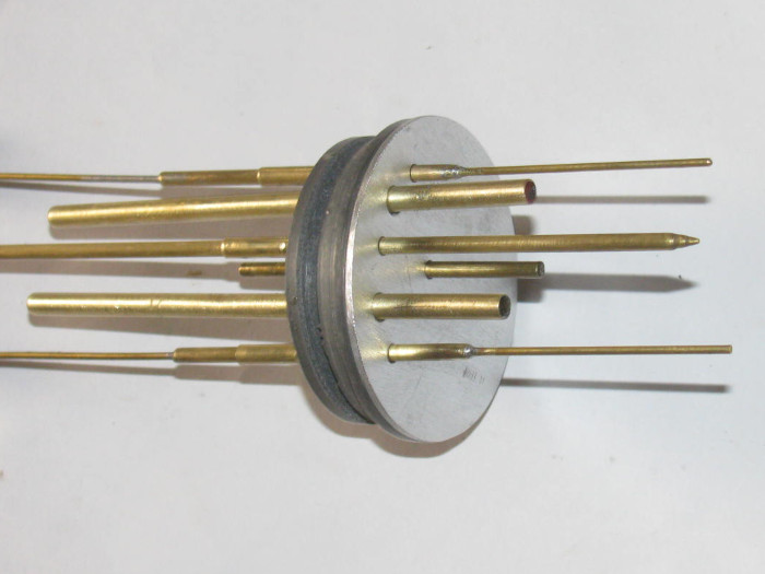
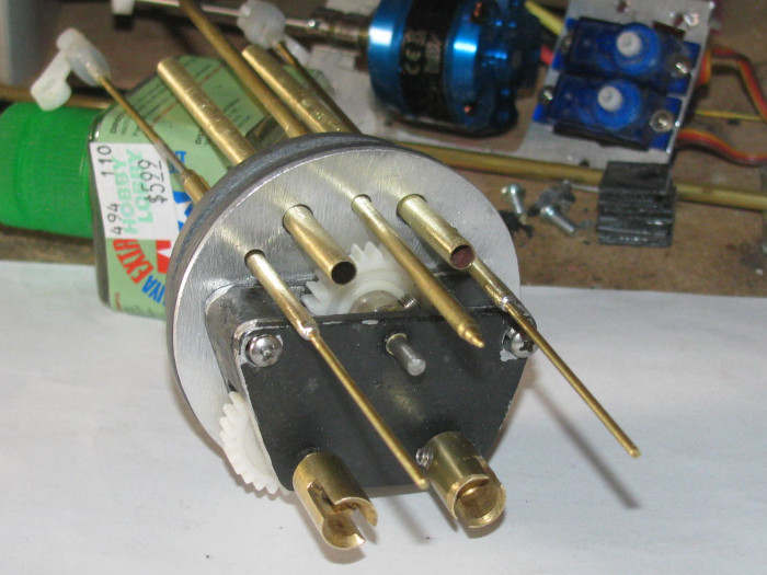
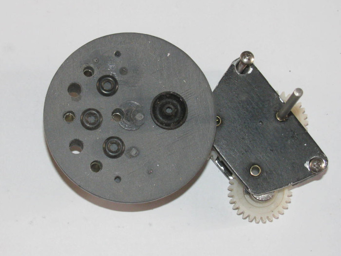
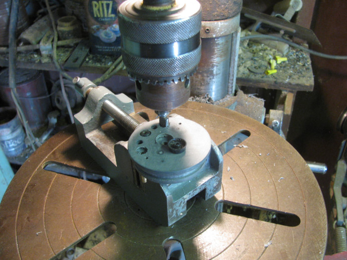
    I did bring the gear box parts in to the house so I can do measuring and marking later today.

    Comment

    • Ralph --- SSBN 598
      Junior Member
      • Oct 2012
      • 1417

      #17
      June 5th ===========================

      The new cylinder is cut to length.
      Fitted in to hull so the location pin is in the correct ballast flood hole.
      Flood holes drilled and cleaned up.

      Remove ballast tank frames from original cylinder.

      Drilled rear end cap for the motor shaft bushing and installed the bushing.
      (I can mount the motor on the back of the end cap)
      The rest mounts to the gear box.

      I was laying out the location for the other 3 gears when I discovered the new pinon gears are not the correct tooth pitch. (too small)
      The original 3 gears are the same but the packaging and web site gave no pitch.
      I did a chat with Chris at the company and learned the the gears I got are drive gears and they have no pinons that will work with them.

      So I am on the search for new gears, or a pinon with teeth that will engage.
      I have a backup plan.
      I have 4 of these drive gears and can use them to make this work.

      The reason I wanted to go with the pinon was to get a 2 to 1 gear ratio so the motor could run faster and the propellers would run slower.
      The motor tends to cog a very low speeds.
      But not having run the boat, I do not know what the slow speed will be on the motor to get the cruise speed.
      ----------------------------
      Can anyone point me towards a supplier of small nylon gear?

      Comment

      • Ralph --- SSBN 598
        Junior Member
        • Oct 2012
        • 1417

        #18
        I braved the heat and went back out to the shop.
        I wanted to get the cylinder in place and the location pin in the correct spot.
        Turned out the pin I made a day or so ago was too short and off center.

        So I made a piece of plastic to glue on top of the existing pin and go up in to the ballast tank by 1/8".
        Got it made.
        Put a slot in it for the air outlet brass tube.
        Put the cylinder in and looking through it I centered the flood hole on the hull over the pin.
        I could see where to put the added piece.

        Removed the cylinder.
        Applied bonding cement to both the pin and the part.
        Placed the part on the pin and held it for about a minute.
        Carefully slipped the cylinder in to see if I got the part located right.

        In the right place. I just needed to twist it about 1/16" to square it up to the hull center line.

        While making the new cylinder, I found an issue I did not see with the old cylinder even though the issue was there.
        The front of the cylinder was not sitting in the hull saddle.
        It was resting on top of one of the ballast blocks.
        This made the front of the cylinder high by 1/4" actually.

        This put part of the cylinder above the waterline. (not good for trimming)

        This ballast block is not glued in yet.
        It was one of 2 blocks I left loose so I could move them during trimming.
        What to do?
        That was easy.
        Take the lead block out to the steel work bench out side.
        Using a 24 oz ball peen hammer, pound the block thinner.
        Measured the hull/saddle height so I would know how much pound I needed to do.
        Not much with 24 oz hammer.
        Got it thinned out giving it a little gap now.
        Took the ballast block over to the big vise.
        I have short pieces of steel pipe I use to shape ballast blocks.
        Pick one that has a curve that in close to the hull curve.
        Put the block across the vise jaws and place the pipe on top of the block.
        A couple of good wacks and the block now has a nice curve to it.
        Took it in to the shop for a test fit.
        Needs another wack wit the hammer and pipe.
        Back in the shop.
        Place the block down in the hull and carefully place the cylinder in the hull.
        I can see the gap between the cylinder and block.
        I pushed down on the cylinder at the saddle frames.
        No More rocking.

        Now I have to get back to try finding gears or make the decision to use what I have and move on.
        2 to 1 would be nice but I know 1 to 1 will work.

        I even check to make sure it would fit after moving the propeller output shafts on the gear box.

        In the original gear box the extra gear was above the output shafts.
        Now they will be under the output shafts.
        The main motor is lower in the hull now by about 3/8". (maybe more)

        I going out to the shop to close it up.
        I will get a photo of the ballast block in place.

        The block on the left is the one I pounded thinner to fit.


        Here the cylinder is in place to check for clearance.
        Last edited by Ralph --- SSBN 598; 06-05-2021, 06:33 PM.

        Comment

        • Ralph --- SSBN 598
          Junior Member
          • Oct 2012
          • 1417

          #19
          June 6th ===========================

          I spent a lot of time researching gears.
          What I found is not good.
          The size is not something stocked.
          What I found were $18 each and up to over $90, plus shipping.
          There are custom makers but they do not give pricing.

          So I went to the shop and started on plan B.
          Using the 4 gears I have.
          Easy enough to make them work.
          The problem is, using these 4 gears covers almost all the end cap.
          There would be no way to get 3 control rods and 2 water tubes in the end cap.

          When I placed the gears so I would have room for the control rods and water tubing, 2 gears stuck out past the esge of the end cap so far that they would hit the hull.

          Okay, now I know what I am up against.
          I reassembled part of the original gear box.
          The issue with that gear box was the angle of the dog bone shafts.
          With the cylinder and the end cap in place, I held the gear box against the end cap and lined up the dog bones at both ends.
          In the original position the output shafts where very low in the hull.
          This was with the motor in the center of the end cap.
          The new gear box was to get the motor down lower by 3/8" to 1/2". (with out a small pinon, this will not work)

          Anyway, I moved the gear box on the end cap until the 2 dog bone shafts where parallel to the waterline. (only reference I had)
          This change the dog bone angle to where it was much less of an angle than original.
          I marked the end cap with a pencil across the top of the gear box frame.

          Measured the difference from original to new location of gears.
          I was surpirses to see abut 3/8".

          Tow things made this happen.
          I moved the gear box up and remember yesterday I fixed the cylinder to sit in the saddle frame correctly.
          This brought the rear end cap up about 1/4".

          I drilled the motor shaft through bushing hole in the end cap.
          Originally I was going to cut the cup seal recess this morning after layout.

          The bushing was cut and is now glued in the end cap with the gear box sitting in place with weights and the shaft going through to keep everything straight.

          I moved on to modifying the gear sizing bushings.
          The hole in the center of all the gears is too big.
          With a brass tubing I shimmed the hole down to the 1/8" shaft size needed.
          I needed to drill a hole in the bushings so the grub screw could go through to the shaft pieces.
          Did than and cleaned them up and fitted them.
          Now the grub screws easily go through to the shaft.

          The original gear box never looked right but the gears are in the correct location
          With calipers in hand, I measured the gear box frame.
          I have shaped it by hand and eye.
          Turns out one side is 1/16" wider than the other.
          I will fix that after I get the gear box assemble again.
          Little bit of belt sander ought to do it.
          This will also lighten the gear box helping with trimming.

          After so much time looking for gears, I think I will stay out of the shop now.
          The glue on the gear box needs to cure anyway.

          I made the cylinder 1" longer than original.
          I may have to cut about 1/2" off.
          Still a net plus on the length.

          Comment

          • Ralph --- SSBN 598
            Junior Member
            • Oct 2012
            • 1417

            #20
            June 6th ===========================

            The shape of the gear box can be modified.
            This will make more room for the 3 control rods and 2 air intake tubes.

            While assembling the gear box, I check each shaft for square to the box and end cap.
            The motor shaft is a little off through the end cap so I will be correcting that.
            Easy enough to do.
            Find a brass 1/8" rod to put through the bushing and then heat the rod with the soldering iron.
            This will soften the end cap PVC.
            Once hot, I can twist the rod and change the angle of the bushing through the end cap.
            I have a fixture that will hold the rod while down pressure on the end cap will push the cap down on the face of the fixture which is square in all directions.

            The gear box has been reassembled and glued.
            It is in the vise until cured.
            The glue holds it together but there are 2 stainless screws that go through the gear box to the end cap which hold the gear box frame together as well.

            Cut a piece of the aluminum sign that will cover the end cap.
            I have decided to go back to using o-rings instead of the rubber boots.

            The rubber boots where strong enough in trying to go back to there natural cast shape they were putting pressure on the servos.
            These little servos would fail after some time because of the rubber boots.
            So it's back to the tried and true o-rings in the end cap with a plate over them to squeeze slightly and hold them in place.
            I have 10 years experiences with o-rings under flat plate in end caps.
            Not one ever leaked or failed.

            Besides, I think the o-rings and plate are actually lighter than the rubber boots.

            Something has come up and I will be out of the shop.
            I did glue all the parts I could think of so they can cure before I get back to the shop.

            Found some small magnets I use in the Skipjack on the sail planes.
            I think I will try them on the bow planes.
            If they work out, I will try them on the 3 control rods at the back.

            Comment

            • Ralph --- SSBN 598
              Junior Member
              • Oct 2012
              • 1417

              #21
              The fit for the crooked bushing through the end cap.
              Before heating the bushing, I tried using a drill bit the size of the tube outside diameter.
              Placed the end cap over two metal blocks and let the bushing sit over the gap between the blocks.
              Using the drill bit back end, I put it the hole in the end cap where the bushing is.
              The bushing only goes half way through because I will be cutting a recess for the cup seal.
              A light tap of the hammer on the end of the drill bit, the bushing moved.
              Another tap and the busing moves again.
              Third tap the bushing is clear of the end cap.

              Place a [piece of stainless motor shaft in the vise using the V cut to hold it square.
              I check with my little square.
              It looks good.
              Cleaned the bushing off with the grinding wheel to get to clean brass for the glue.
              Applied glue and reset bushing in to end cap.
              Flush on the inside.

              Wondering why the hole was crooked.
              I went out to the tool shed and looked at the drill press.
              Found the problem.
              Total operator error.
              I drilled the hole alright but I did not check the drill press table clamp tight.
              The table is not square if the clamp is not tight.
              So I think from now on I will tighten the clamp before leaving the shop or swing the table away from center making it necessary to move the table which would make me tighten it before use.

              Looked for magnets in my parts bin.
              Only have enough for 1 and a half control rods.
              I may go to town tomorrow and get more.
              Moving along every day. Progress!

              Comment

              • Ralph --- SSBN 598
                Junior Member
                • Oct 2012
                • 1417

                #22
                June 7th ===========================

                More measuring and test fitting.
                The bushing could be moved using heat but when measuring again, I found a piece of scrape masking tape in the bottom of the hull.
                Yep, it was holding the front of the cylinder up so my previous measuring was wrong.

                So I started measuring, over.

                The main shaft bushing needed to be moved up 3/16".
                So heating the bushing will not do.

                Put the cylinder with end cap in the hull making sure it is sitting down on the saddles.
                Hand held the gear box against the end cap.
                Moved the gear box around until the dog bone connectors where straight inline with each other.
                I used a sharp metal scribe to mark the to location of the gear box.
                I have been using a pencil but that has turned out to make a line that is too thick and placement is not correct.

                Took the cylinder out of the hull and removed the end cap.
                Placed the gear box on the scribed line.
                Measured to get the 2 out put shafts centered on the cap.
                This will make the motor shaft off center by 1/16" or less.

                Drilled the end cap for the bushing.
                With a shaft through the bushing and gear box bushings, I located the 2 mounting holes.
                These holes will have bolts that go through the gear box, seal plate in to the end cap.

                Marking these holes took some time as everything moves.
                Finally I got some small pilot holes drilled.
                Looking through the gear box I could see the pilot holes and knew which way to make the hole so it would be centered.
                Did this for both bolts.

                Using a small drill with a short piece of brass tube over it, I drilled the small holes in the end cap which will be threaded by the bolts.
                The brass tube over the drill bit holds the bit center of the hole through the gear box.
                Even it it moves off center a little the tube keeps the hole centered enough for the bolt.

                I got the gear box, seal plate mounted on the end cap.
                Not tight, I could move the gear box and or the seal plate to make sure the 3 shafts move freely.
                Slowly tightened up the 2 bolts and checked the shafts turning until the bolts where tight.

                Checked the bushing in to the end cap over the drive shaft.
                It took several tries but I finally got the gear box tight and the shafts turn freely with the bushing in.

                Remove the bushing and apply the glue. (Gorilla glue expands and will fill the gap in the end cap)
                The shaft through the gear box and end cap will hold the bushing in place while the glue cures.

                Having gone back to the original gear box, the original electronics tray should fit right in with maybe a little modification to the mounting hole locations. (I shorten the tray by 1/2" or so)

                Tomorrow, on to the electronics tray assembly.

                Comment

                • Ralph --- SSBN 598
                  Junior Member
                  • Oct 2012
                  • 1417

                  #23
                  June 9th ===========================

                  This morning, I finished installing the last bushing in the end cap and gear box.
                  Lined every thing up and applied the glue to the bushings.
                  Make sure every thing turned and set it on the bench and weighted it down so it does not move.

                  While messing with the end cap/gear box, I was looking at the ballast tank frame.


                  I set the electronic tray sections together on the bench to measure over all length.
                  It has changed because I cut a little off here and there to make the tray shorter.
                  I also left the cylinder longer so I could cut it after the electronics tray was compele.

                  The electronics tray is now about 1.3" shorter.
                  I had lengthened the ballast frame about 75" longer a while back.
                  My quick water testing last week says it might be okay but I could lengthen the frame again while it is out of the cylinder.
                  So after messing withe end cap/gear box, I did just that.
                  I unsoldered the frame spreaders and lengthen them 7/8".
                  Extended the wire through tube as well.

                  The boat is an air pump boat so the ballast tank will be completely empty or completely full.
                  No baffles used.
                  But if I try to do decks awash, I will have to have the boat at a steady speed to keep the water in the ballast tank still.

                  Worst case, I have to remove the ballast frame later and add baffles.
                  No a big job at all.

                  Comment

                  • Ralph --- SSBN 598
                    Junior Member
                    • Oct 2012
                    • 1417

                    #24
                    June 11th ===========================

                    Yesterday at the VA seeing doctors on followup surgery stuff.
                    Everything is good.

                    Back this morning to VA for some paper work corrections.
                    This also went well.

                    No work yesterday on Gato.
                    Today, I worked on mounting stuff.

                    First I made sure the motor shaft through the gear box was straight and turned freely.
                    Next I measured for the motor electronics tray end cap bracket.
                    Drilled 2 holes in end cap. (1/4" deep)
                    Installed this bracket.

                    Put the electronics tray that the motor is actually mounted on on to the end cap bracket.
                    2 bolts and checked with square to get straight.
                    Tightened bolts and made sure motor shaft turns freely.
                    In one try.

                    Next I plan to install the 2 servos to this electronics tray.
                    I need them there to measure for new holes in the tray that will bolt to the air pump part of the tray.
                    I shortened that tray by almost 1/2" so new hole locations is needed.

                    Tomorrow, I think I can get a few hours in the shop.
                    Undisturbed hours.

                    Comment

                    • Ralph --- SSBN 598
                      Junior Member
                      • Oct 2012
                      • 1417

                      #25
                      June 12th ===========================

                      I have been assembling the rear electronics tray.
                      It is in two parts.
                      The rear tray is the motor and 2 servos for rudder and rear planes.
                      I shortened that tray about almost 12".
                      All the parts fit just fine.

                      The forward tray has the 2 air pumps and a an actuating servo.
                      It also has the speed controller, and pitch controller.

                      The motor section was test fitted to make sure the motor will slide in and not touch the cylinder wall.
                      Then the air pump section was slid in to check clearances.
                      All good.

                      Now I have to figure out how to connect the two trays together so they slid in and out together.
                      The new motor location has changed how the 2 trays meet.
                      This means I need to figure out a new connection bracket.
                      The original plastic parts will not work.
                      I know this because I have already broke them off while trying to connect the 2 trays.
                      I am thinking I might try making an aluminum L bracket for the motor section because the motor section is an aluminum tray.
                      Then make a solid block of plastic I can bond on to the air pump tray.
                      Then I can use 2 small screws to mate the 2 trays together.

                      I spend some time this morning going from hardware store to hardware store.
                      Auto parts store to auto parts store looking for wire cut to length.
                      Most would sell me a package of wire but it was 30' and $9 each.
                      I need 30" of 2 colors.

                      I have an old trailer out back, I should crawl under and see if I can cut some wire off.
                      The trailer has been sitting for about 20 years.
                      Maybe more.
                      The wire may be too brittle.

                      I might have to use speaker wire and double it up.
                      =============================

                      I am finished for today.
                      Getting hot in the shop.

                      I was mounting the motor to the end cap.
                      Then trying to align the air pump tray to the motor tray so I could build some sort of bracket to hold them together.

                      I have a short piece of cylinder for testing fit. (about 10" long)
                      I can see through to line things up and then remove them to make the bracket.
                      I made 4 brackets in all.
                      Each one fit fine in the test cylinder but would bind the motor shaft in the boat cylinder.
                      This was becoming a problem.

                      Then on test 4 the bracket fit fine in the test cylinder and it fit fine in the boat cylinder.
                      That is until I put the boat cylinder in the hull.

                      WHAT?
                      It did not fit. ? ? ?
                      Looking down through the cylinder I could see the problem.
                      The cylinder pin in the hull was lining up with the ballast floor hole.
                      Took the cylinder out removed the motor tray and turned the cylinder around.
                      Put the motor back in and crap?
                      The motor binds up again.

                      Something is not lining up and is causing the motor bracket to twist and bind.

                      Took the motor tray out.
                      I stood the cylinder on end on the work bench so I could look at the motor tray.
                      Reaching for a file, I see the problem. Big as Lift!

                      The boat cylinder is not standing straight up.
                      I turned it over and then the cylinder stood straight up.

                      Okay. This is where I think of all kinds of names to call myself.
                      I had made the assumption the factory cut end was square.
                      Using 2 small metal square, I checked both ends of the boat cylinder.
                      The end I cut was square.
                      The end the factory cut was almost 1/8" off square.

                      Out to the tool shed. (where the band saw lives)
                      I set the cylinder in the band saw vise and made sure it was sitting flat on the table.
                      I set the cylinder to cut 5/16" off the long side I had marked on the work bench.
                      I started the saw and I let it down but I held the weight so it would not cut by just dropping because of it's weight.
                      I slowly made the cut.
                      Out of the saw and checking with my square.
                      The end is not square.
                      Yes, I checked the other end to make sure I cut the correct end.

                      I caused this problem because I did not check both ends of the cylinder for square.
                      It would have saved me about 2 hours of making small brackets when the first one will work.

                      I got the two brackets that hold the motor tray to the end cap installed.
                      The motor turns freely by hand.

                      I dropped a couple of bolts and one of the nuts on the floor.
                      I found the bolts but I could not find the nut.
                      I am using small bolts for this.
                      The bolt is 1/4" long and the nut is not 1/4" across. It is smaller.

                      So after I got the tray problem fixed, I moves a few things and swept the floor.
                      Under the bench and around where my milk crate chair sits.
                      As I made the pile of dirt and plastic and brass filings, I see the nut.
                      All is good with the world today.

                      More tomorrow.
                      Last edited by Ralph --- SSBN 598; 06-13-2021, 02:55 PM.

                      Comment

                      • Ralph --- SSBN 598
                        Junior Member
                        • Oct 2012
                        • 1417

                        #26
                        June 13th ===========================

                        Today, I worked on getting the through tube bushing for the control rods through the end cap.
                        I know it shouldn't take very long.
                        But it does because I put a recess in the end cap for each o-ring.
                        Rudder, rear planes and ballast vent valve.

                        The brass tube bushing does not go all the way through the end cap.
                        They stop short about 1/8" from going all the way through.
                        I use the bushing to guide my recess cutter.
                        The cutter is mounted on a 1/8" brass rod.
                        Both shaft seal cutter and o-ring cutter are on the same shaft.


                        How I made the cutter. ( along time ago)


                        I also drill the 2 holes for the air inlet/outlets.

                        Cut the brass tube bushings and cleaned them up so the control rods would slide through on their own weight. (no effort)
                        Before gluing them in the end cap, I make the tube for the depth to push them in to the end cap.
                        Between the make and the end of the cap end of the tube, I grind notches around the tubes for the glue to get in to.
                        The glue will expand during cure and this gives the glue something to hold on to.

                        At 11:20am, the temp in the shop has past 100 F.
                        I am getting old and I no longer feel the need to try and push my way through working on any thing.
                        Except maybe lunch.
                        So closed up the shop with the end cap in the vise to hold it straight while the glue cures.

                        Comment

                        • Ralph --- SSBN 598
                          Junior Member
                          • Oct 2012
                          • 1417

                          #27
                          June 14th ===========================

                          I have not gotten to making the o-ring cutter yet.

                          Instead I drilled the pressure plate that will hold the o-rings and cup seal in place.


                          Test fitting all the control rods, air inlet/outlet tubes and main motor shaft through the end cap and the pressure plate.


                          The pressure plate will be held on and down with the gear box mounting bolts.
                          End cap, pressure plate and gear box assembled. ( no seals yet)
                          Rudder, rear planes control rods and ballast tank vent control rod in place.


                          Now I will make the o-ring recess cutter.

                          Comment

                          • Ralph --- SSBN 598
                            Junior Member
                            • Oct 2012
                            • 1417

                            #28
                            June 15th ======================

                            The cutter was made.

                            Seals sitting on end cap.


                            The motor shaft seal recess is cut.
                            The 3 control rod seal recesses curt.
                            Cutter still in last cut.


                            Checking alignment.
                            All control rods, motor shaft and air inlet/outlets pushed through seals.
                            Air tubes get glued in later.


                            Test aluminum cover plate.
                            Looks like it will do it's job with 2 bolts holding the gear box and the cover plate on.

                            Comment

                            • Ralph --- SSBN 598
                              Junior Member
                              • Oct 2012
                              • 1417

                              #29
                              June 16th ===========================

                              In the shop.
                              It's getting hot very early today.

                              I am gluing plastic parts together and the cement is drying before I can mate the pieces.
                              I am having to put lots of cement on so it is still wet when I put the pieces together
                              Still drying before I can get them mated straight.

                              Went with a bigger brush which seems to put enough cement on to stay wet for 10 seconds or so.
                              I am using 2 pieces of 1/4" wide by 1/16" thick by 5" long.
                              I am making a plastic ring that fits inside the 2.5" cylinder tube.
                              Using a short piece of tube I am putting the 2 cemented pieces together and quickly putting them in the cylinder to make a ring.

                              The ring will be mounted to the air pump section of the electronics tray.
                              The tray keeps tilting as I hook the rubber air hose to the pumps.
                              The ring will go on the tray and hold the tray down and level in the cylinder. (I hope)

                              Until I can keep the 2 trays level when joined together, I can not move on.

                              Got the plastic pieces together and in the cylinder section.
                              Clamped with spring paper clips.

                              Okay, now that that is out of the way, I measured the air inlet and outlet brass tubes.
                              I need the length of brass tube in the cylinder to be just so so the rubber air hose will connect the pumps manifold to the through cap tubes.
                              Measured and marked.
                              Applied glue and push the tubes through the end cap.
                              Cap held in small vise.
                              tubes are taped to hold the angle straight and the other end is weighted to hold tubes correctly.

                              Checking thermometers, it's 112 F on my front porch and 106 F in the shop.
                              I think I am done.
                              I have cooler in house and just a big fan in the shop.
                              House wins.

                              I think I will order some cylinder magnets ans see what I can do in the way of making magnetic control rod ends.
                              Seems simple enough.
                              I will make a plastic jig to hold magnets and allow pouring epoxy in to make the cover and control rod end.

                              Comment

                              • Ralph --- SSBN 598
                                Junior Member
                                • Oct 2012
                                • 1417

                                #30
                                June 18th ===========================

                                Yesterday was real stuff to do.

                                This morning I was in the shop by 8 am.
                                Already very warm.

                                I started with the forward electronics tray. (air pumps and servos and such.
                                When I put the tray in the cylinder, it would sit high at the back end.
                                This caused misalignment wit the motor tray.
                                The motor tray is mounted on the read end cap.
                                The misalignment caused the rear tray to bind and not sit tight against the end cap.
                                The top was about 1/4" from touching the cylinder.

                                Using my short cylinder piece, I put both trays in from opposite ends.
                                I could watch the 2 trays come together.

                                I made a plastic frame on Wednesday.
                                Basically a circle that would hold the tray down level at the back.
                                I worked on it until it fit and the tray was now level.

                                Sliding the motor tray in I can see the gap between the 2 trays.
                                l can make 2 plastic blocks to fill this gap and keep both trays level. (gap is not quite 1/4" on each side)
                                Might make an aluminum frame piece for the offset.

                                Now The problems start.

                                I tightened the motor mounts.
                                There are 2.
                                1 mounts to the end cap and is an L shape.
                                The other is the flat long section with the motor and 2 servos.
                                The motor turns freely on the tray mount.
                                When I put the tray on to the end cap bracket, the motor turns freely.
                                That is until I start tightening bolts.

                                I put it on and checked it.]
                                I took it off and made small bend adjustments.
                                Almost 2 hours of this.

                                Finally I came to the conclusion that the connector between the motor and shaft extension is not completely centered.
                                When I turn the motor off the end cap, It looks straight as it turns.
                                Then I finally put the tray in a small vise.
                                Now I can measure the shaft to the bench top.

                                Well you wouldn't think it but the shaft is off center by 1/64" or less. (my ruler does go down any more than that. Should have use a micrometer)
                                I seems that my through end cap bushing is very close to the size of the shaft and does not allow the shaft to move that 1/64".

                                Okay, what I did is I tightened the L bracket to the motor tray making sure the motor turned freely.
                                As I tightened the bracket to the end cap, there is a point where the bracket goes tight and flattens out on the end cap.
                                This is where the motor gets harder to turn. (not good)
                                I Moved the bracket here and there.
                                No luck getting the binding out.
                                If I untighten the bolt just a little, (less than 1/8 turn) the motor frees up and turn nicely.

                                Okay. With the bold loosen, I can not move the bracket but I can see it rocking back and forth as I turn the motor.

                                Solution.
                                Remove bracket so I can get under it.
                                I put a small bit of silicone glue on each end and in the middle. (talking about 1/8" square blobs)
                                Now I reinstall the bracket testing the turn of the motor.
                                When the motor binds up, I backed the bolt out 1/8 turn.
                                Motor freed up.

                                I will let this cure and I should end up with a rubber gasket between the end cap and bracket.
                                This will allow the bracket to move slightly.

                                When I make the connector brackets from the motor tray to the air pump tray, I will use small rubber square on the bolts.
                                I might even make the space blocks out of rubber.
                                This will let the motor tray move and the pump tray will not put pressure on the motor tray.
                                I will over size the bolt holed so the air pump tray will more or less float up and down but not back and forth.
                                I just need the 2 trays to slide together in and out of the cylinder.
                                The 2 air hoses may do the trick.
                                They fill the end cap tube to air pump tray gap which is all of 1/2".

                                The weather here has turned ugly.
                                Last night I had lightning without thunder.
                                There were 1 minutes burst of big rain drops for a minute or two at a time. (about 15 minutes apart)
                                Nothing is wet but the dust on my car is a mess.

                                And now that the heat is up, 9:45 am it was 104 F in the shop with no wind at all.
                                Time to call it quits because think has come and gone for today.

                                Comment

                                Working...
                                X