Gato build has resumed.

Collapse
X
 
  • Filter
  • Time
  • Show
Clear All
new posts
  • Ralph --- SSBN 598
    Junior Member
    • Oct 2012
    • 1417

    November 28th ======================

    Update:

    Cylinder has been water tested.
    In to the test tank and no leaks after 5 minutes.
    Back in to the tank with weights to hold it down at 15". Bottom of tank.
    Left it there for 3 hours. (forgot it)
    No leaks.

    Out of the tank and left dry outside in the shade.

    Put the cylinder in the hull.
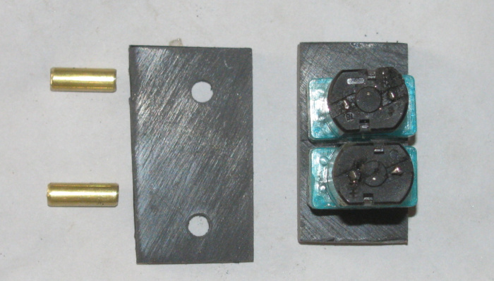
    Installed the two propeller dog bone connectors.
    Connect 2 air hoses. (inlet/outlet)

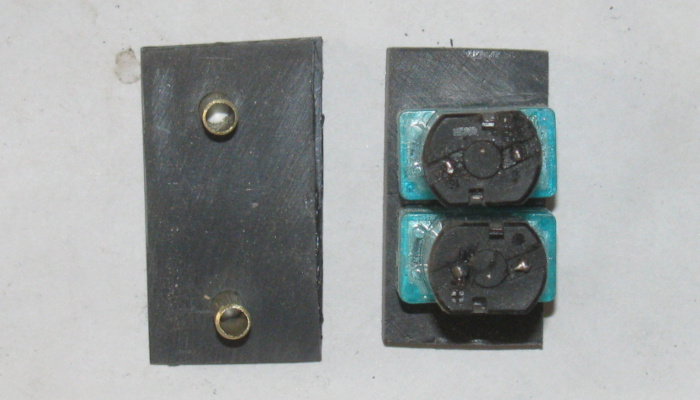
    Snap all magnetic connectors together.

    Test all controls. (Good)

    In to the test tank.
    Vent the ballast tank.
    Took about 10 seconds to fully empty the ballast tank.
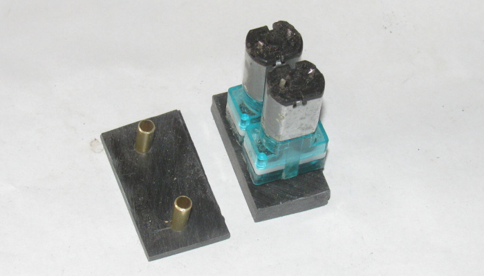
    Time to turn on the air pumps.
    Slowly turn the control knob until the first pump comes on.
    Then turn all the way for both air pumps.
    This is not exciting at all.
    I can see the boat coming up but it looks like it is going to take a long time.
    Lifted the boat out of the water.
    Removed the deck so I can see the cylinder and it's workings.

    Back in to the water.
    Fill the ballast tank by venting.
    Again 10 seconds.

    Now the air pumps.
    First pump is turned on.
    I see the air bubble coming in to the ballast tank.
    Turn on the second air pump.
    More bubbles.

    So the system works.
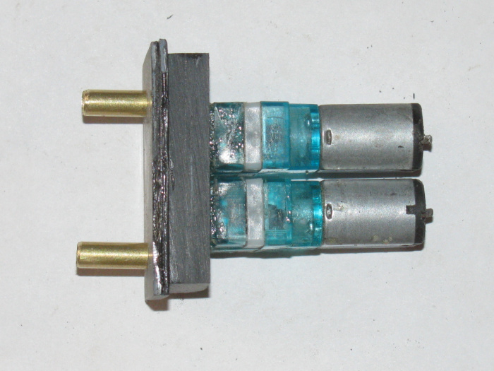
    However the air pumps are not producing the volume needed to bring the boat up.
    After 2 minutes the boat is up to about half way on the deck sides.
    This will not do.

    I check the air hoses for obstructions.
    None found.
    Just not enough volume.

    At this point I do not know if the ballast tank is large enough to bring the boat up to the waterline which was the reason for this last modification.
    Enlarged the ballast tank for more positive buoyancy.

    I have decide to shelf the Gato for now.
    I do not seem to have the correct equipment to make this work properly.
    Going to have to rethink this project.

    This system was also to see if I could use it in the George Washington.
    It does not look good.

    I have 2 working subs and a rescue barge I can run.
    So I think I will let the Gato and GW sit for a while and ask question of others at the lake on their systems.

    The problem is the small diameter of the Gato and GW cylinders.
    The pumps I have are all to big to fit.

    I am going to look in to this system.
    A video explaining the principle of a vented ballast tank. This type of diving system has been used in my VIIB. It allows for all the typical RC submarine ma...

    Comment

    • Ralph --- SSBN 598
      Junior Member
      • Oct 2012
      • 1417

      November 29th ======================

      Well as usual, I woke up with thoughts on what the problems in the Gato might be.
      I got some time late this morning so out to the shop I went.
      I removed the rear electronics tray.
      I removed the Rx, air pump section of the tray.
      Disassembled the parts from the tray to get to the pumps.
      Carefully with an Exacto knife, I slowly cut the glue holding the air pumps to the manifold.
      Cleaned the glue of the pump housings and wire brushed to get it all off.

      With the air pumps clean, I can see a possible problem.
      Each pump has a inlet and outlet for air hoses to attach.
      3 of the four had glue in the holes. (glue is an expanding glue and it appears it expanded between the air pump and manifold)
      These little air pumps are held together with a single plastic clip.
      Remove it and the pump comes apart.

      I didn't want to drill or push the glue in to the pump and damage the rubber parts.
      This way I could push or drill from the inside out keeping the dried glue out of the pump.

      At this point I have other things to do so I will test the pumps later today.

      I have a spare that I will test first to compare the other two pumps to.

      But the glue in the inlet/outlet tubes would definitely reduce the air volume.
      It looks like pump #1 was producing zero air output.
      #2 produce a restricted air output.

      If this is the case, I will build a new air pump tray section.
      I will most likely wire the two pumps together so they both come on at once.
      This will remove one switch from the system and the associated plastic mounting brackets.
      I could possibly gain another 1/2" of room in the cylinder.

      All this depends on the testing the pumps for volume in to a test cylinder I have I can change the volume to match the Gato ballast tank.
      Then I can time air filling tank.

      Comment

      • thor
        SubCommittee Member
        • Feb 2009
        • 1453

        Ralph-You are doing some great stuff! Any chance we could see a few photos of your progress?
        Regards,

        Matt

        Comment

        • Ralph --- SSBN 598
          Junior Member
          • Oct 2012
          • 1417

          There are photos in this post up to where I am.
          I am just fixing issues that keep coming up.
          --------------------------
          This mornings problems are the air pumps.
          After removing them from the tray and cleaned up I started to test them but found my test battery needed charging.
          Got that done and the other stuff not sub related.

          I have tested the air pumps.
          I started with the new pump so I would have something to use as a baseline.
          1st air pump from boat tested and work as the new pump.
          It looked to have the same volume of air coming from it.

          Moved on to the second air pump.
          This was not the same.
          It immediately pumped water out of the intake.
          That's not right.
          I hooked the hose to the intake and tried again.
          Air came out in the bowl of water.
          Had good volume.
          But this pump is using the inlet as the outlet.
          Opened it up and changed the parts around 180 degrees.
          Tested again.
          This did not go well.
          It still pumped water out the outlet and air out the inlet.

          Well now to get in to it.
          I got my 10x magnifying loop.
          Looked over the outside of the case to make sure I had the power wires on the correct terminals. (didn't matter which way they were hooked up)
          Opened up the air pump.
          Laid the parts out in order of disassembly.

          Now I took the other air pump and disassembled it.

          I could see right away that the parts where not installed the same.
          I carefully put the pump that was incorrect together the same as the good pump.
          Reassembled both.

          Tested again the good pump.
          Still good. (amazing)

          The pump that was backwards, now it pumps correctly or the same as the other 2 good pumps.

          I have all 3 pumps pumping correctly.
          Put the new pump back in the GW box of parts where it will be used.

          As far as volume of air bubbles.
          They all produce what looks to be the same volume.
          So much more than yesterdays tank test.

          I will modify the air pump tray and reinstall on the electronics tray.
          I will not use the plastic manifold but instead use rubber hose and tee fittings.
          This gets rid of about 2 oz of plastic and gains me a little more than 1/2" on the tray.

          I will use 2 switch instead of two.
          This reduces the weight even more.

          Yesterday during the tank test, during dive and surfacing, I noticed the hull rolling slightly each time as CG moved. (both directions)
          This tells me I need to look under the deck and see if I can remove more material from the support frame. (the above waterline stuff)

          I think because I changed the speed controller, this one is thinner and shorter, I may be able to change the location of the Rx.
          I may be able to stand it on end .
          I will see if this is possible.
          If so, I can shorten the tray another 3/4". (maybe)

          If that is the case, I could make the ballast tank another 3/4" longer. (not sure I need it because I have already lengthen it 1".

          Today's developments have save the boat from being shelved for the time being.

          Comment

          • Ralph --- SSBN 598
            Junior Member
            • Oct 2012
            • 1417

            December 1st ======================

            Things are going slow.
            Not much time in the shop.

            The Rear equipment tray is made in section.
            This happened when I could not get the main motor to align with the propeller shaft.
            The shaft would bind up and stop the motor.
            What I found was not what I thought.
            I thought the motor to shaft connector was off center.
            When I removed sections of the tray, the motor ran find with no binding.
            So I slowly added sections and found the problem.
            One of the servos, the rudder, would touch the cylinder as the servo moved.
            Mostly at center, the servo was touching and this pushed that section of tray down about 1/16".
            This was more than enough to bend the motor section which was part of the main tray at that time.

            I made a separate aluminum section for just the motor to connect to the end cap.
            The servo touching the cylinder wall still moved the tray but not the motor tray.
            No more motor binding.

            The tray is in 3 sections.
            Motor tray which is separate and not touching the other tray sections.
            The center section has the rudder and rear planes servos mounted and the auto pitch level controller.
            The rear section had the 2 air pumps, 2 switches, Rx, and speed controller on it.

            I have removed the 2 section that do not have the motor on it.
            The was a bend in this tray to drop the air pumps down 1/4".
            I have straightened out this tray.
            By doing this, I can make the tray 1/2" shorter.

            I am now working to make some sort of manifold for the 2 air pumps.
            I had made one before but the thing was large and heavy.
            By turning the air pumps around 180 degrees, I loose 3/8" of plastic manifold and two 3" brass tubes. (weight gone)

            The new manifold will have two 3/8" long brass tubes of which half will be in the manifold.

            I have cut out the pieces of plastic for the new manifold and bonded pieces in to 3 sections.
            I have drilled the pump pieces so the 2 pumps fit in to the 4 holes. (tight)
            A little silicone glue will hold them in place.
            I use silicone because it is easier to remove should I need to remove an air pump.

            Waiting for the plastic bond to cure.
            I will then put 2 grooves in the center section of the manifold. (air channels)

            I may gt back out to the shop for a couple of hours on Friday afternoon.

            This time of year, time gets away doing other things.

            SubRonLA has a gathering coming up in January.
            I hope to have the Gato there.

            Comment

            • scott t
              Member
              • Feb 2003
              • 879

              Matt I believe Ralph's pictures are referenced from his cliffhanger site and some users computer software filters that site out.
              I may be wrong though.

              Comment

              • Ralph --- SSBN 598
                Junior Member
                • Oct 2012
                • 1417

                Last photos I posted where in Post #101, if that helps.

                Comment

                • thor
                  SubCommittee Member
                  • Feb 2009
                  • 1453

                  Wow. Must be my browser. There are no photos showing up for me.
                  Regards,

                  Matt

                  Comment

                  • Ralph --- SSBN 598
                    Junior Member
                    • Oct 2012
                    • 1417

                    This has happened before with some members.

                    First clear your browser cache.
                    Second look through browser setting to make sure browser is not set to accelerate web pages which turns off loading images.

                    Comment

                    • redboat219
                      Member
                      • Jan 2005
                      • 519

                      Originally posted by thor View Post
                      Wow. Must be my browser. There are no photos showing up for me.
                      Same with me, no photos.
                      I'm using an android phone.

                      Comment

                      • Ralph --- SSBN 598
                        Junior Member
                        • Oct 2012
                        • 1417

                        Interesting.
                        Redboat219, you made me get my phone out and look.
                        Android phone and I See all the photos on the topics I looked at.
                        Phone is "Moto G7 Play"

                        Comment

                        • thor
                          SubCommittee Member
                          • Feb 2009
                          • 1453

                          Very strange. I viewed the post on 3 company computers and my phone (LG Android). No photos at all to view on any of them. I'm no computer whiz, but this has me baffled. I see photos on lots of other threads.
                          Regards,

                          Matt

                          Comment

                          • Ralph --- SSBN 598
                            Junior Member
                            • Oct 2012
                            • 1417

                            The complete build on my web site has all the photos and post that I copy to this forum.

                            The web page is located here:
                            http://www.cliffhangershideout.com/Gato/Gato-log-1.html

                            Comment

                            • thor
                              SubCommittee Member
                              • Feb 2009
                              • 1453

                              Thanks, Ralph!
                              Regards,

                              Matt

                              Comment

                              • Ralph --- SSBN 598
                                Junior Member
                                • Oct 2012
                                • 1417

                                December 3rd ======================

                                Assembling the air manifold.
                                Here are the two pumps.
                                The air pump mounting bracket bonded to the air channel t of the manifold.
                                The air inlet/outlet cover plate.
                                And the two brass tubes for the rubber air hoses.
                                img]http://www.cliffhangershideout.com/Gato/gato-589.jpg[/img]

                                The two air pumps on the mounting plate. (not yet glued in place)


                                The two brass inlet/outlet tubes glues in place with silicone glue. (for removal if that becomes necessary)


                                Side view.


                                Manifold with the air pumps. (not glued the cover plate needs to be trimmed to fit properly)


                                Side view.

                                ------------------------------------
                                All the plastic parts have had cement bond applied and the parts are currently in the vise and clamps to cure.
                                Last edited by Ralph --- SSBN 598; 12-03-2021, 06:29 PM.

                                Comment

                                Working...
                                X