1/144 Scale USS Batfish (SS310)

Collapse
X
 
  • Time
  • Show
Clear All
new posts
  • rdutnell
    Junior Member
    • Nov 2012
    • 388

    #271
    Re: 1/144 Scale USS Batfish (SS310)

    Good Morning Guys!

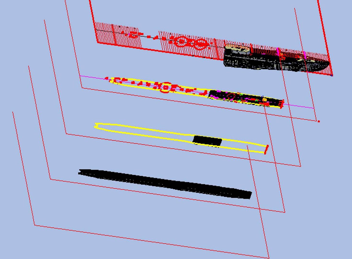
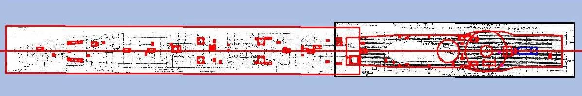
    The file size is showing the effects of the detailing Ronald. The size of the file that contains everything shown in the image below is 47.9 MB. It includes four hull parts, the anchor, the forward diving plane parts (4), the hydrophone and the fairweather, my deck templates, and all of my miscellaneous construction lines and grid lines.


    I made some more progress on it last night, but not much. I will post it later, but first I have a question about the 10 pound blow valves. The only thing I have been able to find so far is from The Fleet Type Submarine Online site. Below are two pictures I copied from it.


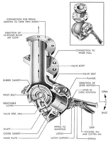
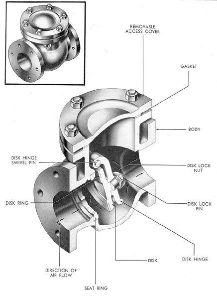
    My question is, “What did it look like at the deck?” I haven’t been able to find a picture of one. Would it have been just a flange and a hole?
    Any help would be mucho appreciated.

    Comment

    • scott t
      Member
      • Feb 2003
      • 880

      #272
      Re: 1/144 Scale USS Batfish (SS310)

      Looks like this valve is bolted in the crew spaces of the submarine.
      Notice the picture has a flange that says " Connection to Inner Hull".
      Where on the boat do you think it is located?

      Comment

      • rdutnell
        Junior Member
        • Nov 2012
        • 388

        #273
        Re: 1/144 Scale USS Batfish (SS310)

        UPDATE 106

        Hi Guys!

        It isn’t an “it” Scott, it’s a “they”, and there are 9 of them. According to the Fleet Type Submarine Online site they are located as follows][/url]


        I then copied them all to the model and the deck working area, I guess you could call it, copied Part 4 to the drawing, and sliced the deck section to match it.


        Here’s a close up of the Part 4 deck with the tracings positioned on it. The round circle is the location of the forward edge of the fairweather.


        As before the tracings for the AS’s had to be resized and moved slightly due to the off scale battens I had to use. In the image below the red line is the outline traced from the plans and the magenta line is the resized and positioned version.


        I had to do the same for the blow valves.


        The image below shows the deck with the modified features.


        These new outlines were extruded through the deck…


        …And subtracted.


        At this point I moved the deck over the model, but as before the deck at thispoint on the ship is not flat, it is sloped, as seen in the image below.


        So I rotated it and as before, l copied it down in stages subtracting as I went, until it was in position.


        The end didn’t quite get cut off on the aft end, so I drew a polyline…


        …Extruded it…


        …And subtracted it.


        Next I copied the fairwater to the drawing…


        …And subtracted it. For some reason AutoCad wouldn’t let me subtract it any lower than 0.01” above where it is supposed to be. I have no reason why, so I guess I will have to live with it.


        With the deck complete and in position, I joined it to the rest of the model and prepared to add the AS’s.


        To assure proper alignment, I used the clipboard to copy them to the various locations and then joining and subtracting t he various parts as before.


        At this point I stopped because I don’t know what the blow valves look like. I will complete the part when I do.

        CHEERS!!!

        Comment

        • rdutnell
          Junior Member
          • Nov 2012
          • 388

          #274
          Re: 1/144 Scale USS Batfish (SS310)

          UPDATE 107

          Hi again guys!

          This isn’t so much as an update as a presentation of options for the 10 pound blow valves. I see two options, although there may be more. The image below shows one of the blow valves with construction lines in magenta.


          The following images show the process for the first option with the first two images showing the extrusions used to make it, first in Conceptual Visual Style…


          …Then in wireframe to better see the extrusions.


          In the first option, the extruded rectangle is first subtracted from the deck…


          …Then the inner extruded circle is subtracted from the outer one. The resulting tube would be attached to the deck.


          The setup for the second option is shown in the image below. The extruded rectangle (red) wouldn’t be needed because the base would already be there. However, since I just subtracted it for Option 1, I had to re-extrude it. For the second option the circles were moved 0.005” above the platform then extruded.


          At this point the outer circle would be joined to the deck and the inner circle subtracted from it.


          The second option would be the easier of the two, and is the way I am leaning, but I thought I would bounce it off you guys before I actually do it. What do you think? Option 1 or Option 2? Perhaps Option 2 with the flange level with the deck instead of raised 0.005”? Or something else?

          CHEERS!!!

          Comment

          • tom dougherty
            Senior Member
            • Jul 2005
            • 1361

            #275
            Re: 1/144 Scale USS Batfish (SS310)

            We need Bill Lambing in on this one for sure... But, I think the ballast tank riser openings may not vent through the superstructure deck atop the pressure hull itself but actually through the ballast tank sides along the hull.

            I think what I have indicated below (red arrows) may be the riser openings (blanked off with a cover plate) on Lionfish][/url]


            If you examine the deck visible in this photo, I see no openings similar to the ones you created in the superstructure deck][/url]

            Comment

            • wlambing
              SubCommittee Member
              • Feb 2003
              • 848

              #276
              Re: 1/144 Scale USS Batfish (SS310)

              Gents,

              Hi, Tom!
              The features Tom has highlighted are manway covers for access in fuel ballast tanks. The 10-lb. blow valves only are used in MBT group two and six tanks for list control and are operated from topside, on the main deck. Chapters 5 and 10 in The Fleet Submarine textbook in the HNSA website describes and illustrates the MBT and Salvage Air systems. The actual MBT vent risers terminate under the superstructure and can't be seen from outside or above. I'm not really sure what the 10# gate valve operators look like from the main deck. This will take a bit of research on plans or in more pictures.
              I would think that the deck wrench used to operate the 10# valves would fit into a socket similar in size to that where the ASS (Air, Ship Salvage on Nucs!) connection valve stem is. The textbook does tell us that there is an ID plate surrounding it and the plate has ID lugs to let a diver know where he is. There is no exposed handwheel there. Looking at rd's rendering, the size for the circular plate looks about right!

              Have fun with this, I'm going deep for a month!

              Bill

              Comment

              • scott t
                Member
                • Feb 2003
                • 880

                #277
                Re: 1/144 Scale USS Batfish (SS310)

                The valve you are looking at is to add air to the ballast tanks after surfacing.
                It dumps low pressure air into the ballast tank .

                What I think you want are the vents that let the air escape. On modern
                submarines they are flush with the deck surface.

                Looking at the digram the vents are below the deck.


                Shows vent valves.


                Comment

                • wlambing
                  SubCommittee Member
                  • Feb 2003
                  • 848

                  #278
                  Re: 1/144 Scale USS Batfish (SS310)

                  Thanks, Scott!!

                  I'm too 'puter illiterate to get the illustrations and then post them. Good choice of explanatory pics, too!

                  B^)

                  Comment

                  • scott t
                    Member
                    • Feb 2003
                    • 880

                    #279
                    Re: 1/144 Scale USS Batfish (SS310)

                    Thank you Bill. Your explanation kept me from posting stuff I am just making educated
                    guesses at. While you posted I was looking for pictures. Then when I posted I read what
                    you had stated and quickly edited my post so I didn't look ignorant.

                    So the 10lb valves where probably operated through a hole in the deck with that water-valve-key like wrench.
                    And it probably had a nameplate with a hole through it to designate which tank it was on.

                    If you want to add the pictures:
                    open new tab and navigate to picture
                    right click on picture and pick properties
                    pick on the address and type ctrl+A to select the whole address
                    type ctrl+C to copy
                    close that window
                    select the subcommittee tab and post a reply
                    select Img button and you should see [ /img]
                    type ctrl+V to paste the content you copied
                    That should add the picture you want

                    The trick is having both the Subcommittee open and the location of the picture open on different tabs.

                    Scott T

                    Comment

                    • rdutnell
                      Junior Member
                      • Nov 2012
                      • 388

                      #280
                      Re: 1/144 Scale USS Batfish (SS310)

                      Man! You guys are all over it. Thanks Tons!

                      As so often happens, as one question is answered, new ones emerge. In this case the water is still pretty muddy for me.
                      Some of the problem comes from the timing/ship thing because they are all so different. They started with multiple plan sets and many mod’s were made on the fly so I’m starting to wonder if it is even possible to model one 100% accurately.

                      The plans I have for the wood deck are Portsmouth No 151-393, superseding “Plan No. 151-381 for SS 393 to 434 incl.” It was superseded by two different sets of plans applying to some of the ships, such that it appears that the plans apply only to SS 393, 394 and 411.
                      The “Superstructure Sides & Main Deck –Frames 66 to 125 Incl” plans (Portsmouth No. 136-381) appears to have originally been for “SS 381 to 434 incl.”, but supersedings make them applicable only to “SS381 to 397 incl.” So, the only two ships that both sets of plans are applicable to are Queenfish (SS 393) and Razorback (SS 394).

                      Compare the picture in Tom’s last post of Lionfish’s (SS 298) deck with the picture below of Capitaine (SS 336)cfrom Navsource. Lionfish doesn’t have a wood deck and I don’t see the AS’s much less the stop valve fittings. Capitaine seems to more closely match the plans. Numerous AS’s are visible around the deck, and it is possible that a stop valve fitting is shown between the 2 guys on the right, although I can’t tell. Comparing this deck with the plans was fruitless. A couple of hatches seem to be similar to the plans but the AS’s are definitely located differently.

                      This can get ridiculous in a hurry. I mean, in the picture below you can see portions of four submarines. They all appear to be different and you can only see a small portion of them.


                      It’s 3rd and a mile over here. The punter is warming up his leg. I’m thinking about changing the name of my model and just going for it. Perhaps I could name it the USS Walrus, USS Nerka, USS Copperfish, USS Starfish or some other fictional name. Or I could make up my own name, say the USS Alligator Gar or USS Leopard Darter. I’m only kidding of course, but I think I could spend a year researching it and still not be certain that it was correct, no matter what time period I wanted to model. Of course I have pictures of the way she is now, but I’m pretty sure that when they redid the deck they left out a lot of things as few hatches remain and there are no AS’s. So, I don’t really want to model her in her current configuration, which results in a flag for delay of game. Now it’s 3rd and a mile and 5 yards.

                      I just read Scott’s last post as I was writing this, and based on that, if I want to include the stop valve fittings, it is simply a matter of drilling a hole in the plates, like Option 2 in my last post. Decisions. Decisions.

                      On another note, taking a break from Batfish until I decide how to deal with the deck, last night I did a little CAD work to make some money to get the models I’m making printed. I have been asked by an individual (who will remain anonymous to protect the innocent) to make some 1/700 scale 1950s navy aircraft for a 1957-8 USS Midway build he is making. I know it is way off topic and doesn’t have anything to do with submarines, but it is naval, and the way I am going to make the proceeds to pay to get my Batfish model printed. Plus, I thought you may be interested, so here’s the scoop.

                      I was sent the plans shown below for the Douglas AD-5 (A-1E) Skyraider on Monday.


                      When I first saw them, I didn’t think I could do it, or that it would take a long, long time. I spent about an hour messing with it at the first of the week, but gave it up as too difficult. Yesterday afternoon however, it popped into my head how to go about it, and early this morning after about 8 hours of work I completed the first draft. Here are some images of it, including 4 from AutoCad…


                      …And 2 from SolidView.


                      I think I will take one more day, or at least part of it, and make the AD-5W that he also wants. It should be an easy modification to make.

                      CHEERS!

                      Comment

                      • tom dougherty
                        Senior Member
                        • Jul 2005
                        • 1361

                        #281
                        Re: 1/144 Scale USS Batfish (SS310)

                        They all appear to be different and you can only see a small portion of them.
                        Welcome to the always confusing world of Fleet Submarines! Yes, some were built with complete teak wood decks, and some had partial teak wood and then metal deckplates. As time went on, much of the deck was metal plate, particularly in post war boats that were heavily used.
                        That is the case with Lionfish][/url]


                        Comment

                        • rdutnell
                          Junior Member
                          • Nov 2012
                          • 388

                          #282
                          Re: 1/144 Scale USS Batfish (SS310)

                          Great stuff as always Tom D! Confusing to be sure and frustrating to boot.

                          If I am not mistaken (which is highly possible) the last image in your last post answers my initial question about the blow valve deck fittings as I think one is shown right next to the AS in the lower middle of the picture. The only difference is that the base plate is round rather than square.

                          In any case, think I have about decided to forego accuracy on the deck and follow the plans I have. Not many will notice, and some of it will be right. I just don’t see any other options unless plans for Batfish herself were to fall in my lap, and I don’t see that happening.

                          Comment

                          • scott t
                            Member
                            • Feb 2003
                            • 880

                            #283
                            Re: 1/144 Scale USS Batfish (SS310)

                            Submarine museums.org http://www.submarinemuseums.org/foru...?topic=190.270
                            Some pictures of the deck replacement on Batfish. I did not see 10lb valves but you can see what I think are
                            the main ballast tank valves. One has a rectangular shape on top and the others you can see springs by. You
                            can read twenty pages about the deck replacement with some pictures also.


                            Comment

                            • rdutnell
                              Junior Member
                              • Nov 2012
                              • 388

                              #284
                              Re: 1/144 Scale USS Batfish (SS310)

                              UPDATE 108

                              Hi Guys!

                              Great pix Scott! I joined Submarine museums.org after you mentioned them in an earlier post and have had some feedback from them. I hadn’t taken the time to go through past posts though, until your post here. When I did, I found this picture that I am pretty sure shows a 10# stop valve. It is the object in the second opening up and to the right of the SA. At least the plans show one here and it looks right to me. The square dark object is the plate that would be seen on the deck. It even looks a lot like the plate on the SA, but smaller, as it should be. The lighter portion would be below the deck.


                              I now know how I am going to do them, but first I did some modifications to both the deck on “Part04-Hull04” and to “Part11-Fairwater”. Starting on the deck I trimmed some tin sections of battens along the sides because they would be way too thin to print. The image below shows the extruded rectangle I subtracted to remove them.


                              Here it is after it was subtracted.


                              Next I removed the battens on the inside of the fairweather. I had to do this in stages, and I started in the middle first drawing a rectangle where I needed it.


                              Then extruding it…


                              …And subtracting it.


                              The next few images show the process repeated to remove all of the interior battens.


                              At this point I decided that I needed to cut the points off of the battens around the fairwater, because they too are too pointy to print. Besides that is the way they are cut on the real ship. To do this I drew a rectangle to encapsulate one batten, and copied it to the correct locations on the other battens. I started with the starboard side on the aft end.


                              These rectangles were extruded forward and subtracted.


                              I did the port side the same way.


                              I did the aft end all at once.


                              I think it looks a lot better, and I know it will print better.


                              Next, I turned my attention to the ventilation induction line that was left high and dry by the deck mod. I started by aligning my coordinate system with the flange, drew a circle and extruded it.


                              I then sliced it at the bottom of the battens…


                              …And subtracted it from the deck.


                              Next I removed the battens between the pipe and the bulkhead in the same fashion that I removed the battens in the fairwater space.


                              This really left the pipe high and dry.


                              I re-extruded the pipe circle…


                              …And again sliced it off at the bottom of the battens.


                              At this point I considered making the ventilation induction line a separate piece, but instead decided to keep it part of the fairwater, but provided some support for the bottom of the pipe. I did this with a rectangle the same size as the area between the uncut battens, extruded down from the bottom of the pipe. This extruded rectangle was added to the bottom of the pipe…


                              …And subtracted from the deck.


                              In the following image, I colored the fairwater yellow so the match could be seen. Note that the extension should slide right in place so that the top of it will be right at the level of the bottom of the battens.


                              CHEERS!!!

                              Comment

                              • rdutnell
                                Junior Member
                                • Nov 2012
                                • 388

                                #285
                                Re: 1/144 Scale USS Batfish (SS310)

                                UPDATE 109

                                Hi again guys!

                                This is a short and sweet update as I just decided how to do the 10# stop valves, and not only were they easy to make, but there are only four of them on the Part 4 deck. The image below shows the design I settled on. It is the rectangle outline I defined earlier, extruded 0.004”. The diameter of the circle is from the plans and it is extruded to the bottom of the battens.


                                The process is to join the plate to the deck, then subtract the extruded circle. The following images show it on the part.


                                This last image shows what I think is the stop valve and AS (middle one) seen in the picture in my last post.


                                CHEERS!!!

                                Comment

                                Working...