
Hello Everyone! My name is Russ.
Welcome to the start of this build log of the USS Batfish (SS310) in 1/144 Scale. Unlike many models on this forum, it is not being built for RC. It is simply going to be a static display model. I considered not posting the log because I have no idea how long it will take to complete, or if I will ever complete it, but I decided that doing so would give me incentive to document the build process from start to finish, whenever that may be.
Why the Batfish?
Well, I have recently become interested in using AutoCad to make 3-D models. My first attempt at it was a 1/144 scale USS Greenling (SSN-614), a Permit class submarine that a friend of mine was on in the early 70’s. The first draft was recently “printed†on an SLA 3D printer, and I only received it this week. I haven’t started building it yet because I am not sure exactly what I am going to do. The picture below shows the parts in the first draft print. You may notice that a rudder is missing, that is because the guy that made them inadvertently forgot it. He is making (or has already made) another one, along with a couple of spare screws, but I don’t have them yet.
A second draft, with much greater surface detail, has been designed and hopefully will be built in the near future. If you are interested, the compete build log for Greenling is available at]viewtopic.php?f=35&t=11272[/url]
In the meantime, I got interested in Batfish strictly because of geography. She is located in Muskogee at the “Muskogee War Memorial†(http://www.ussbatfish.com/) and I am in that area quite often. When I first found their website, I was intrigued by the shape and thought that it would provide a greater challenge than the circular hull of Greenling.
The weekend before last I had to go to Tahlequah and, on the way home, I stopped by the museum. I arrived right at closing time, and didn’t want to be rushed on the tour, so I didn’t get aboard her. I did pick up a brochure and had a good talk with the curator, who informed me that although they did not have plans for Batfish, plans for USS Pampanito (SS-383), another Balao class submarine, were available on-line. When I returned home, I quickly found the site and the plans (http://www.maritime.org/tech/drawings/index.htm).
When I discovered the plans, I decided to try to build her.
The “build†will really consist of two builds, a “virtual build†using the plans and AutoCad to design a 3D model and create the STL files for printing on a 3D printer, and a “real build†when the model will be physically built. The beginning of the virtual build process is described below, and will continue in successive posts until the design is completed and ready to be printed. Descriptions of the real build will follow.
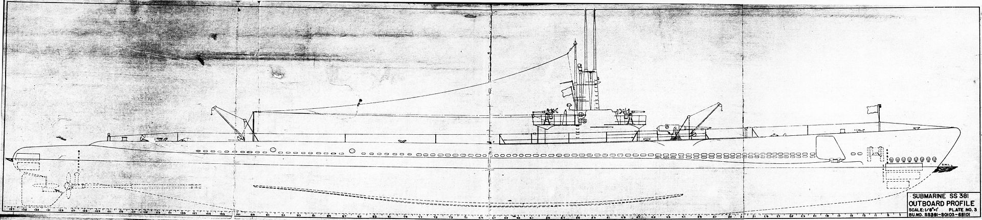
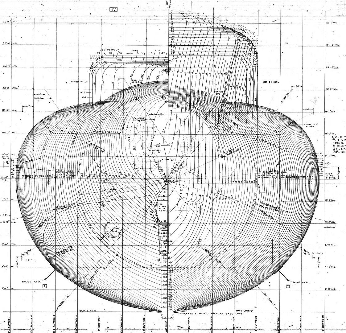
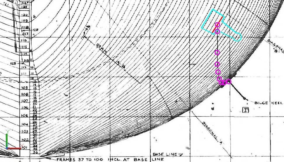
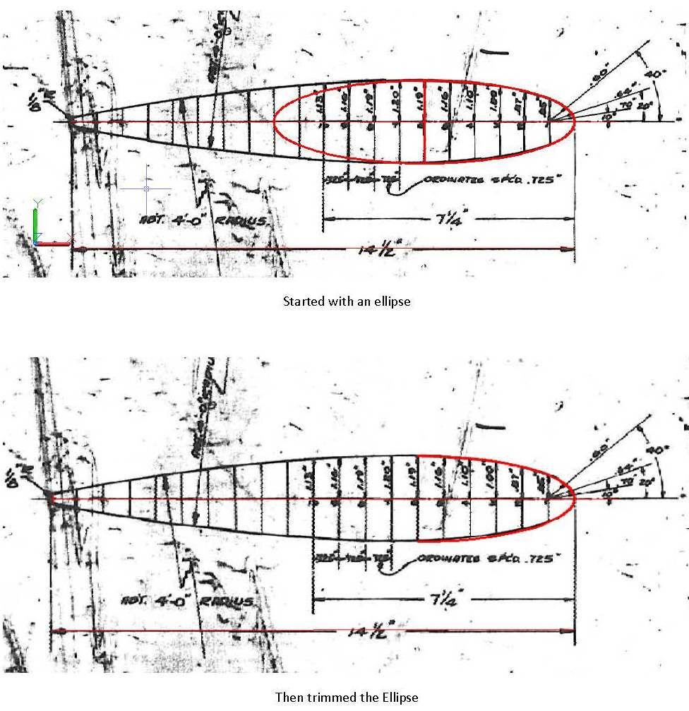
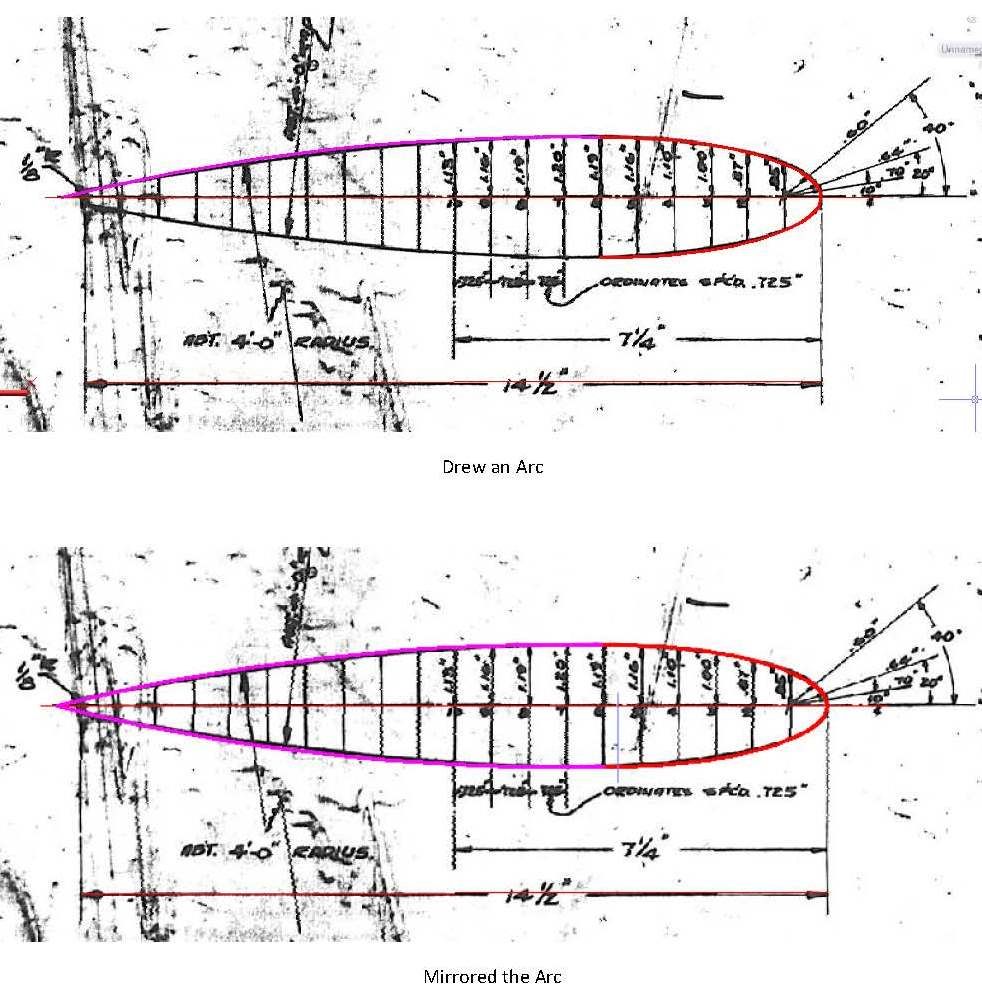
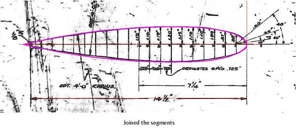
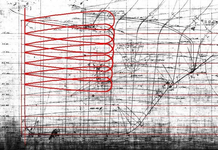
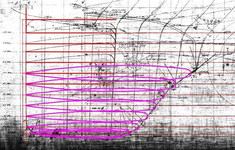
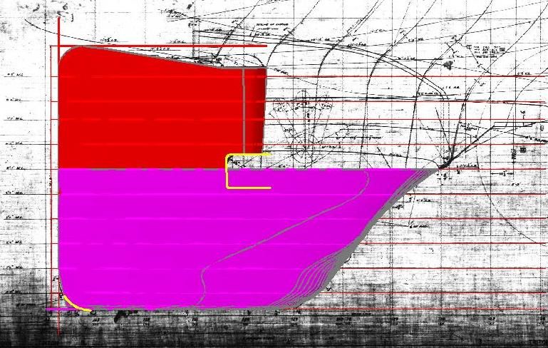
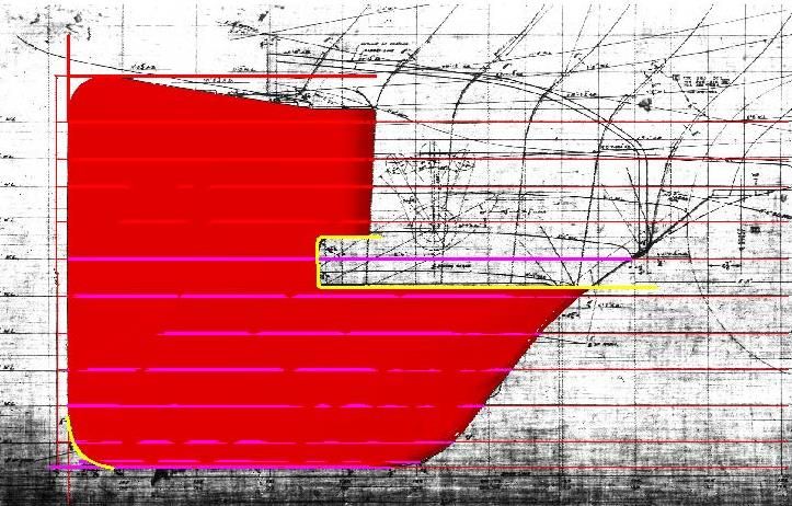
I began the design by importing some of the plan drawings available on the Pampanito site into AutoCad and scaling them to the proper size. I started with the “Body Plan – Outer Hull†plan sheet, and using polylines I traced the hull half-sections (or Frames) from the plans. I then mirrored and joined the polylines to form the various sections. The image below shows the stern and bow sections created in this process.
Each Frame is numbered and the spacing of the frames is provided on both the “Body Plan – Outer Hull†and “Outboard Profile-Plate No. 3â€plan sheets. Using the base line, I copied the Frames to their respective locations on the profile, rotated them 90o, and then lofted them. The hole in the forward edge of the bow was adlibbed, as I didn’t find any plans for it.
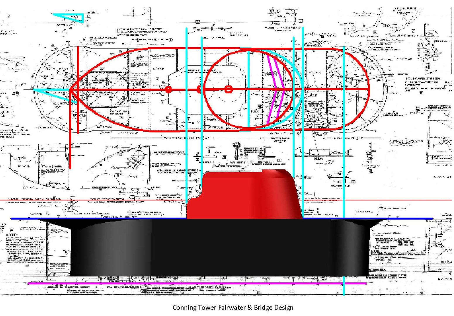
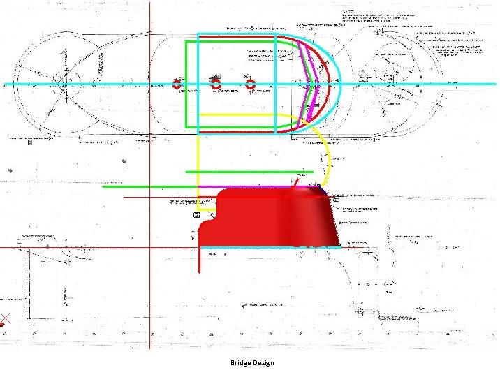
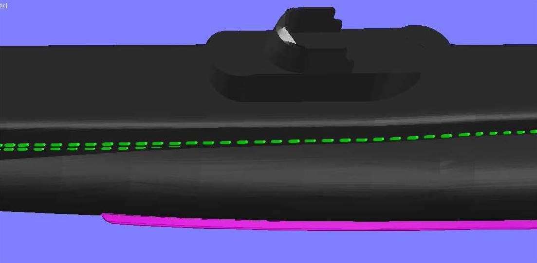
The Conning Tower was made using the “Conning Tower Fairwater & Bridge, Elevations & Plans†sheet. The bridge was made using a combination of this sheet and the “Conning Tower Fairwater & Bridge – Molded Lines & Offsets†plan sheet. The completed assembly was then copied to the correct location on the hull.
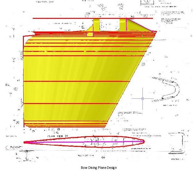
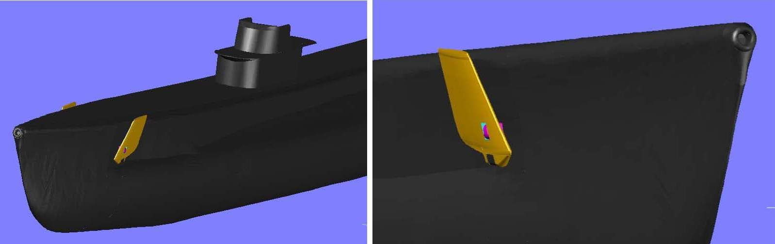
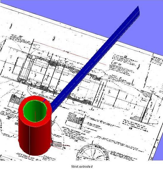
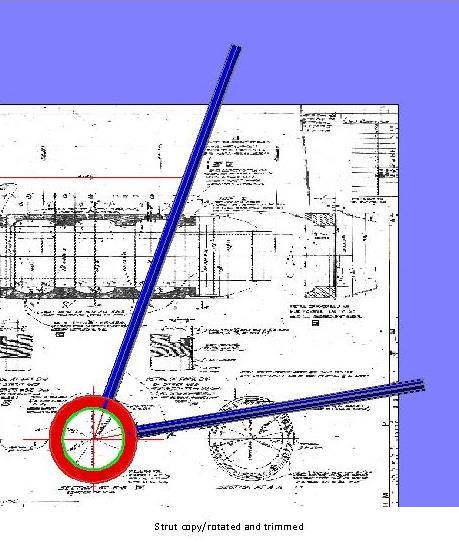
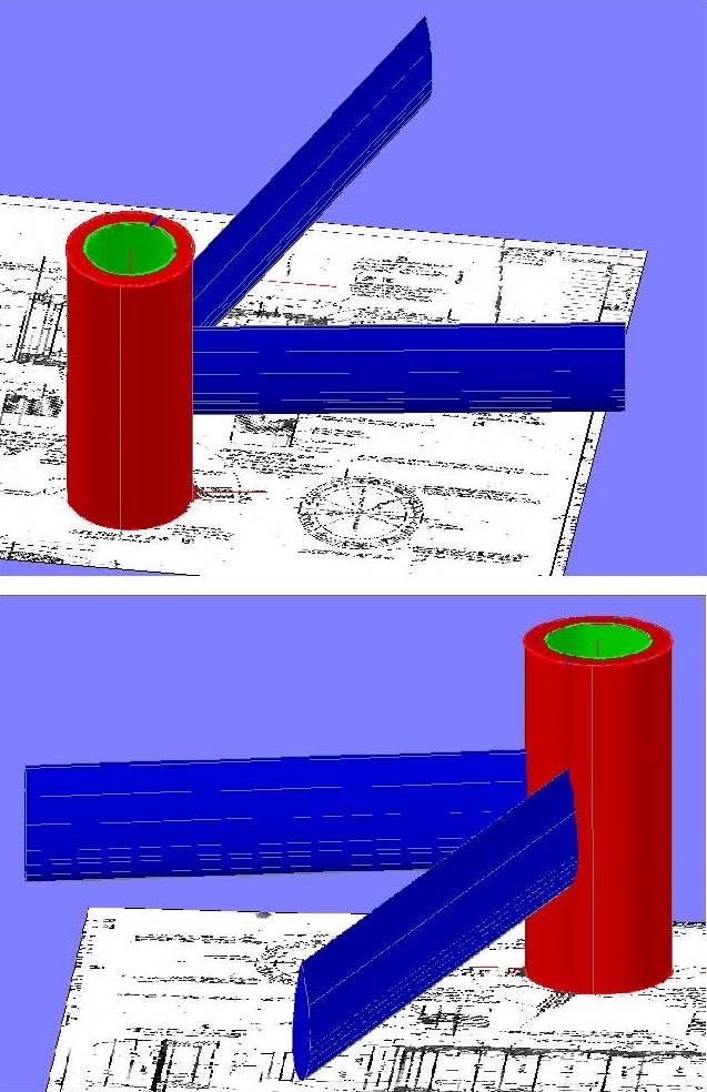
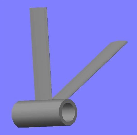
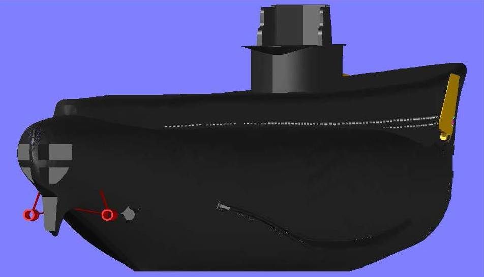
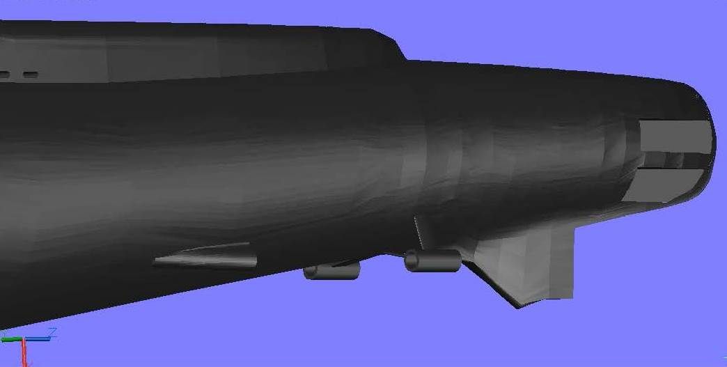
The next items to be completed were the bow planes, which were created using the “Bow Diving Gear Plane Details†sheet and pictures of Batfish. The pictures were required because the configuration in the pictures I have of Batfish is slightly different than the configuration on the plans.
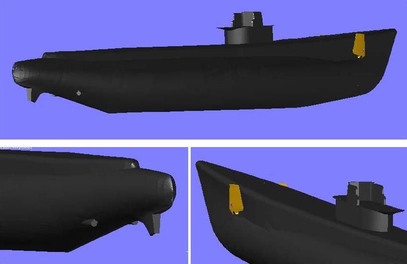
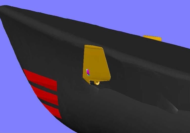
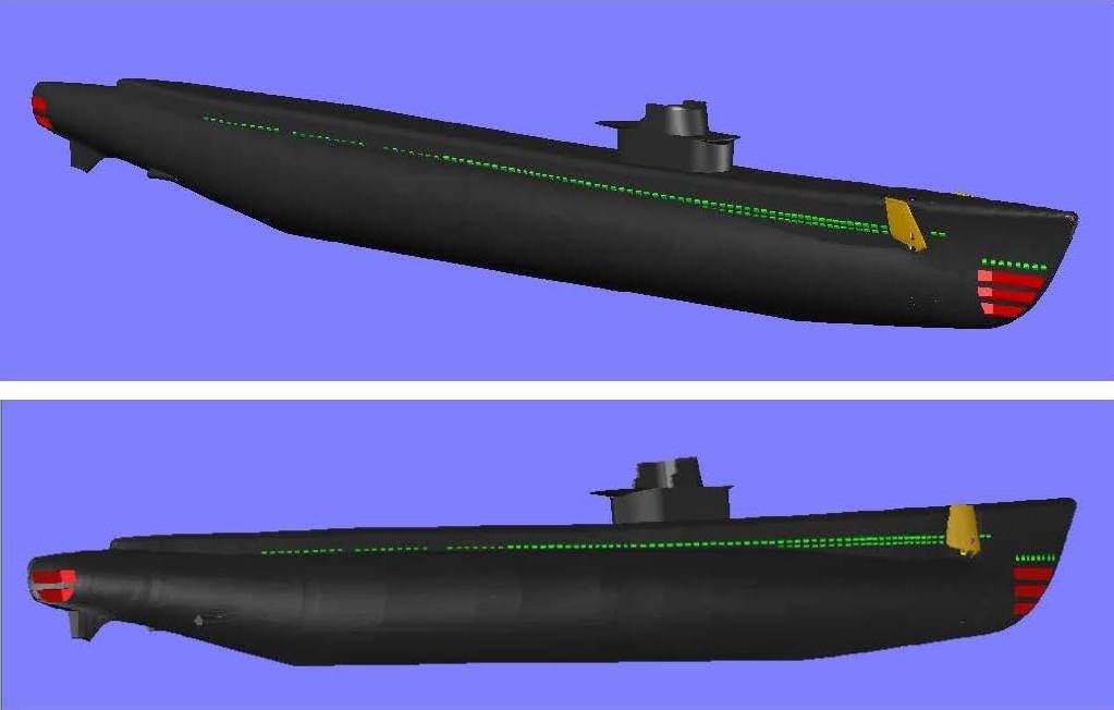
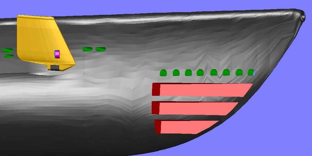
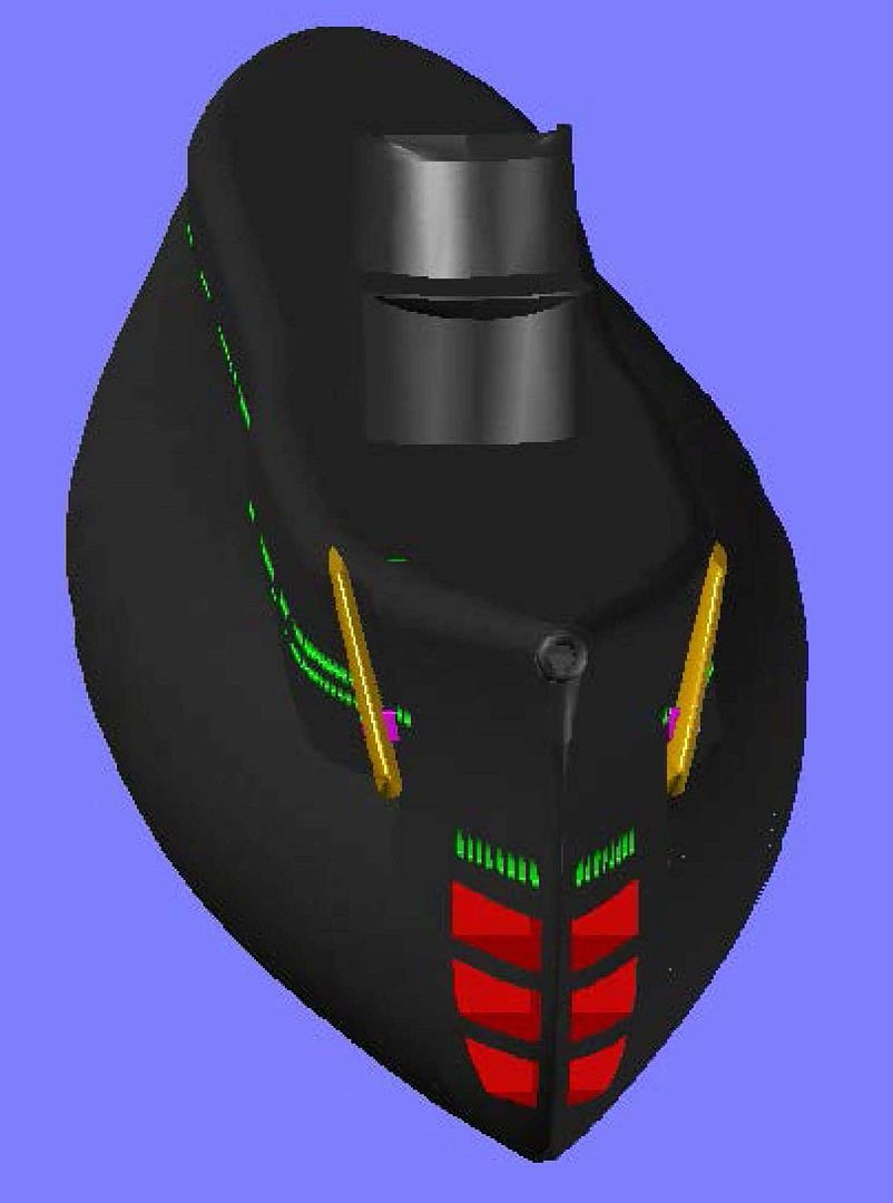
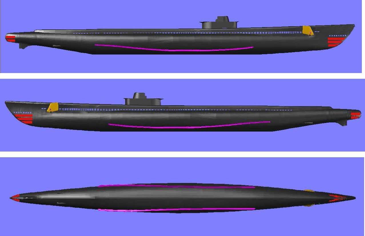
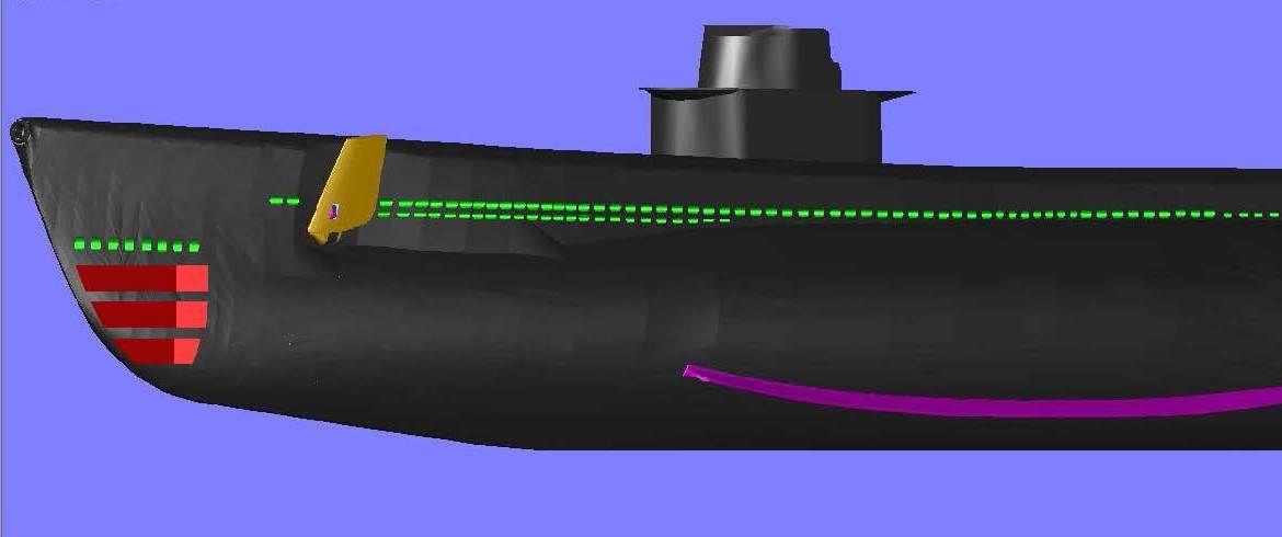
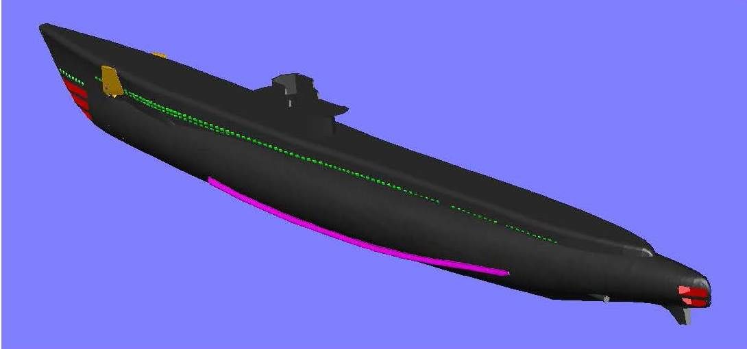
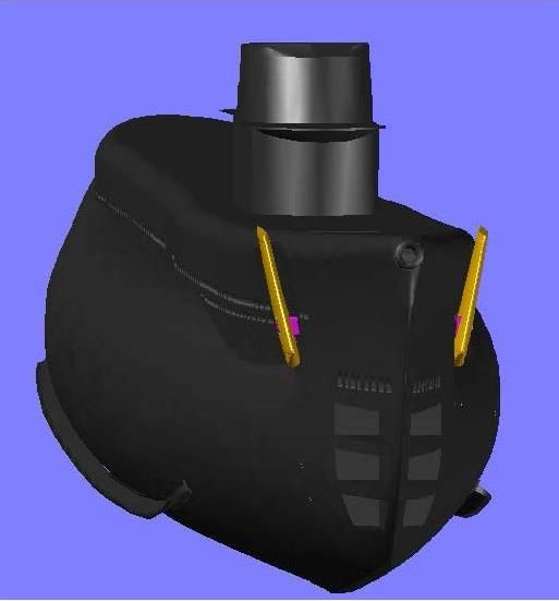
Below are some images of the ship up to this point. The bow plane is a separate piece and thus is colored orange. Also, I am uncertain about the upper hull attachment point, so at present it is still detached and colored magenta.

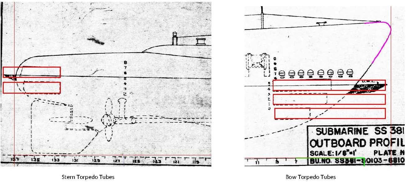
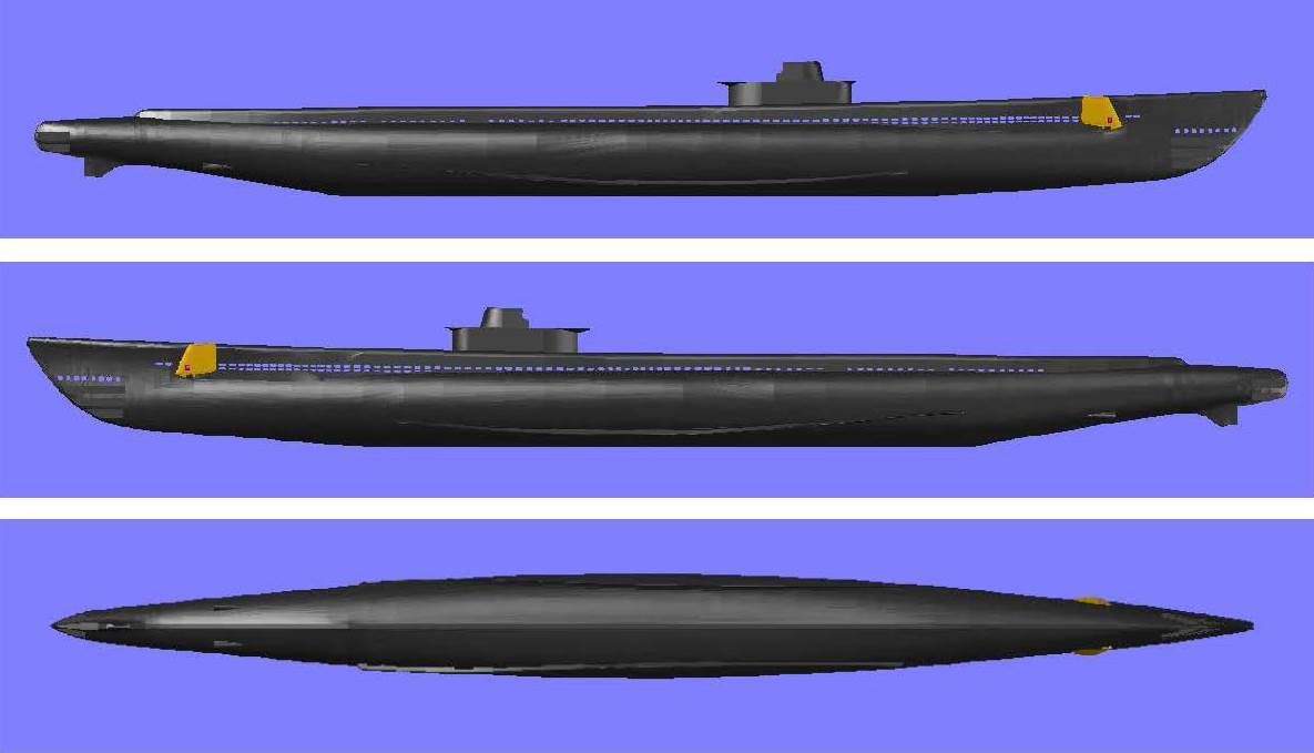
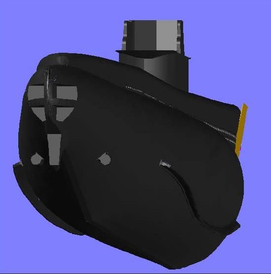
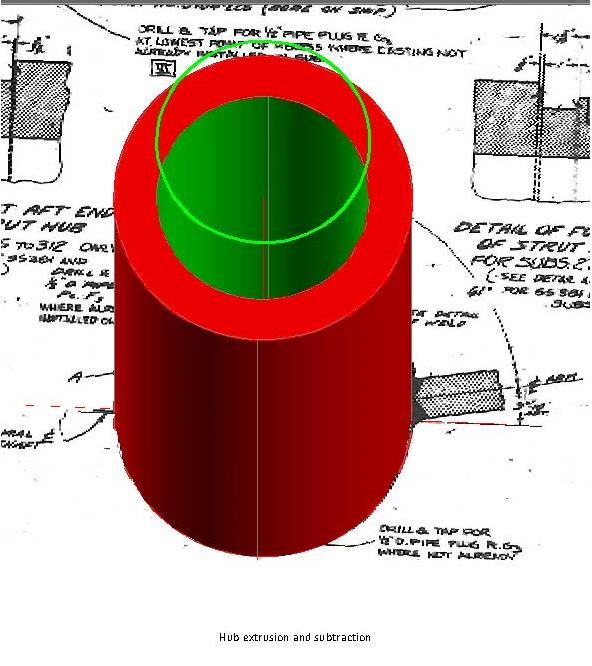
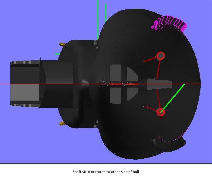
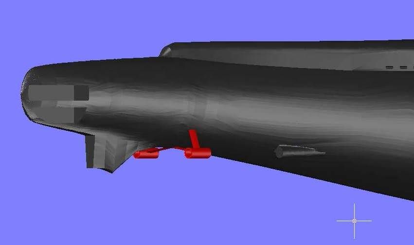
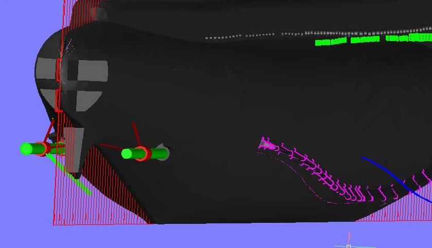
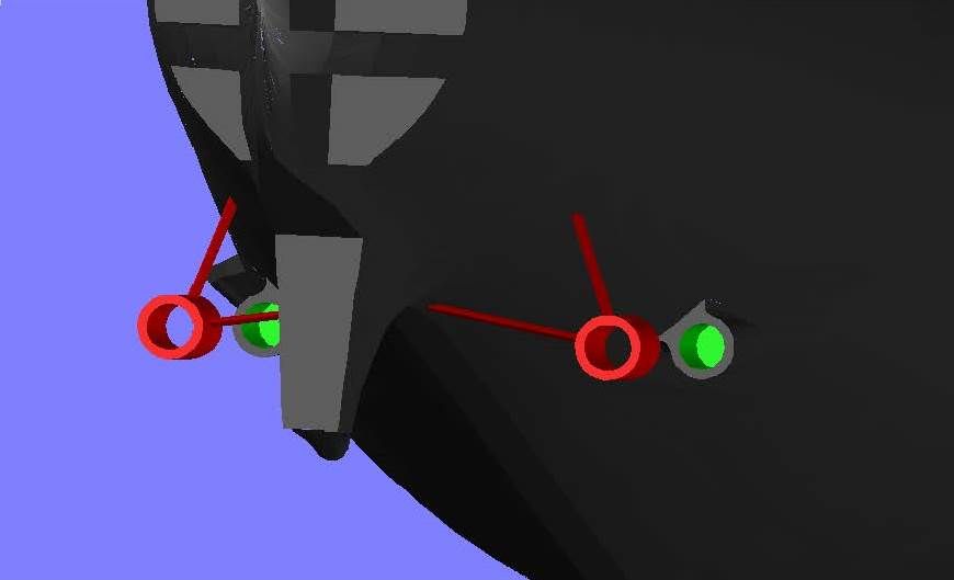
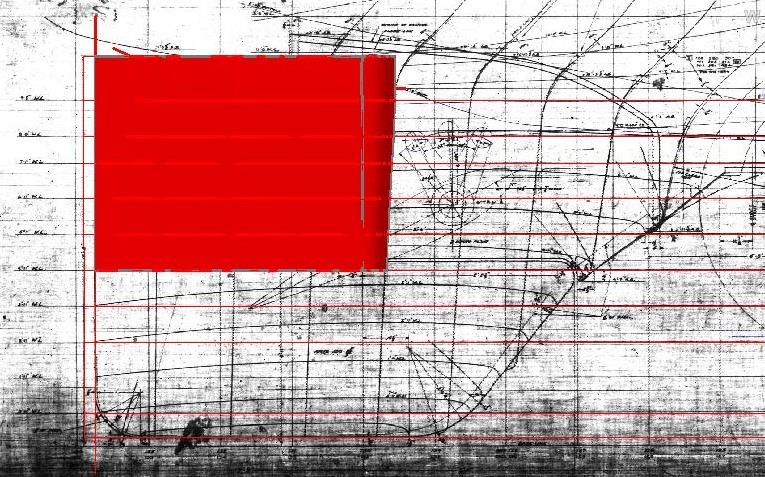
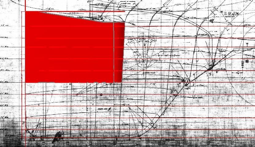
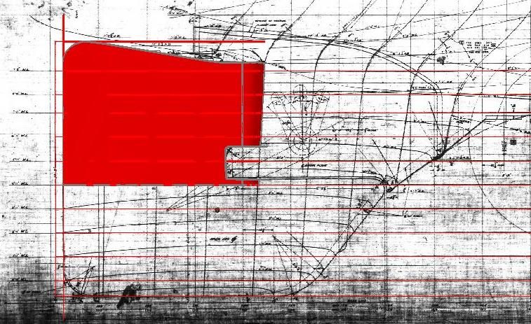
The next thing I did was cut out the torpedo tubes. I did this by first tracing the outlines from the plans, extending them well past the outline of the ship.
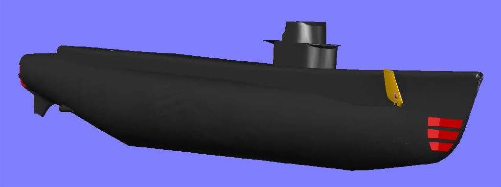
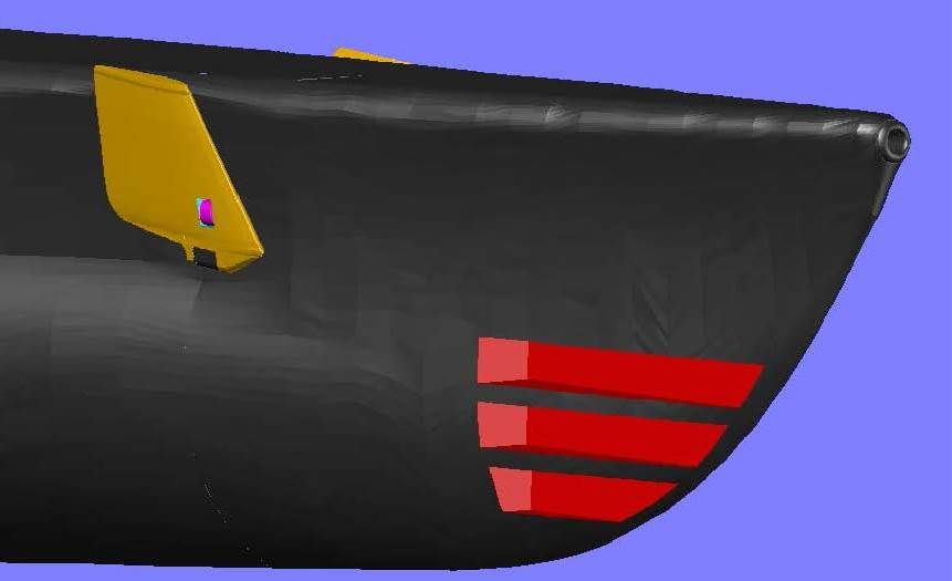
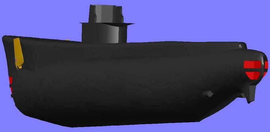
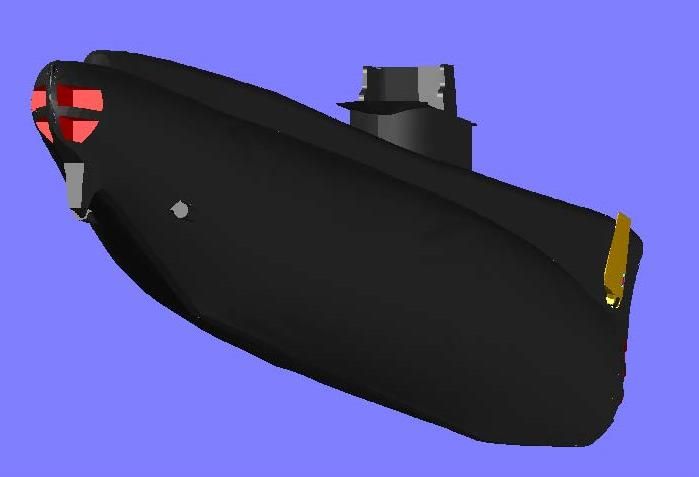
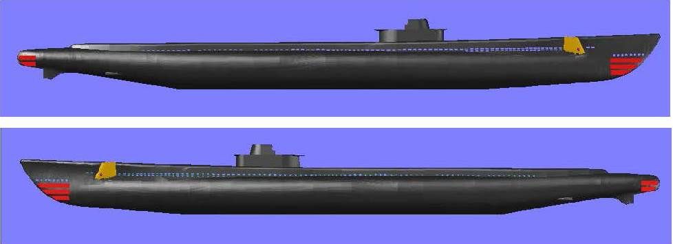
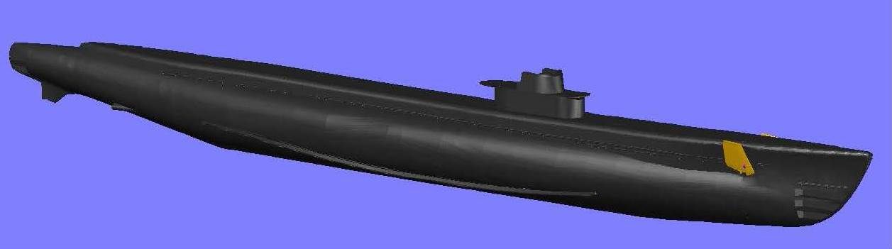
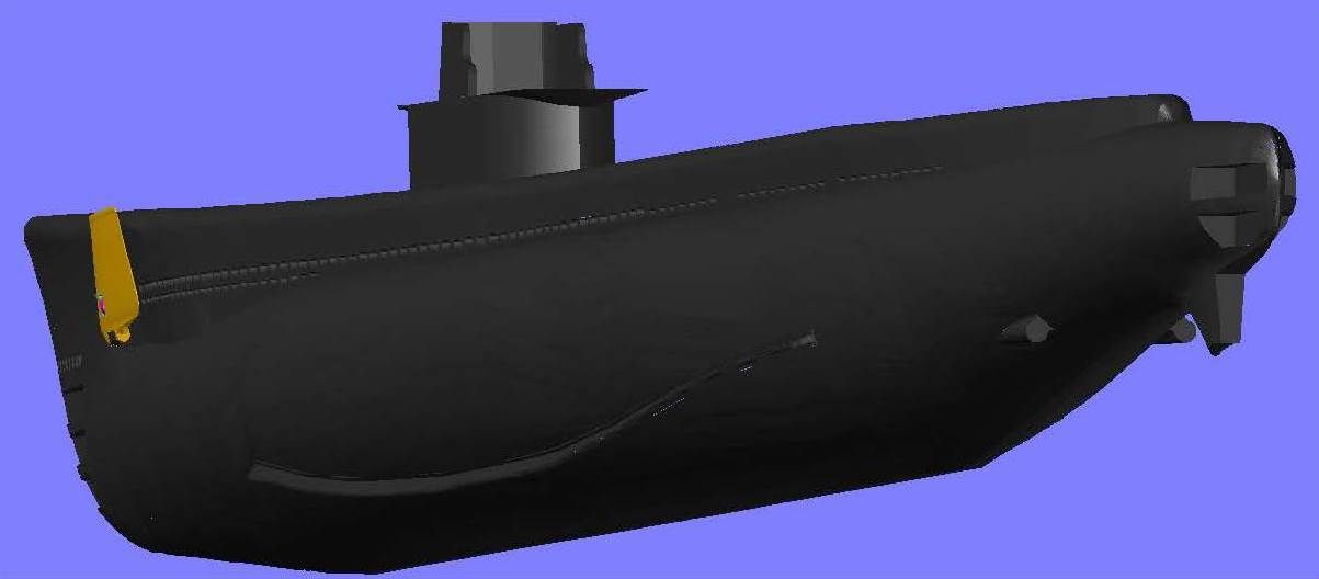
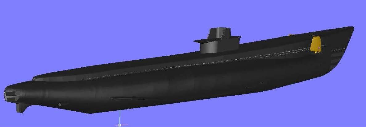
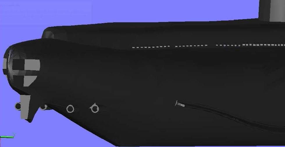
These rectangles were copied to the correct locations on the 3D hull, lofted and then subtracted. The remaining images on this post show the Batfish model as she currently stands.
I will post more as I get it done.
CHEERS!!!
Welcome to the start of this build log of the USS Batfish (SS310) in 1/144 Scale. Unlike many models on this forum, it is not being built for RC. It is simply going to be a static display model. I considered not posting the log because I have no idea how long it will take to complete, or if I will ever complete it, but I decided that doing so would give me incentive to document the build process from start to finish, whenever that may be.
Why the Batfish?
Well, I have recently become interested in using AutoCad to make 3-D models. My first attempt at it was a 1/144 scale USS Greenling (SSN-614), a Permit class submarine that a friend of mine was on in the early 70’s. The first draft was recently “printed†on an SLA 3D printer, and I only received it this week. I haven’t started building it yet because I am not sure exactly what I am going to do. The picture below shows the parts in the first draft print. You may notice that a rudder is missing, that is because the guy that made them inadvertently forgot it. He is making (or has already made) another one, along with a couple of spare screws, but I don’t have them yet.
A second draft, with much greater surface detail, has been designed and hopefully will be built in the near future. If you are interested, the compete build log for Greenling is available at]viewtopic.php?f=35&t=11272[/url]
In the meantime, I got interested in Batfish strictly because of geography. She is located in Muskogee at the “Muskogee War Memorial†(http://www.ussbatfish.com/) and I am in that area quite often. When I first found their website, I was intrigued by the shape and thought that it would provide a greater challenge than the circular hull of Greenling.
The weekend before last I had to go to Tahlequah and, on the way home, I stopped by the museum. I arrived right at closing time, and didn’t want to be rushed on the tour, so I didn’t get aboard her. I did pick up a brochure and had a good talk with the curator, who informed me that although they did not have plans for Batfish, plans for USS Pampanito (SS-383), another Balao class submarine, were available on-line. When I returned home, I quickly found the site and the plans (http://www.maritime.org/tech/drawings/index.htm).
When I discovered the plans, I decided to try to build her.
The “build†will really consist of two builds, a “virtual build†using the plans and AutoCad to design a 3D model and create the STL files for printing on a 3D printer, and a “real build†when the model will be physically built. The beginning of the virtual build process is described below, and will continue in successive posts until the design is completed and ready to be printed. Descriptions of the real build will follow.
I began the design by importing some of the plan drawings available on the Pampanito site into AutoCad and scaling them to the proper size. I started with the “Body Plan – Outer Hull†plan sheet, and using polylines I traced the hull half-sections (or Frames) from the plans. I then mirrored and joined the polylines to form the various sections. The image below shows the stern and bow sections created in this process.
Each Frame is numbered and the spacing of the frames is provided on both the “Body Plan – Outer Hull†and “Outboard Profile-Plate No. 3â€plan sheets. Using the base line, I copied the Frames to their respective locations on the profile, rotated them 90o, and then lofted them. The hole in the forward edge of the bow was adlibbed, as I didn’t find any plans for it.
The Conning Tower was made using the “Conning Tower Fairwater & Bridge, Elevations & Plans†sheet. The bridge was made using a combination of this sheet and the “Conning Tower Fairwater & Bridge – Molded Lines & Offsets†plan sheet. The completed assembly was then copied to the correct location on the hull.
The next items to be completed were the bow planes, which were created using the “Bow Diving Gear Plane Details†sheet and pictures of Batfish. The pictures were required because the configuration in the pictures I have of Batfish is slightly different than the configuration on the plans.
Below are some images of the ship up to this point. The bow plane is a separate piece and thus is colored orange. Also, I am uncertain about the upper hull attachment point, so at present it is still detached and colored magenta.
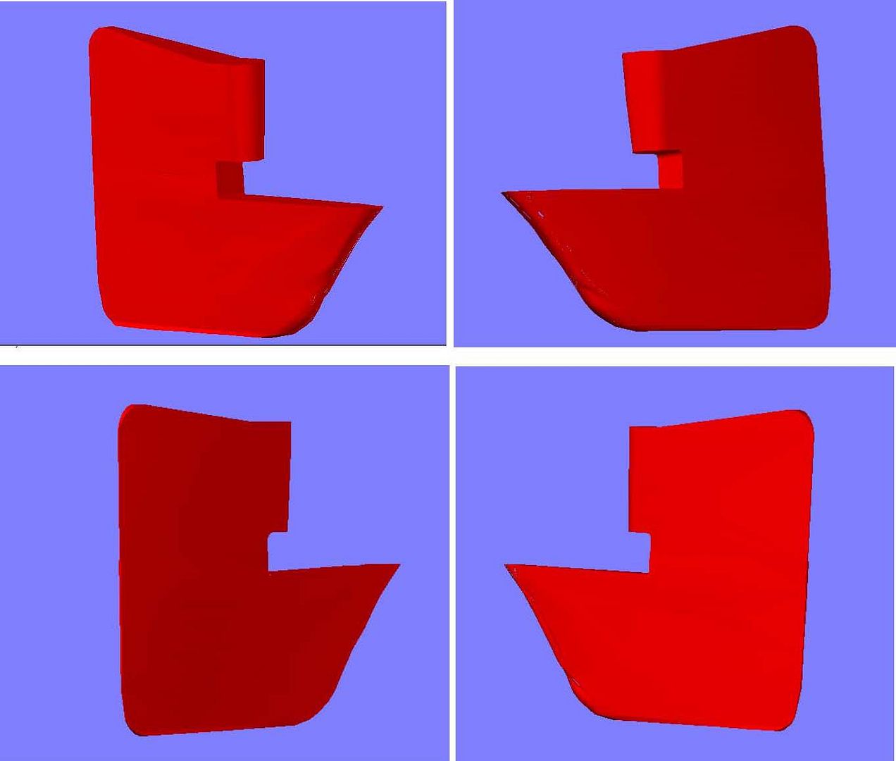
The next thing I did was cut out the torpedo tubes. I did this by first tracing the outlines from the plans, extending them well past the outline of the ship.
These rectangles were copied to the correct locations on the 3D hull, lofted and then subtracted. The remaining images on this post show the Batfish model as she currently stands.
I will post more as I get it done.
CHEERS!!!


Comment