1/144 Scale USS Batfish (SS310)

Collapse
X
 
  • Time
  • Show
Clear All
new posts
  • rdutnell
    Junior Member
    • Nov 2012
    • 388

    #16
    Re: 1/144 Scale USS Batfish (SS310)

    UPDATE 6

    Ola Mi Amigos! The journey continues…

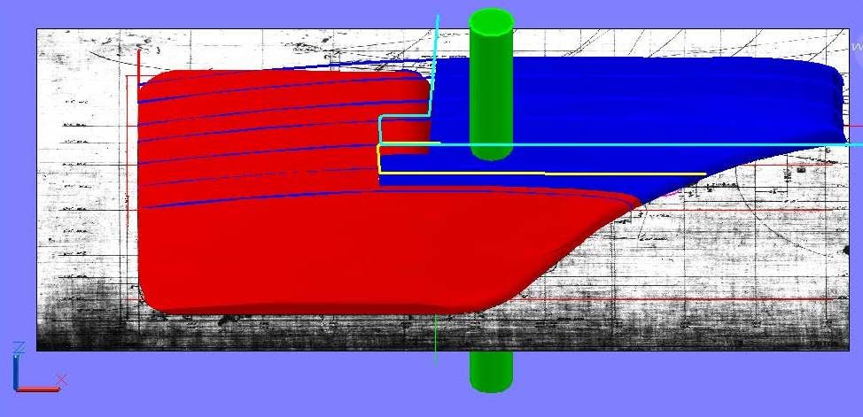
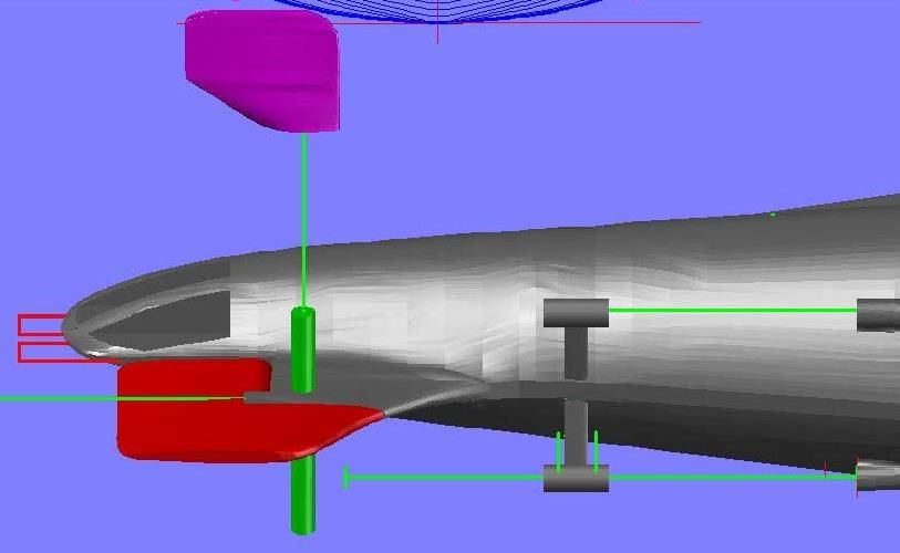
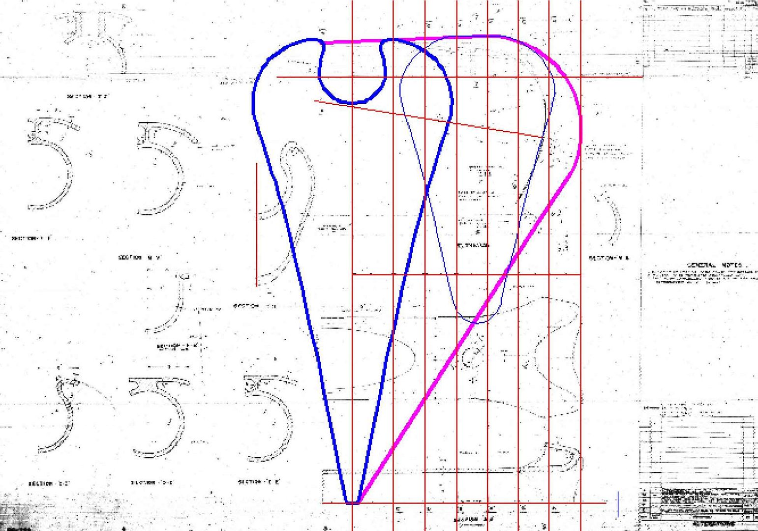
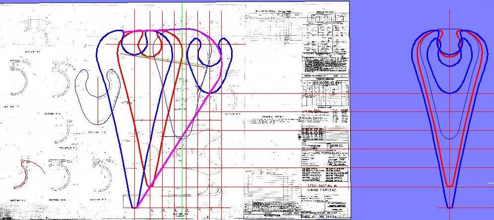
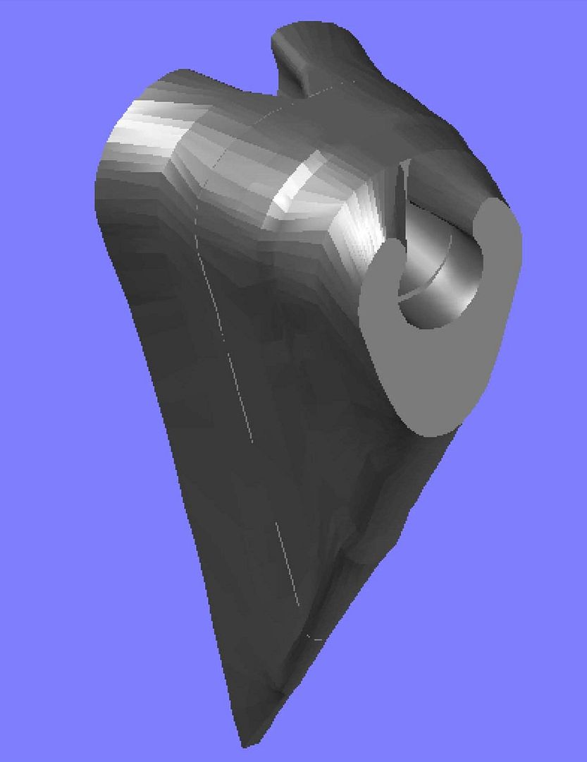
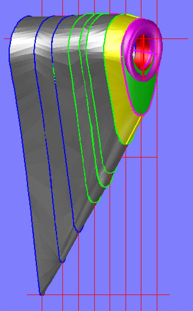
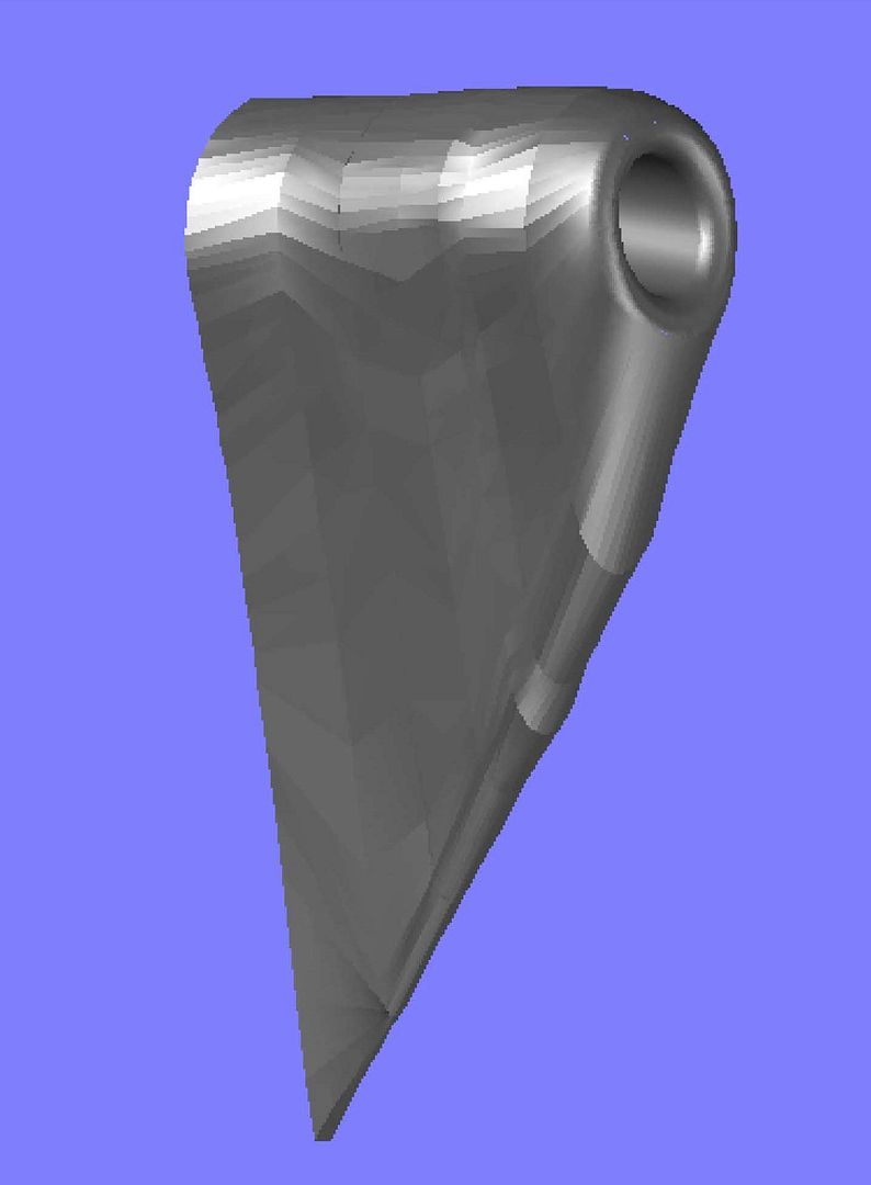
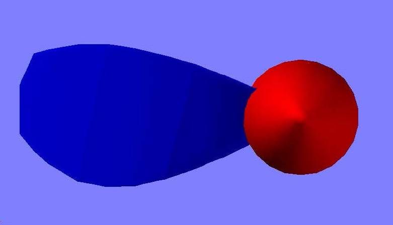
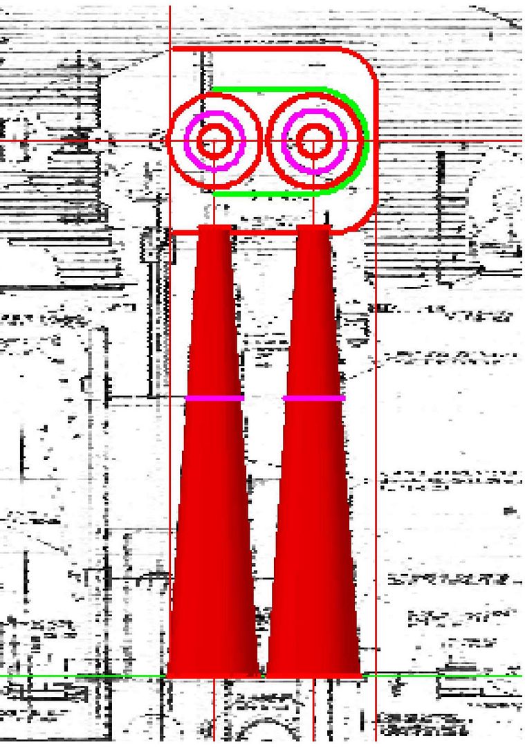
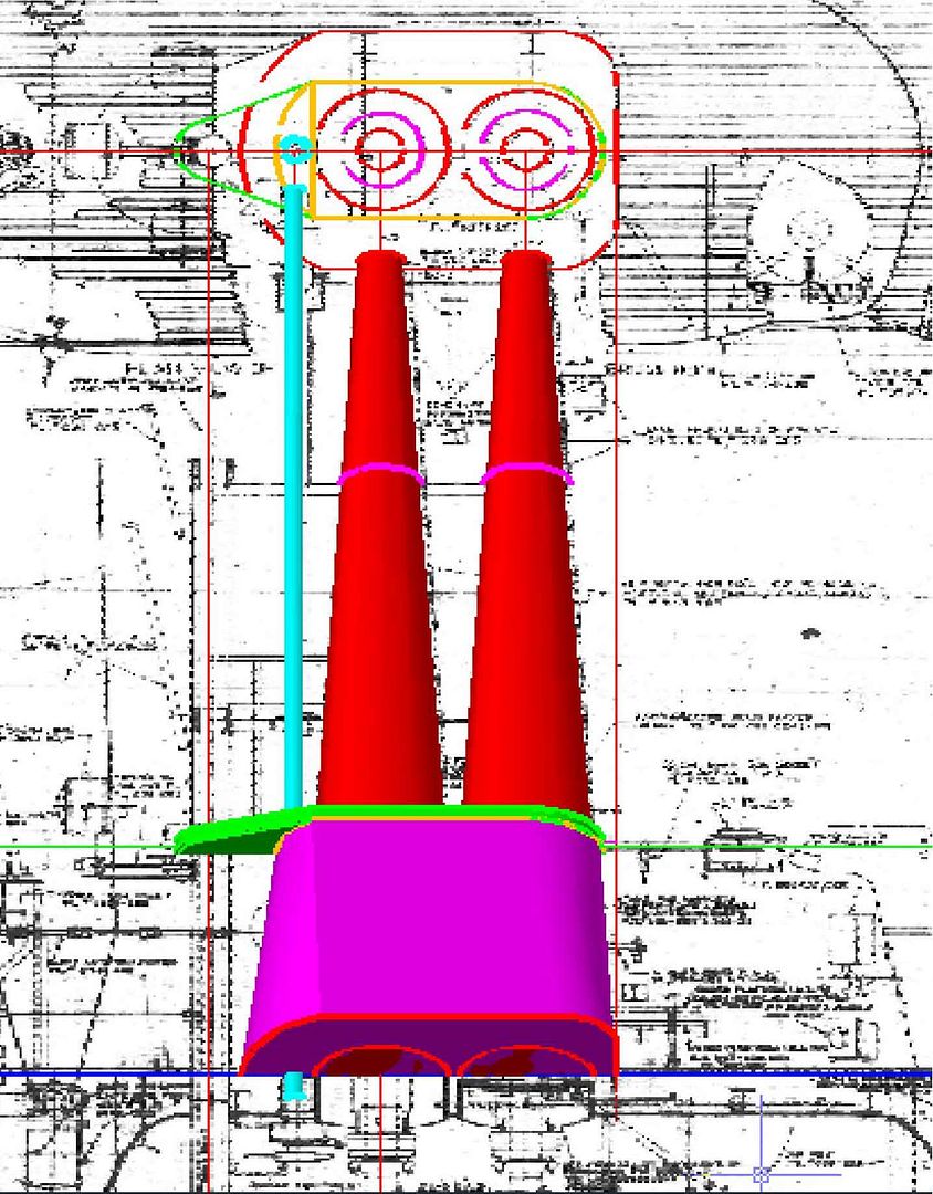
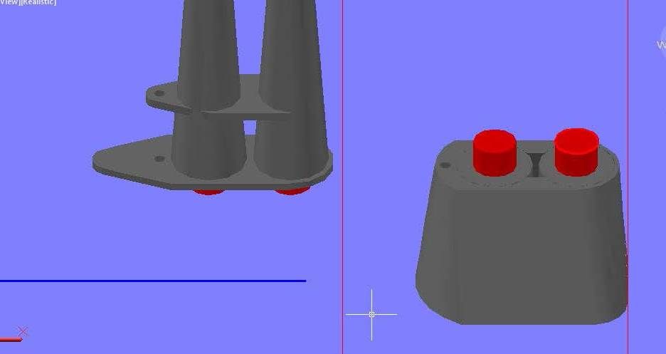
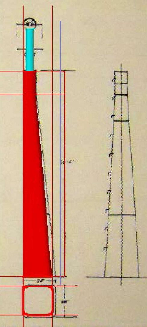
    Before starting the sternpost, I realized that I needed to drill a shaft hole in the rudder. I did this by aligning a circle in the proper position and extruding it.


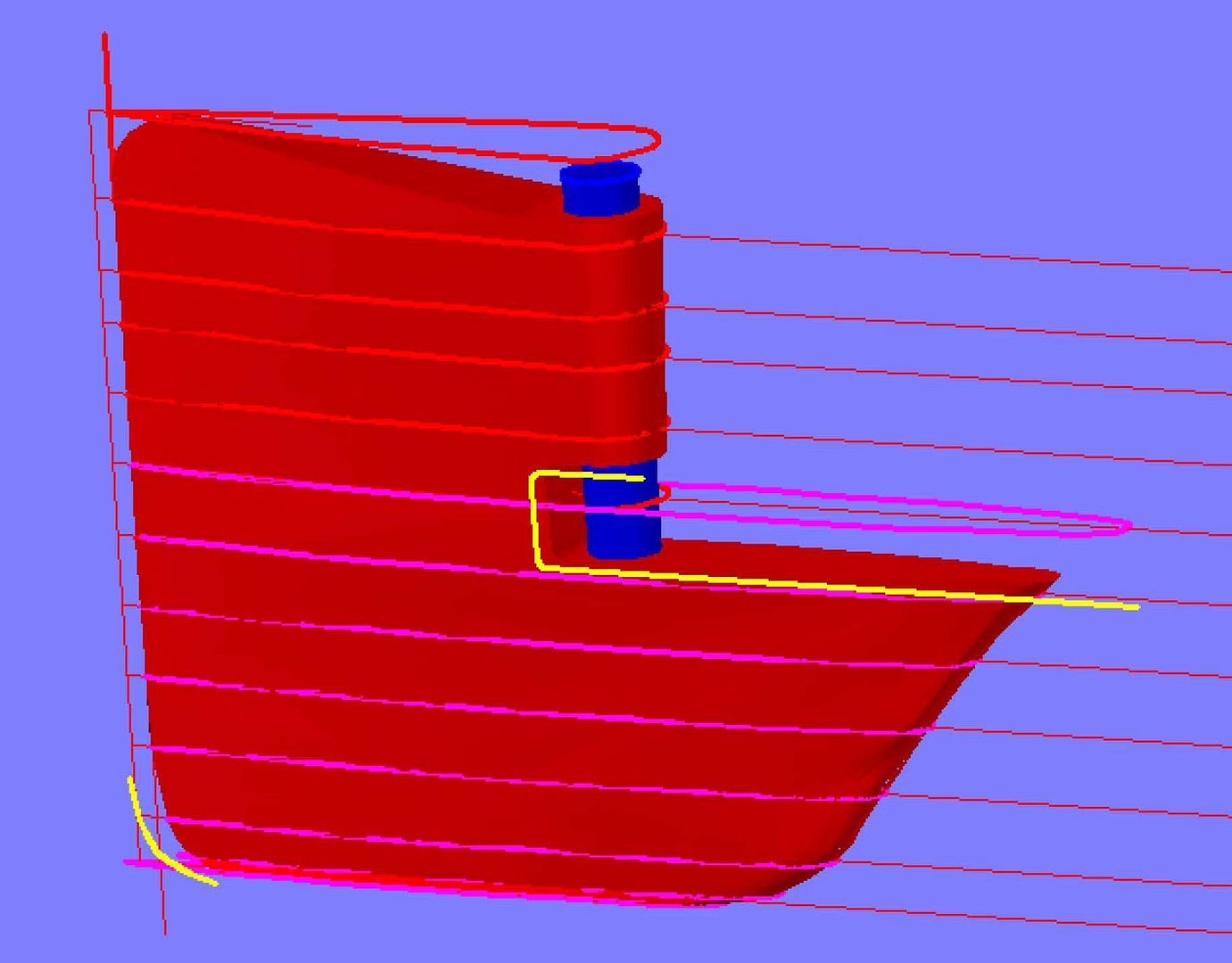
    I then subtracted the cylinder from the rudder. Note that I didn’t “drill” too far into the lower rudder, leaving only a shallow hole for the shaft to sit in.


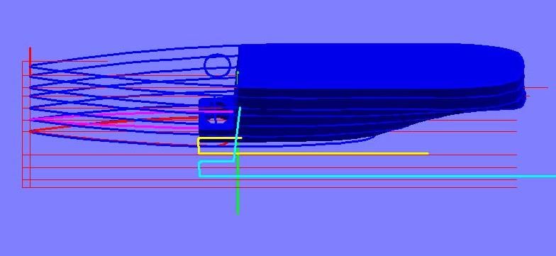
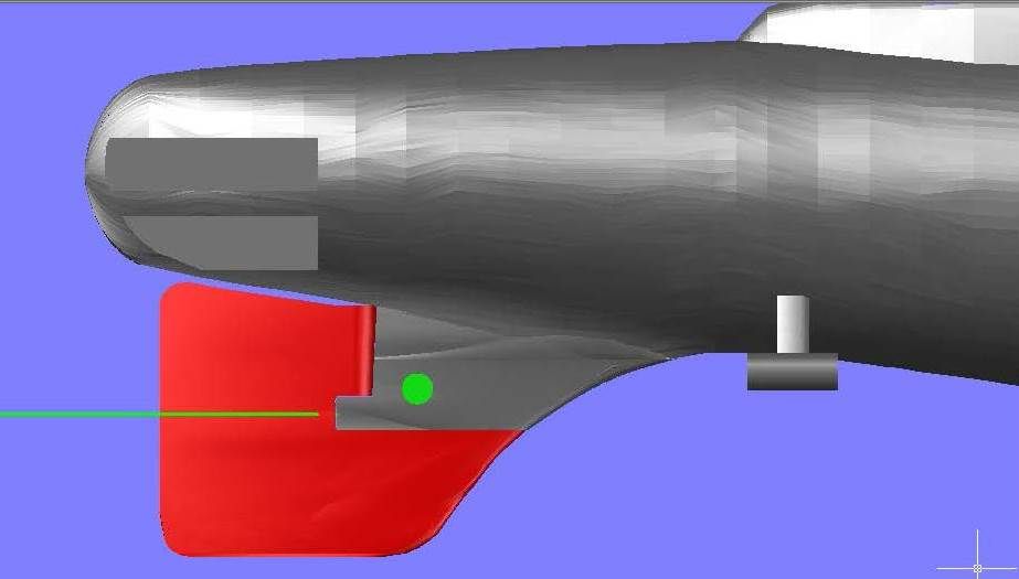
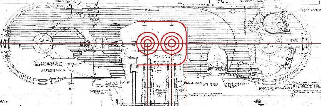
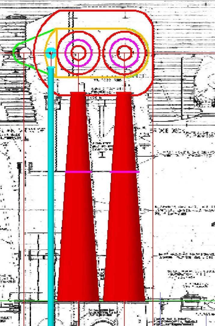
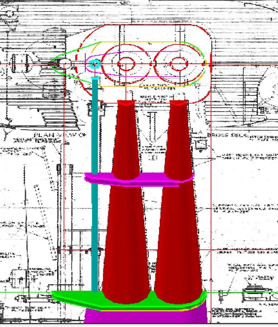
    Before I started on the sternpost, I copied the rudder to the Batfish drawing to see what it looked like and to make sure the dimensions were good.


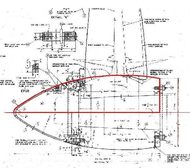
    I liked what I saw, except that the sternpost on the model was too long, so I sliced it off fairly close to the hull.


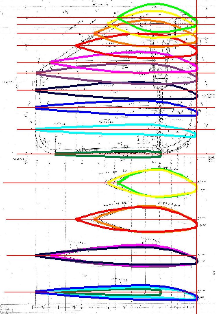
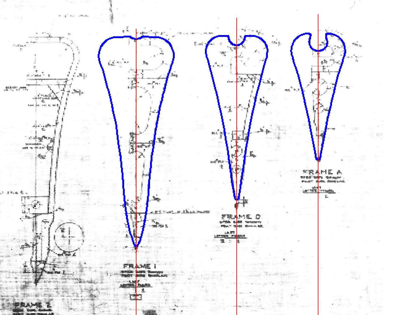
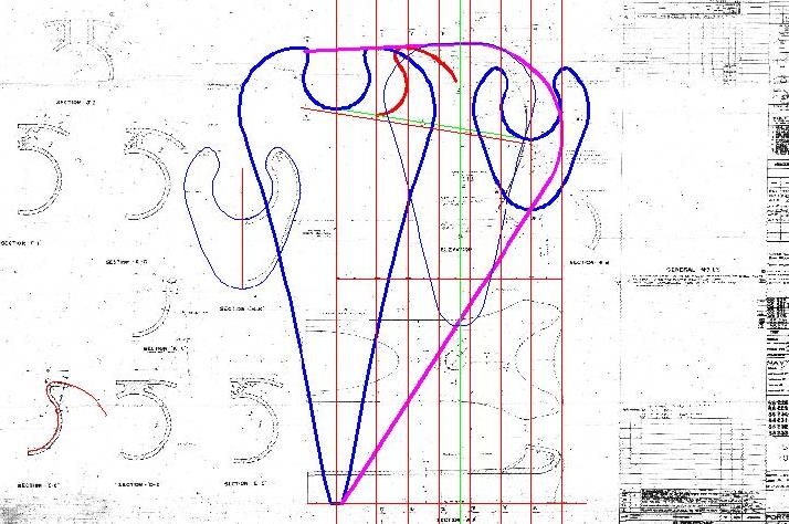
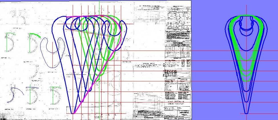
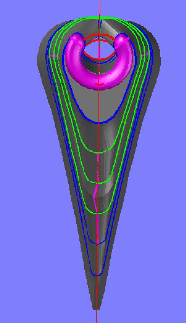
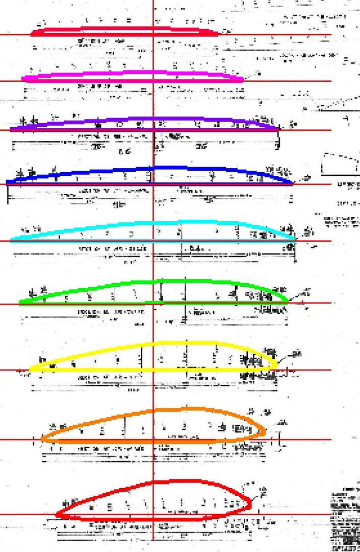
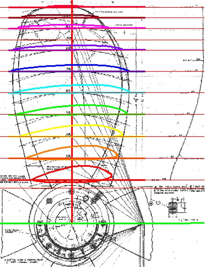
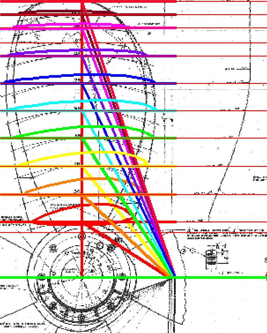
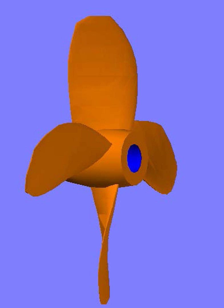
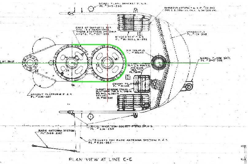
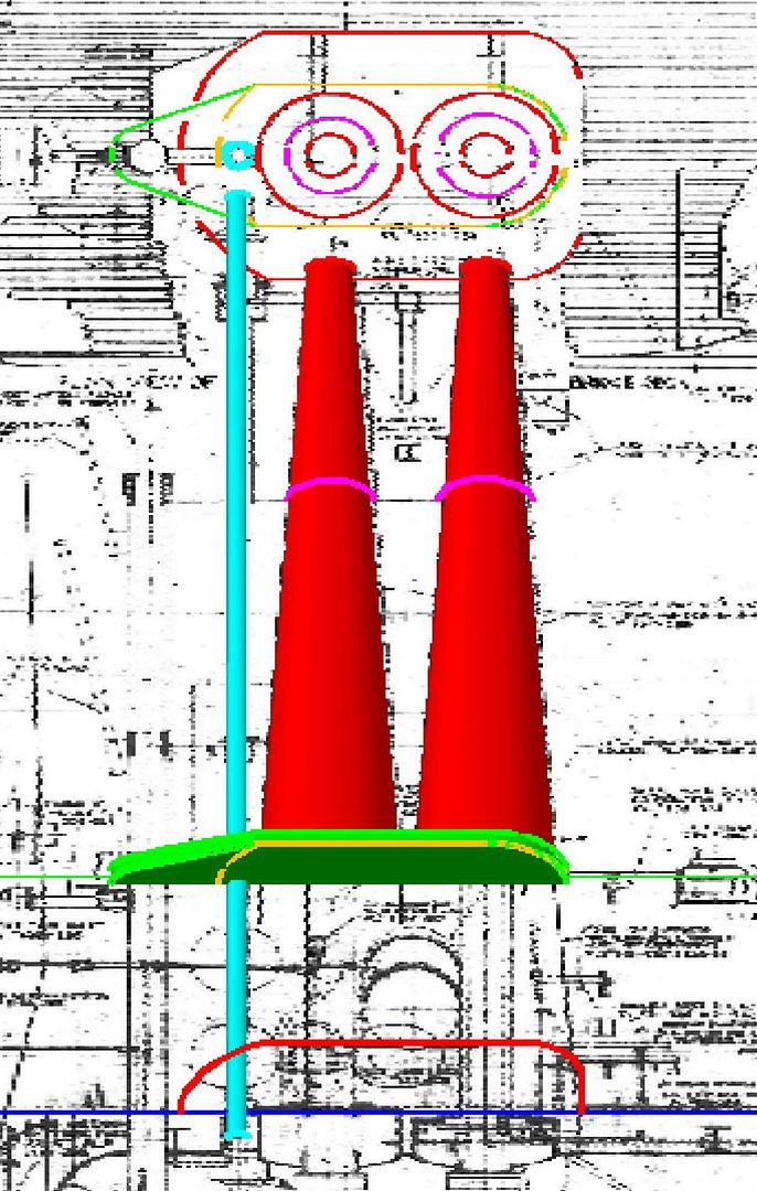
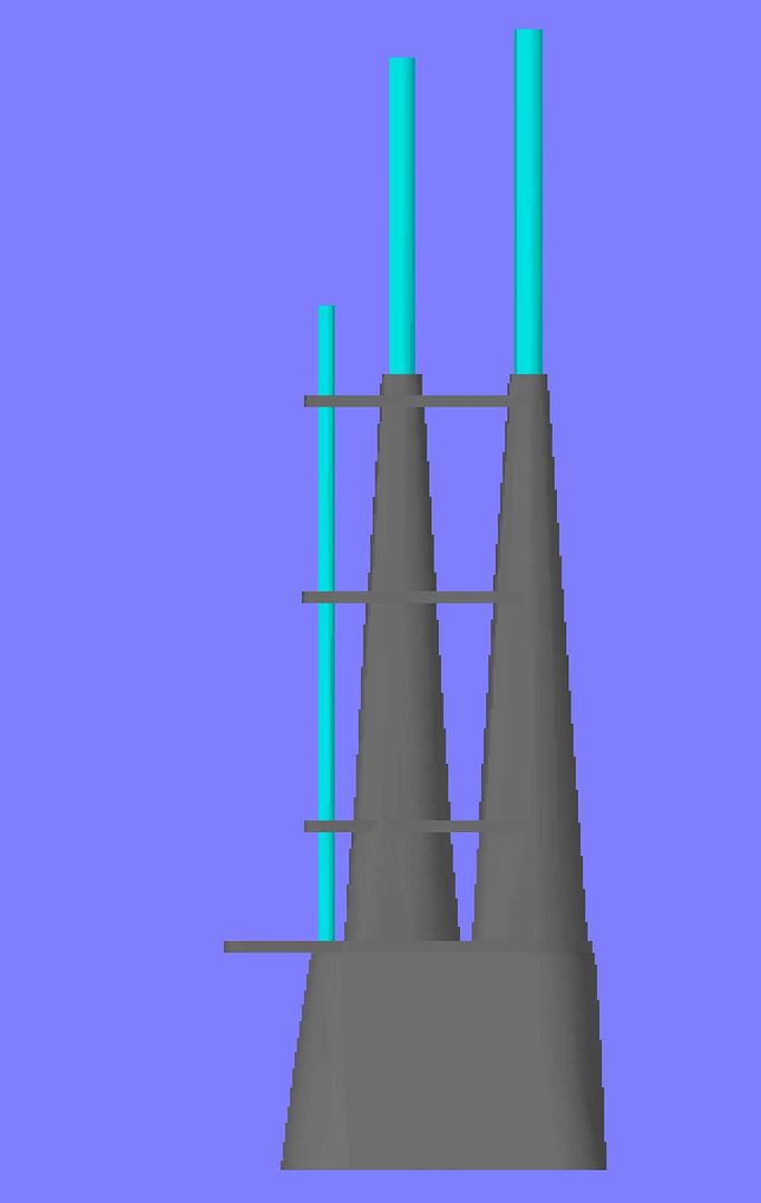
    I did the sternpost in much the same manner as I did the rudder. I began by tracing the sections…


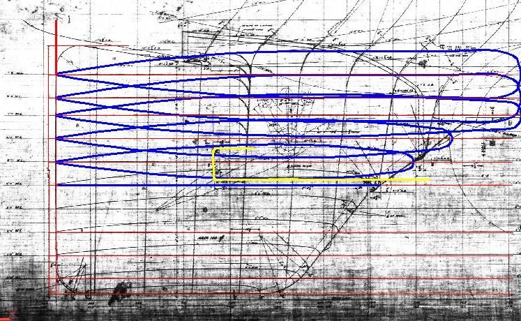
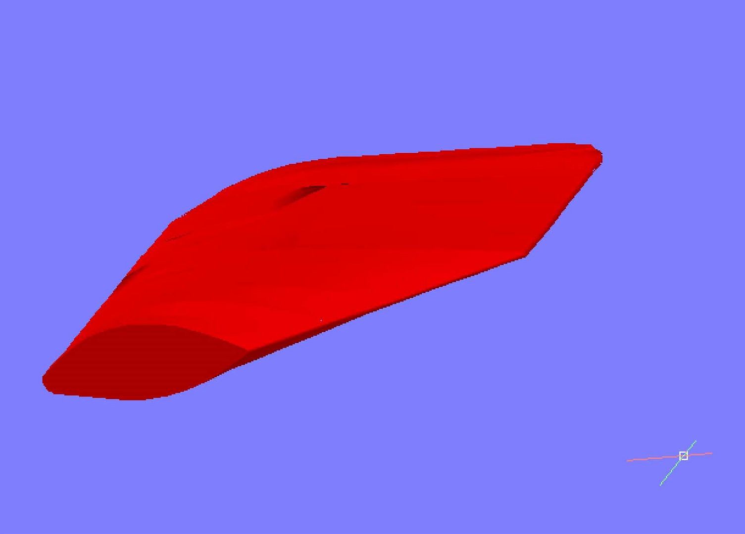
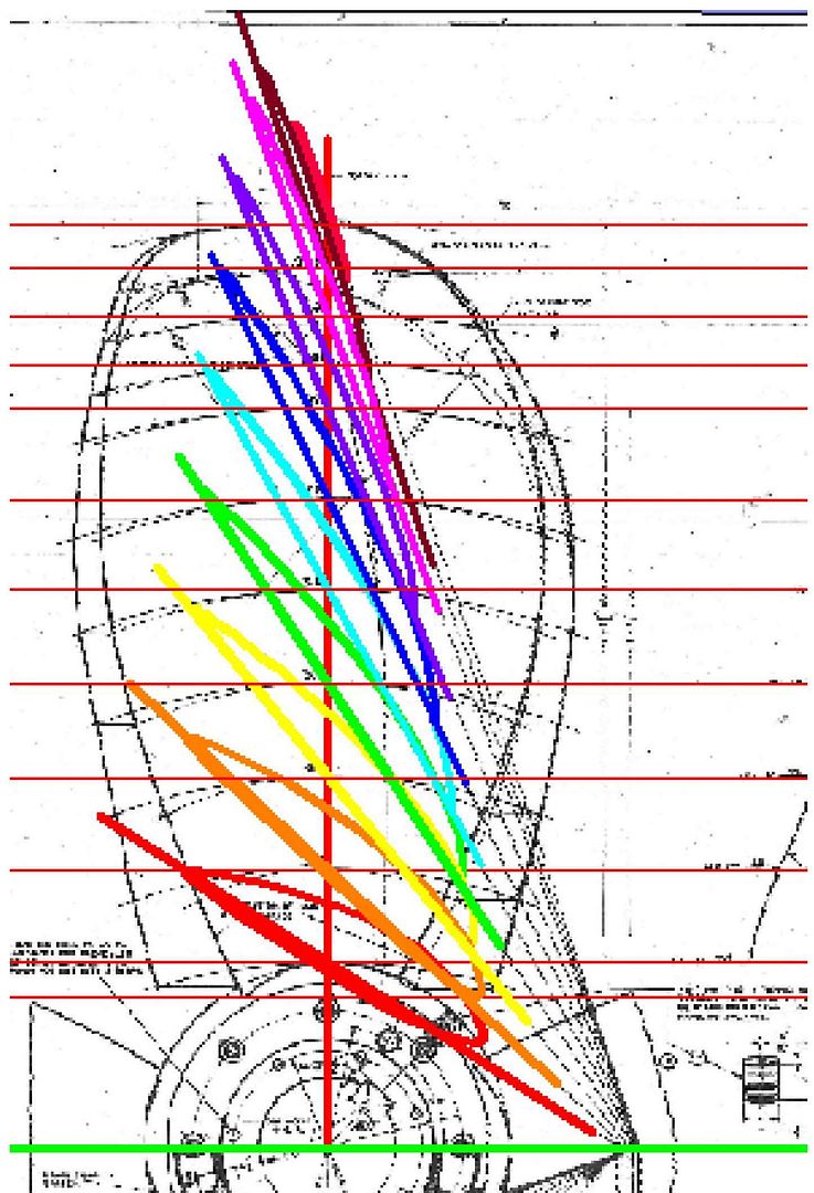
    …Then rotating and lofting them.


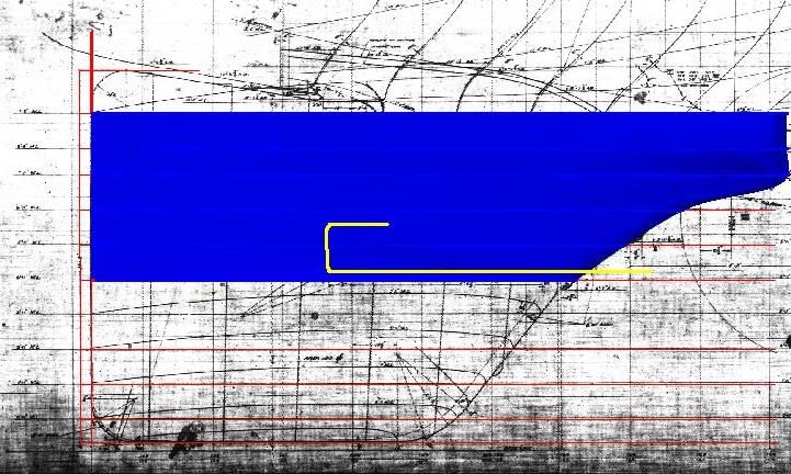
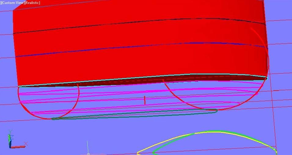
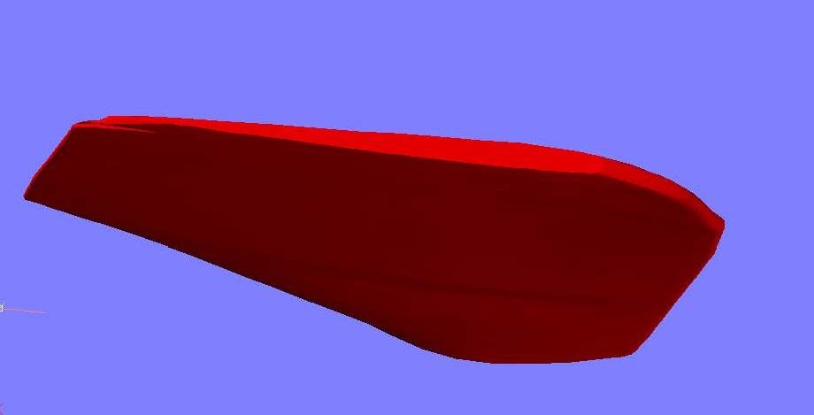
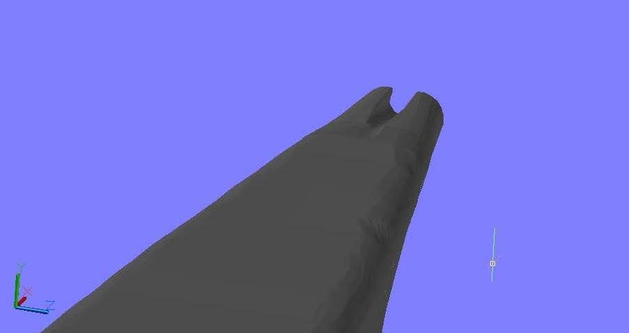
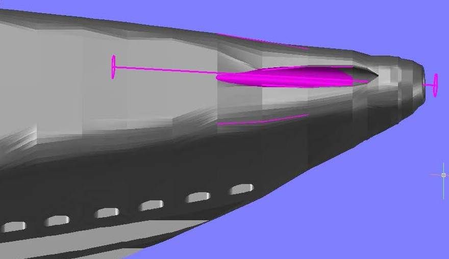
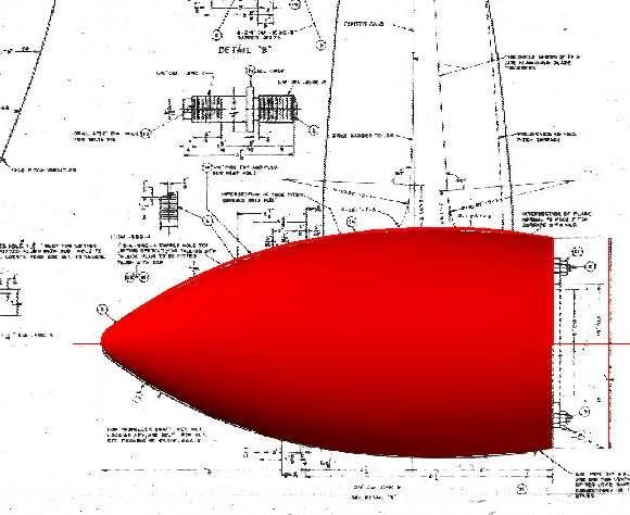
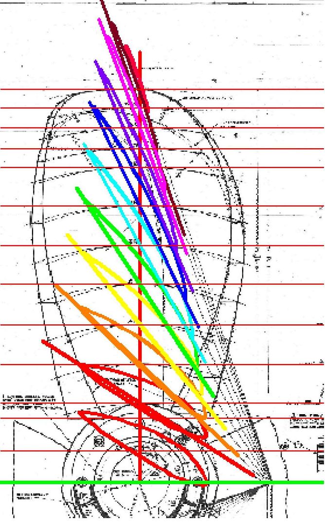
    The next step was to slice it to the proper shape.


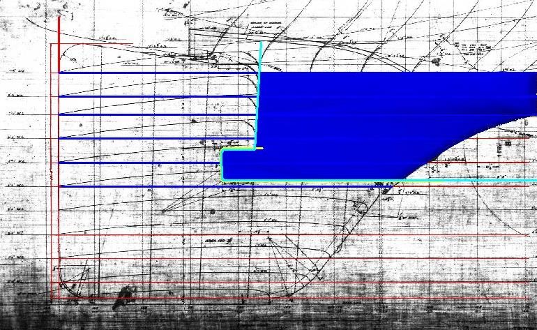
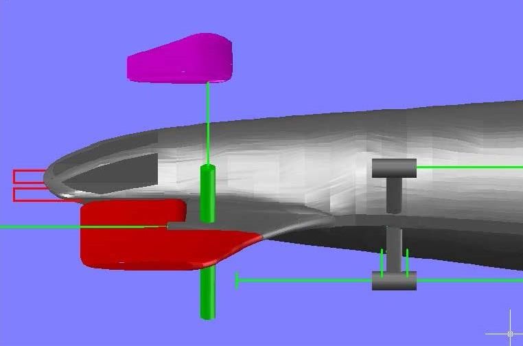
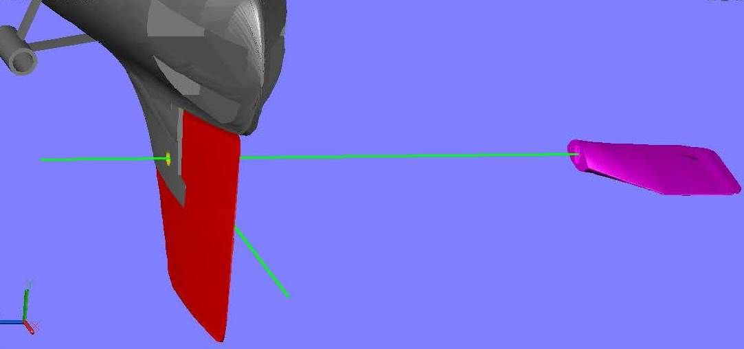
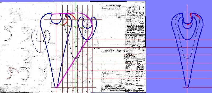
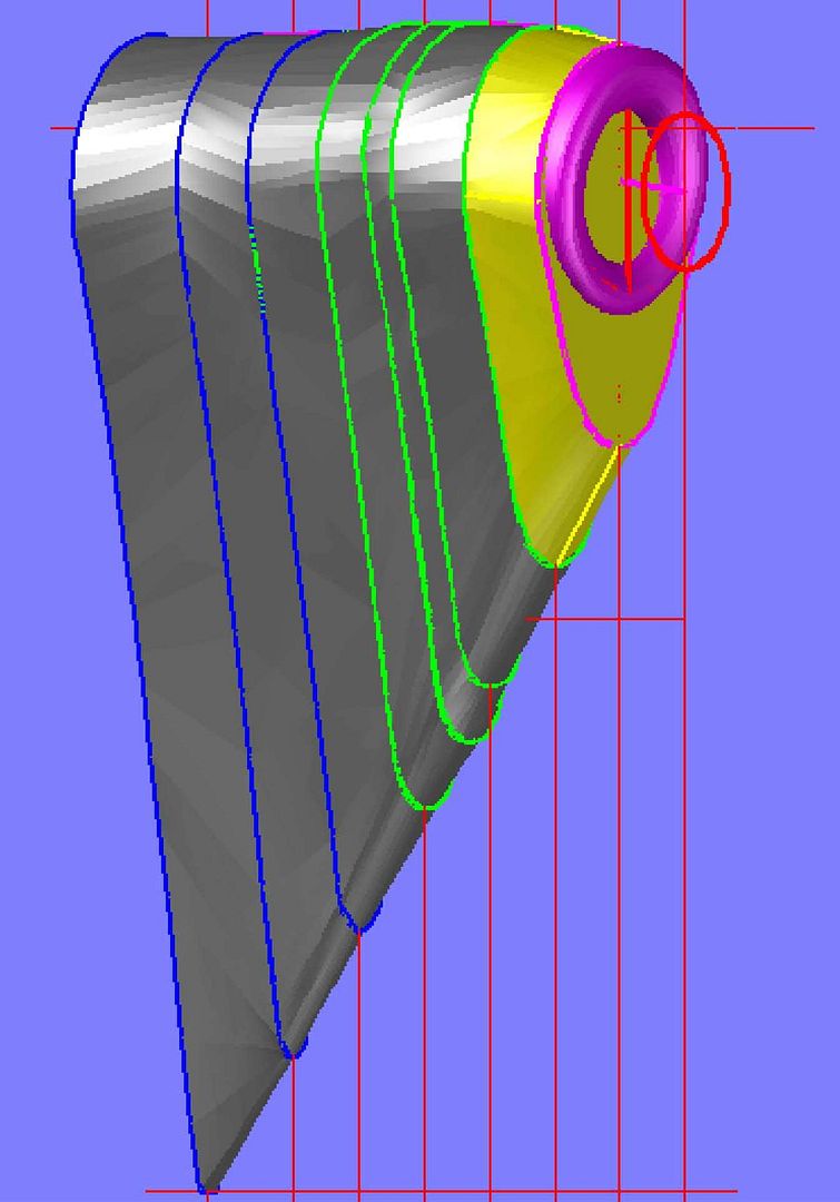
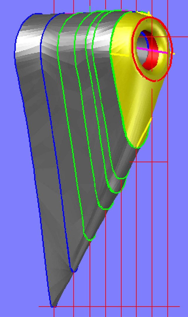
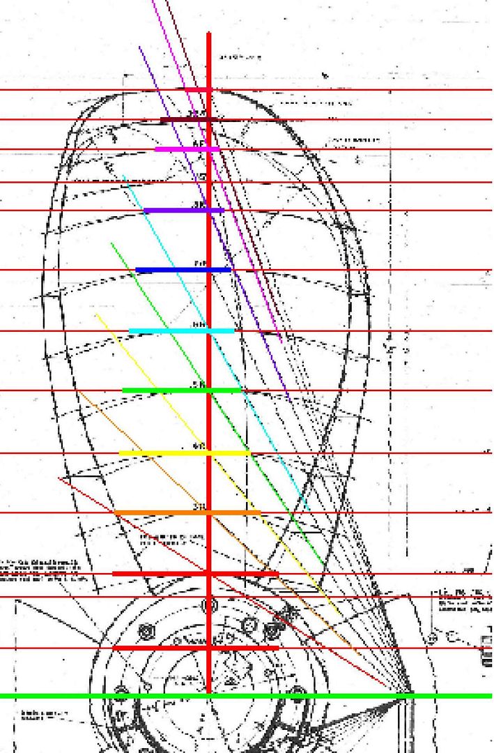
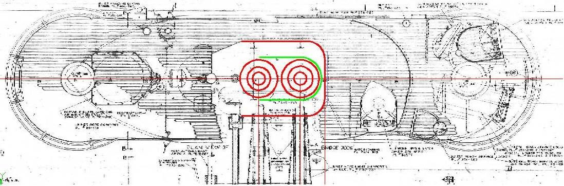
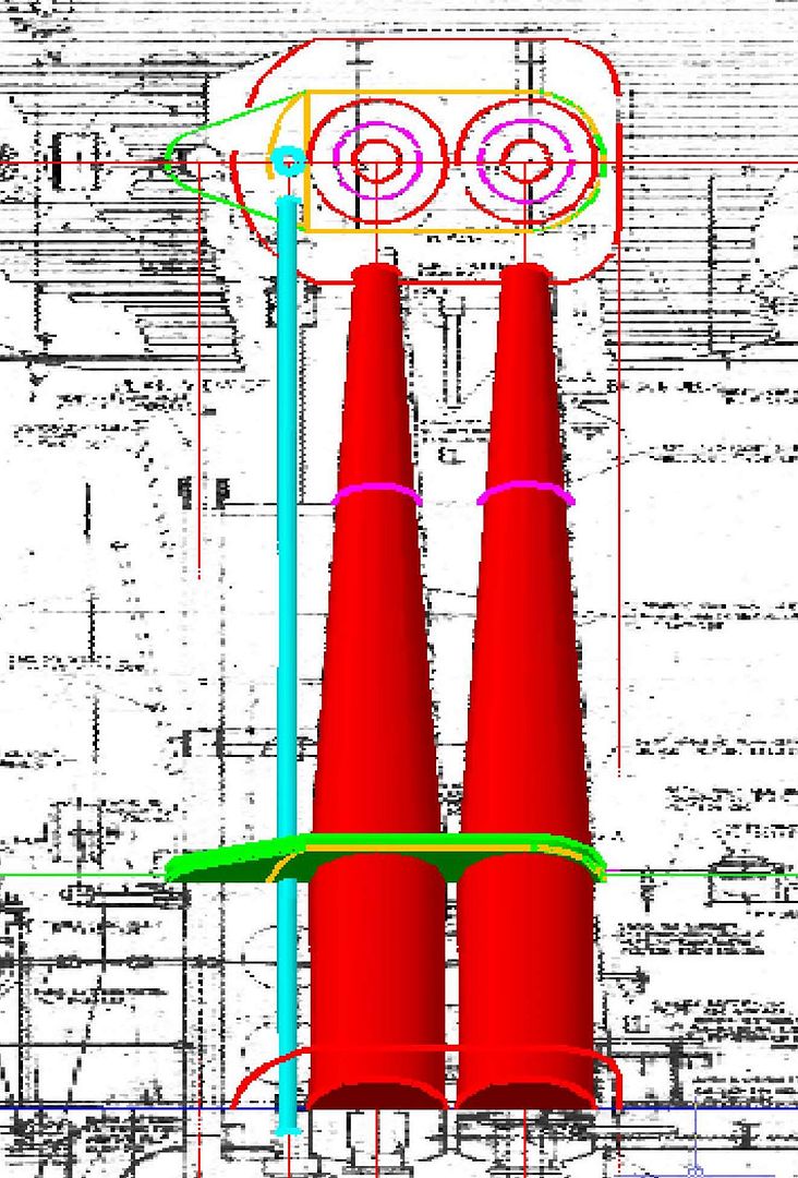
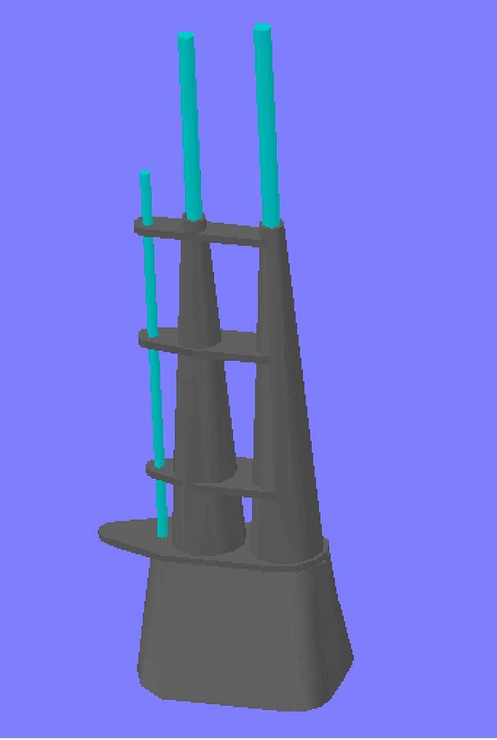
    To this point, I had the rudder layer turned off. Turning it back on revels that the alignment looked good…


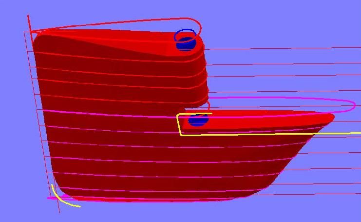
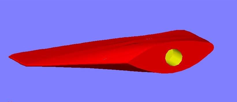
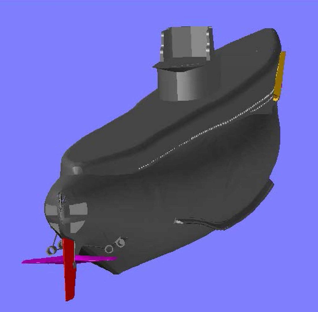
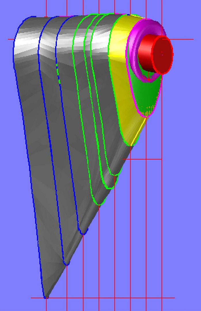
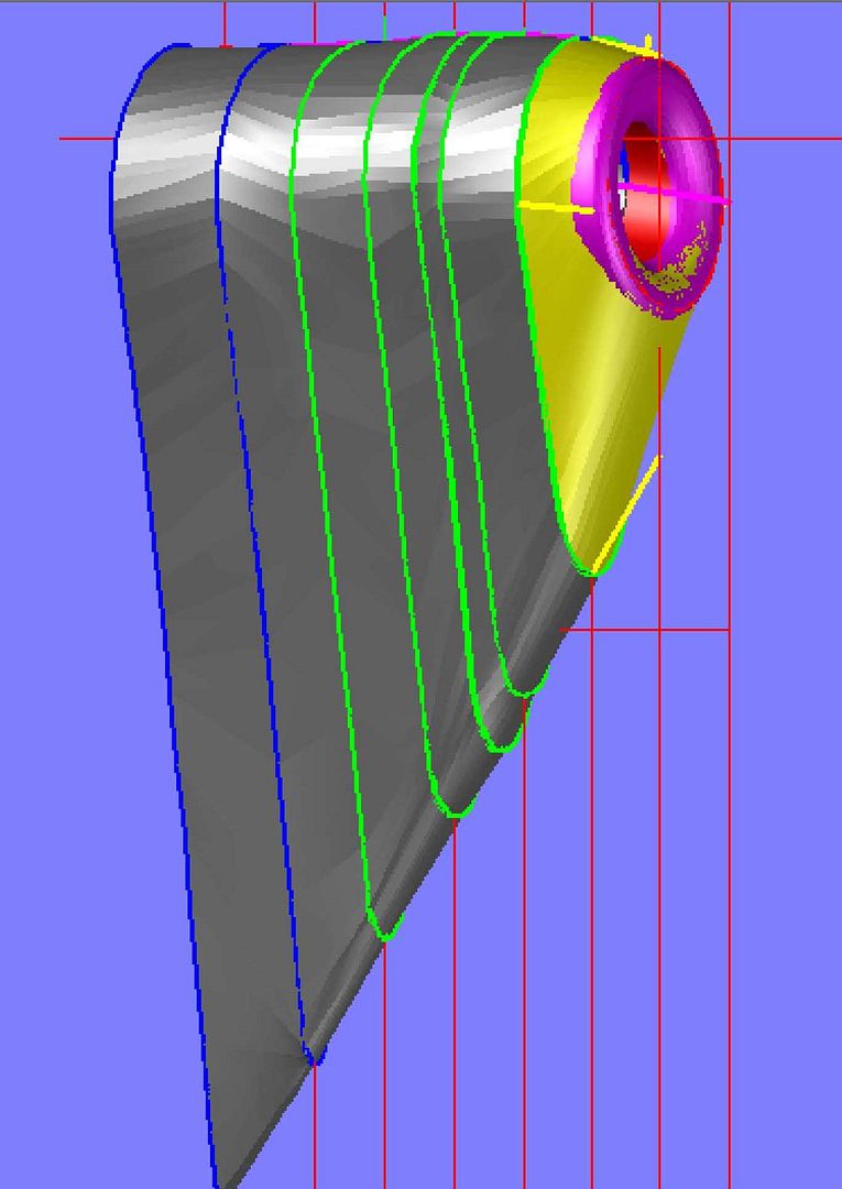
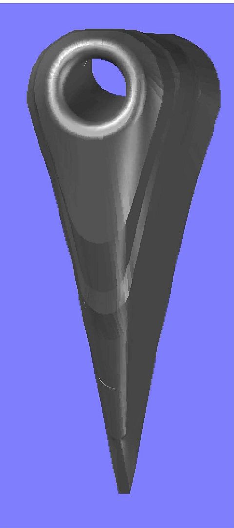
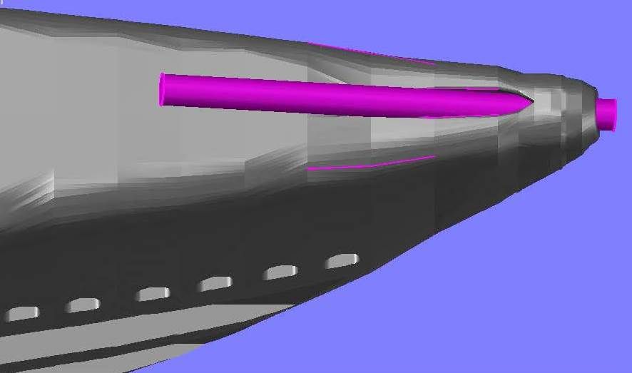
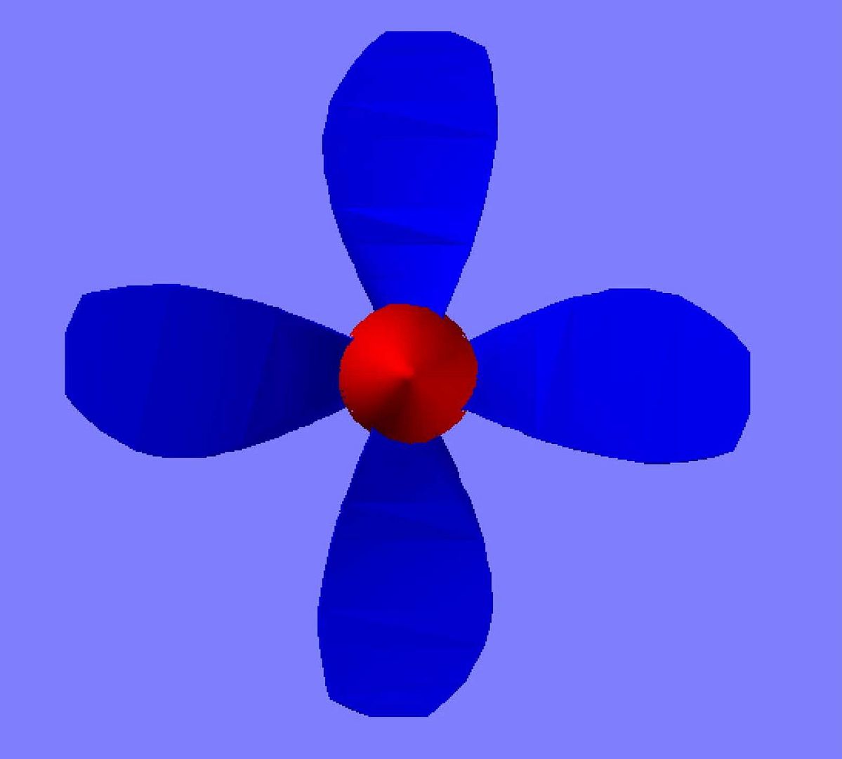
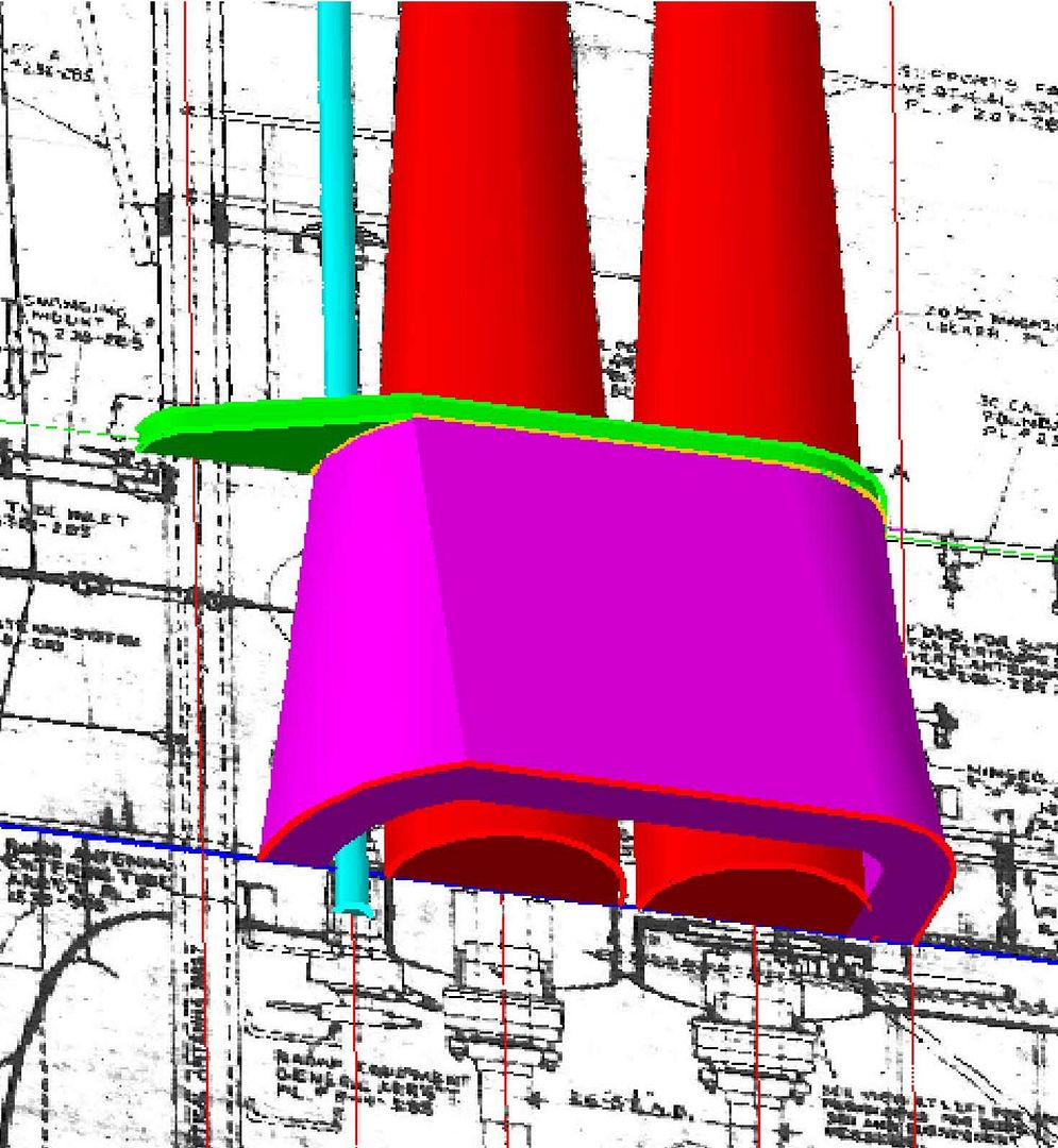
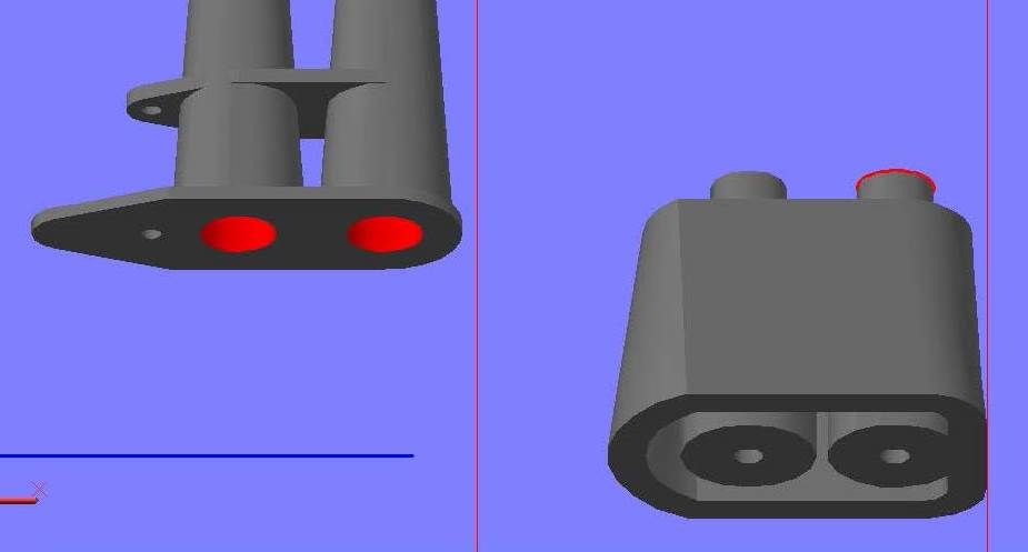
    … So, using the same circle as I did with the rudder, I extruded a cylinder through the sternpost and subtracted it.


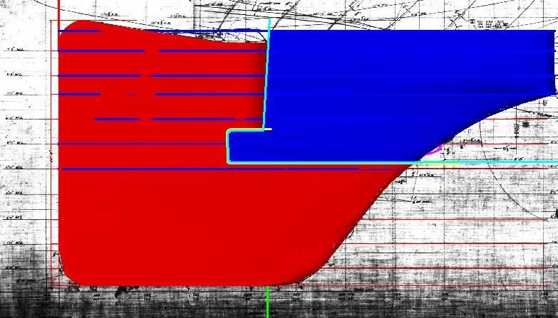
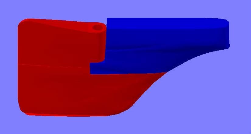
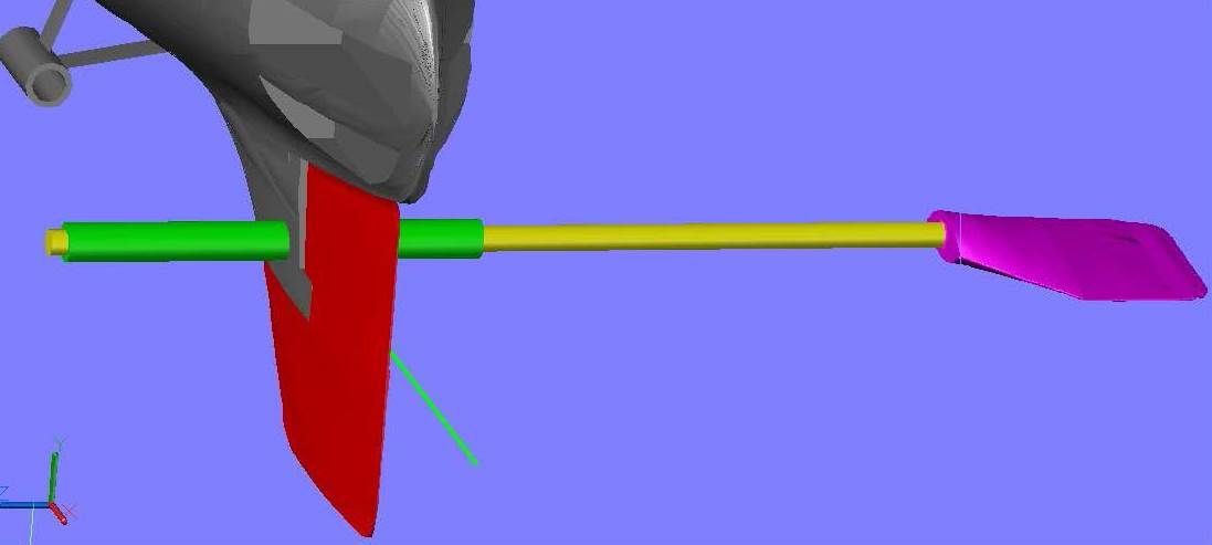
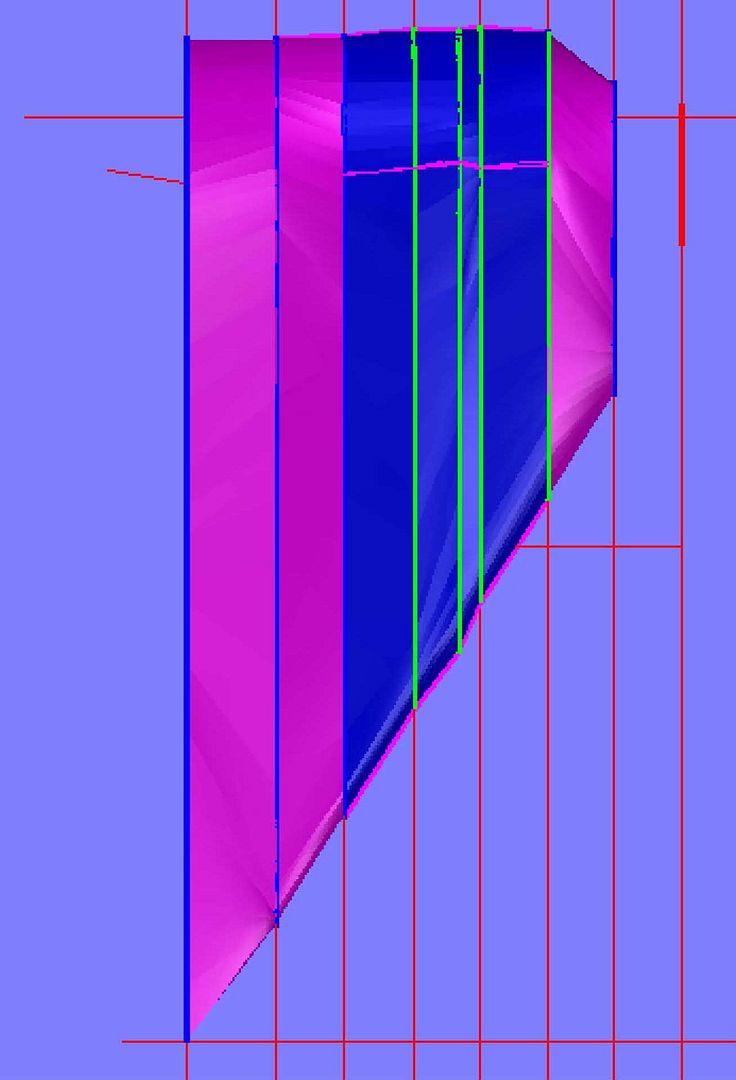
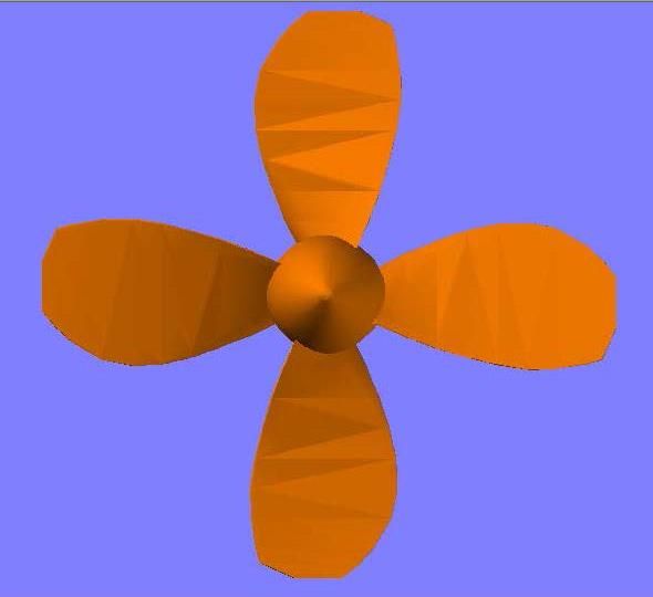
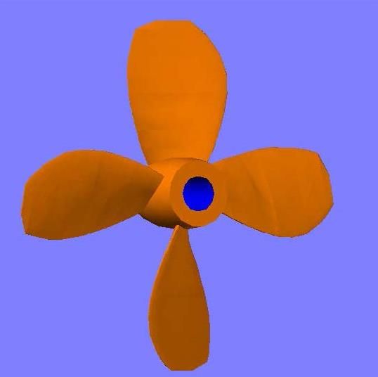
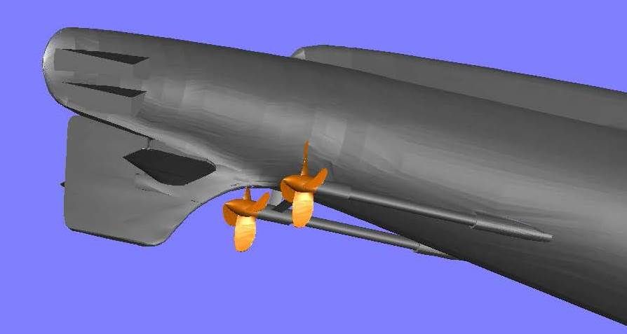
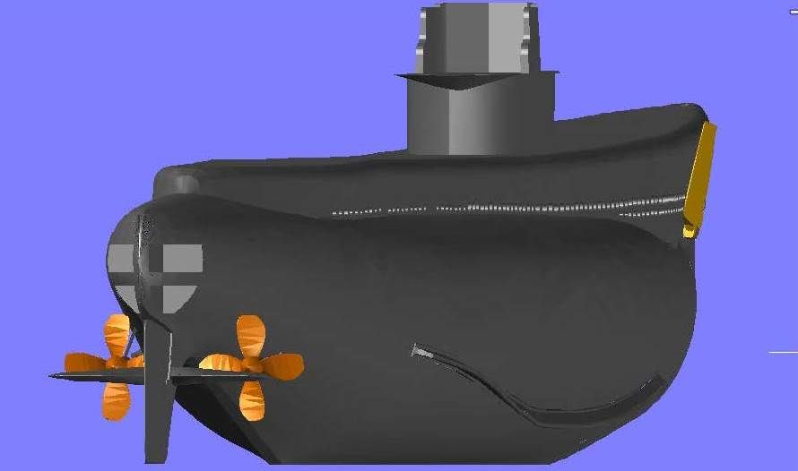
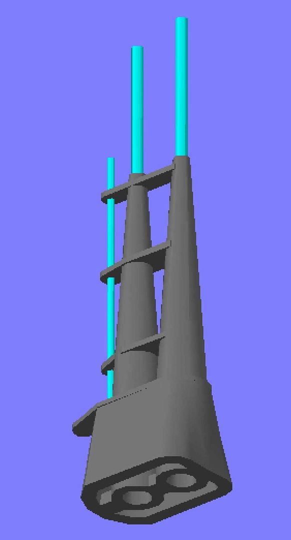
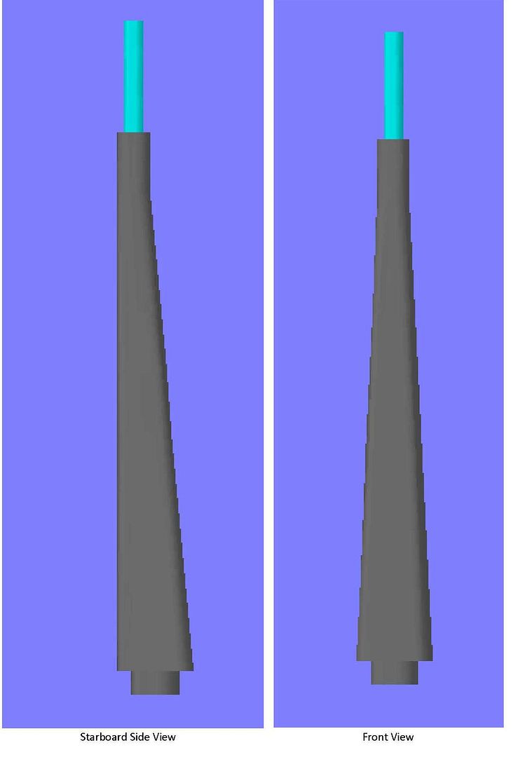
    The completed assembly is shown below.


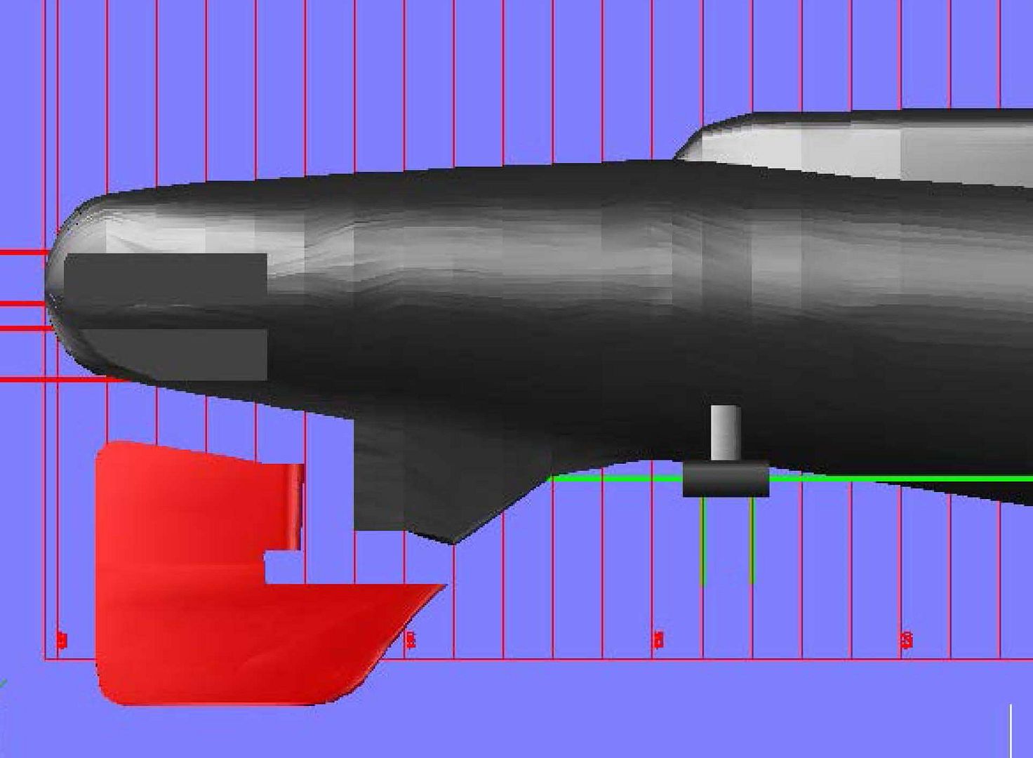
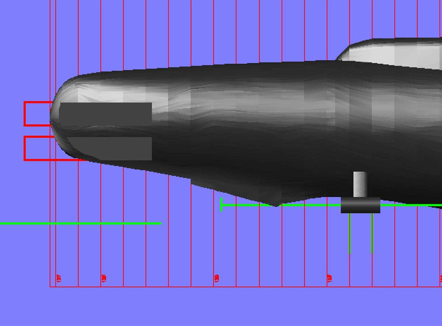
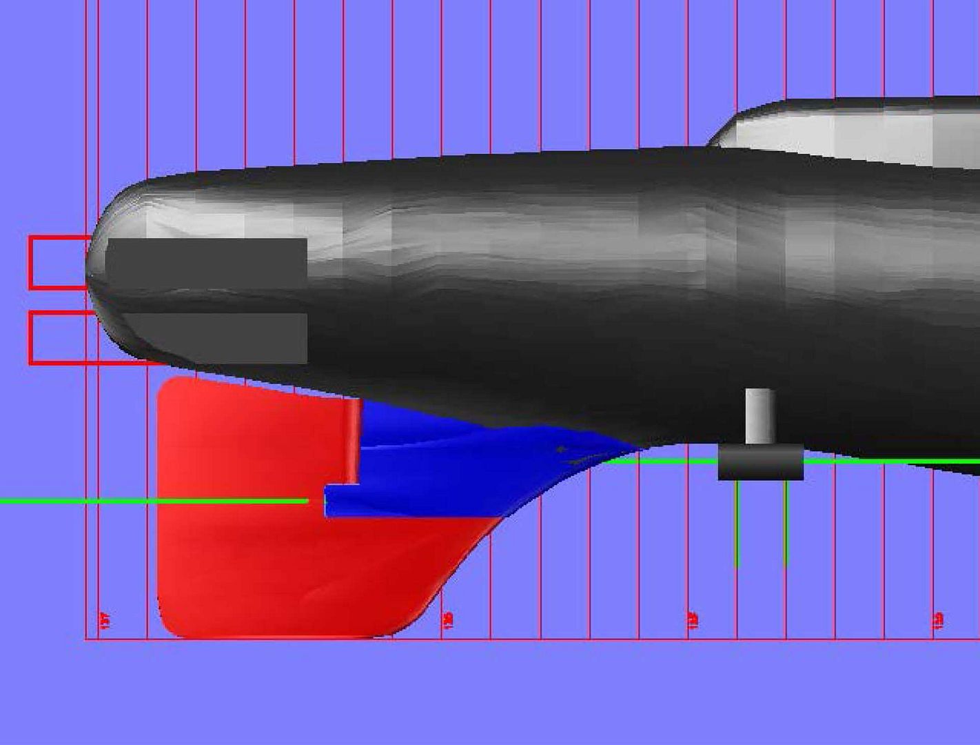
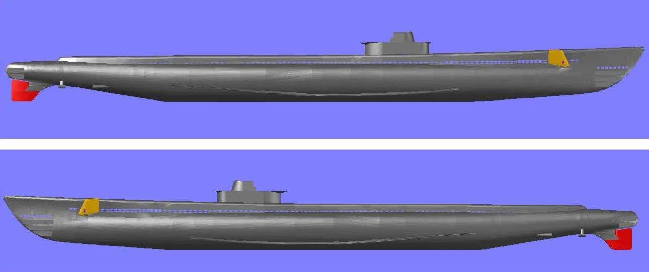
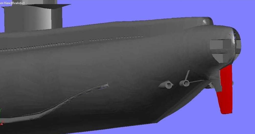
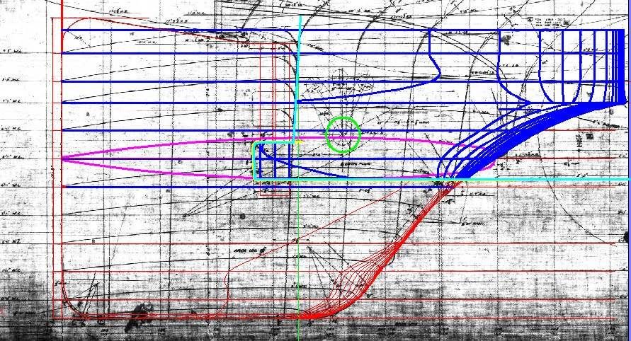
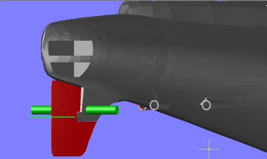
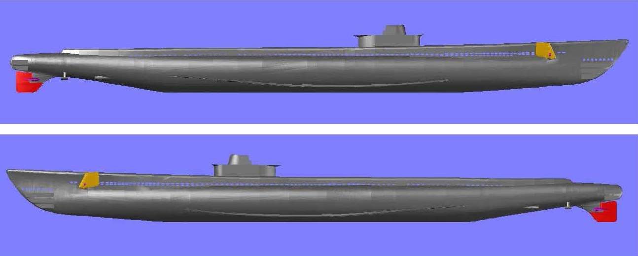
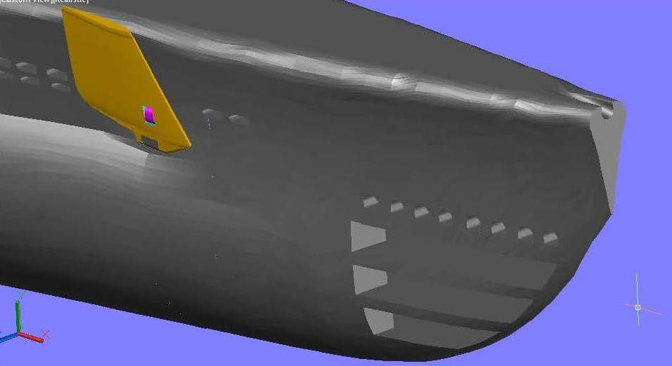
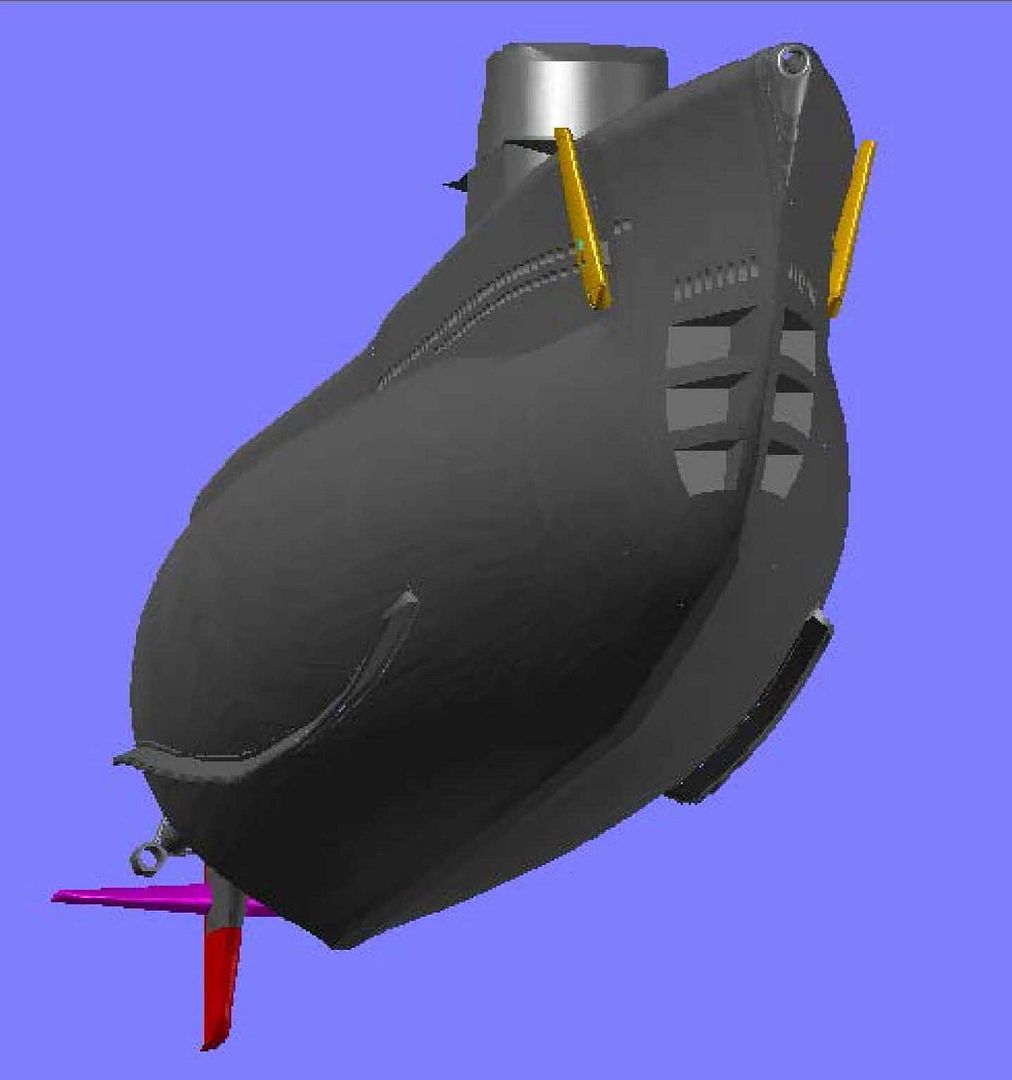
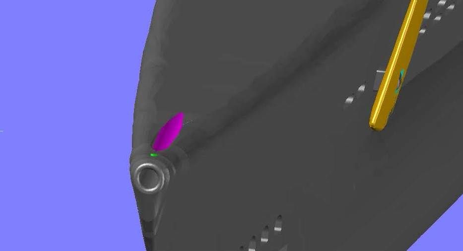
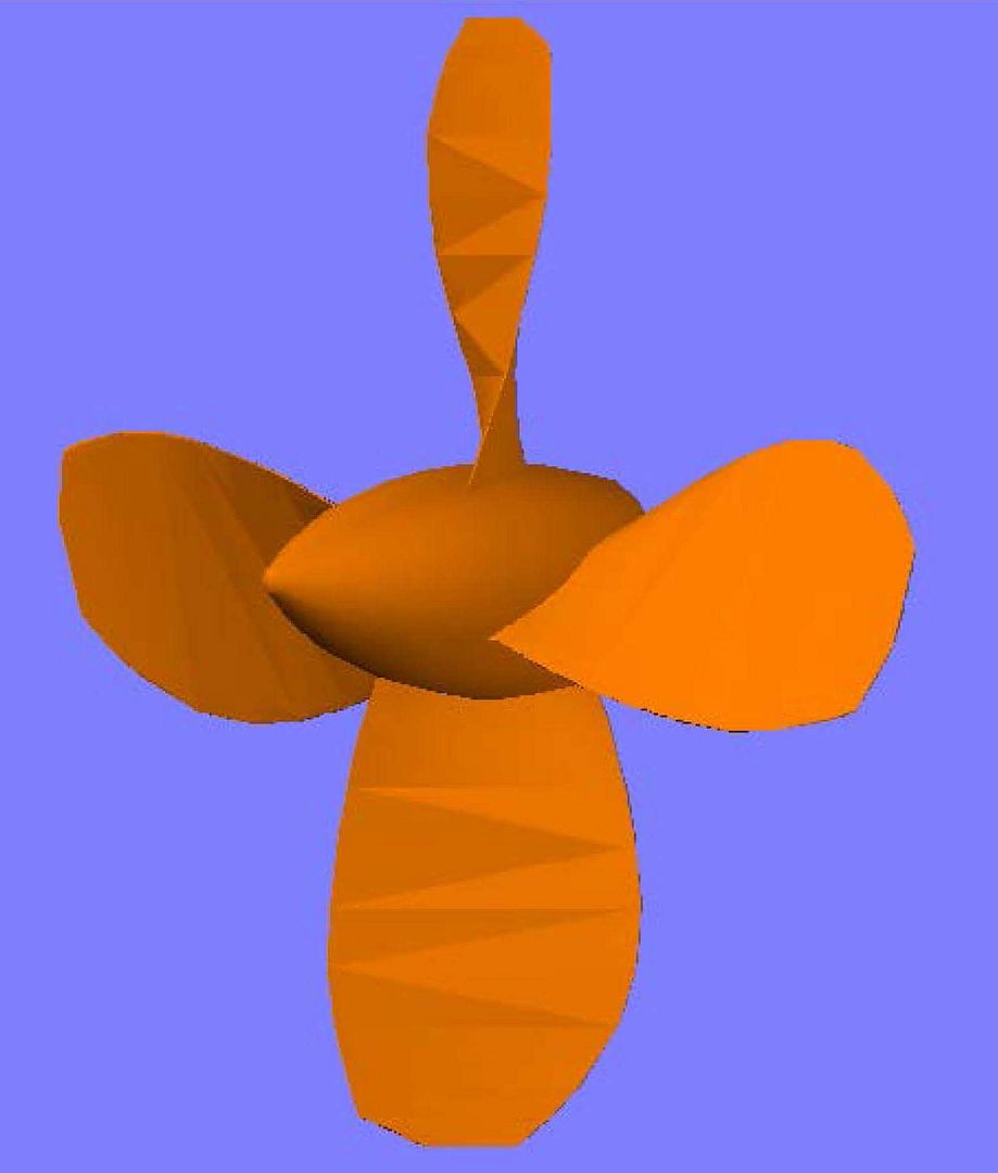
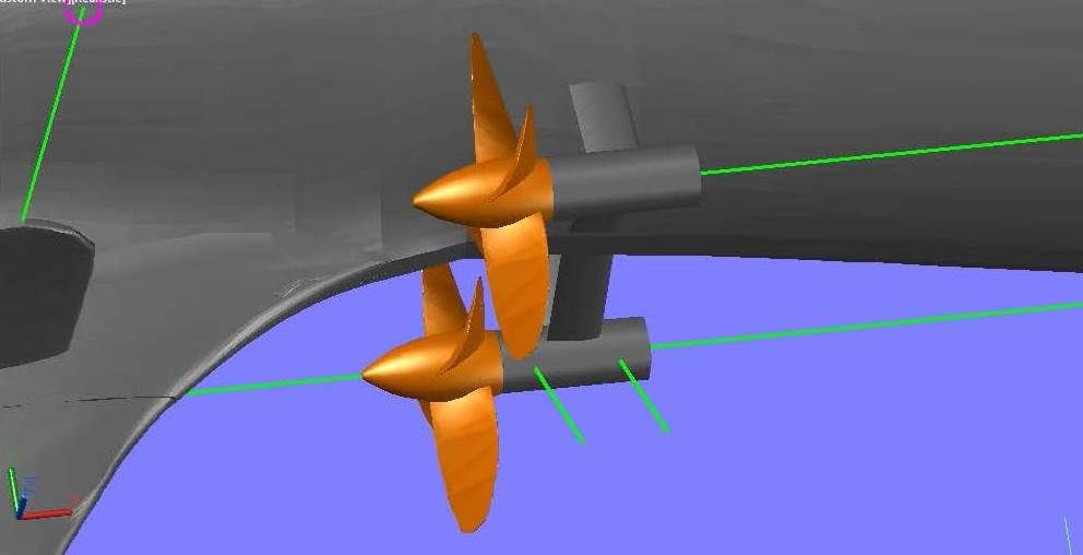
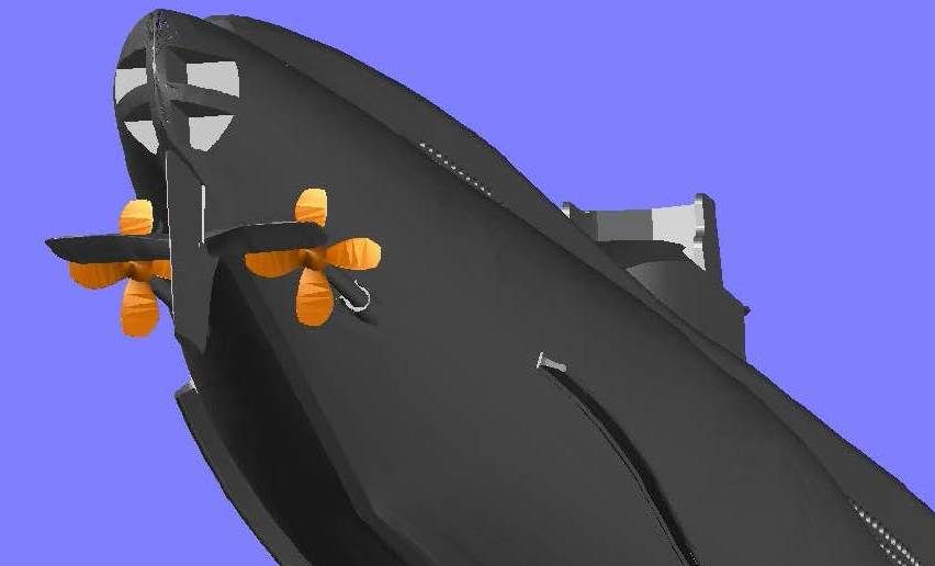
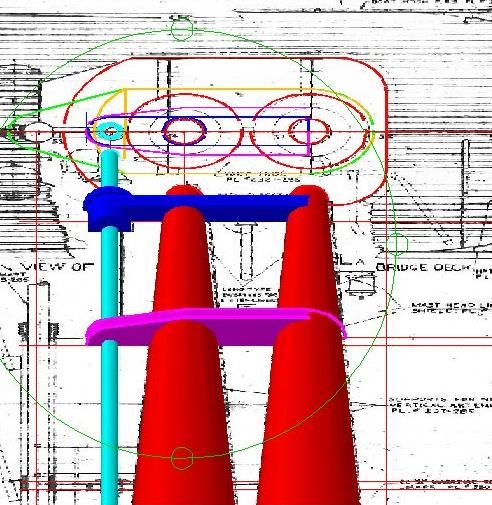
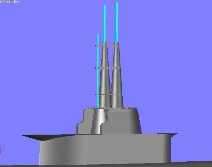
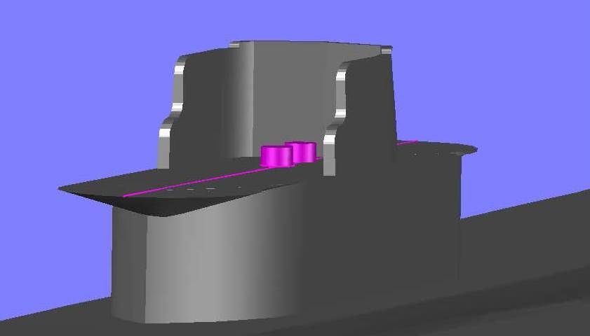
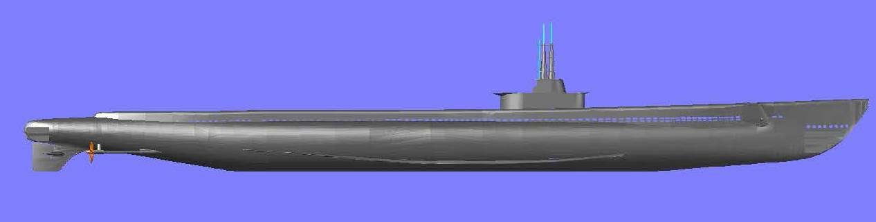
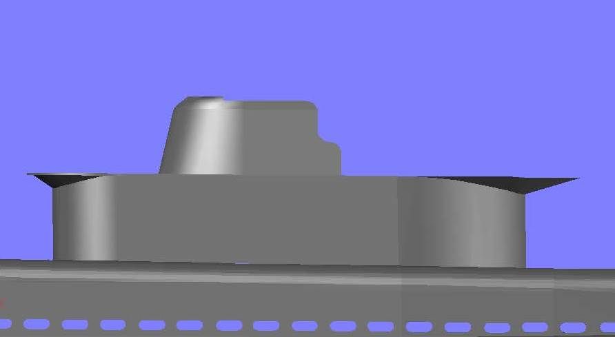
    With the assembly completed, the next step was to copy and paste it into the Batfish drawing. I knew, more or less, what the horizontal positioning was, so I started by positioning the assembly at that point, but, in the end, the final positioning was done by eyeball. As you can see, this resulted in good alignment, and the two objects blend nicely into one another.


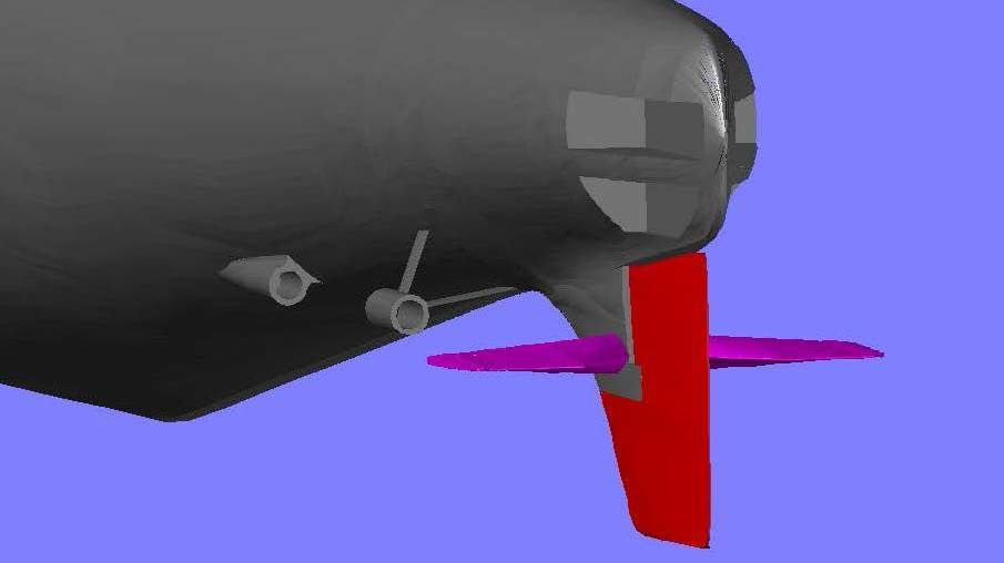
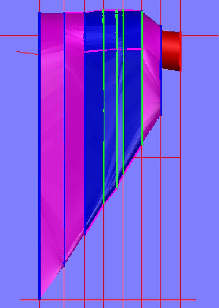
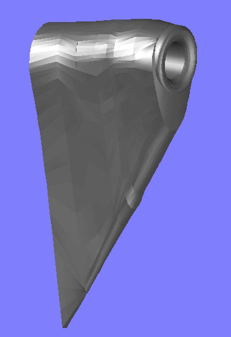
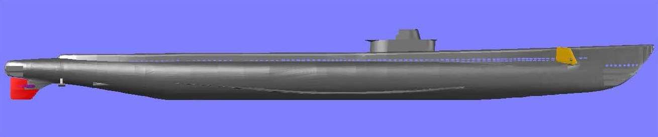
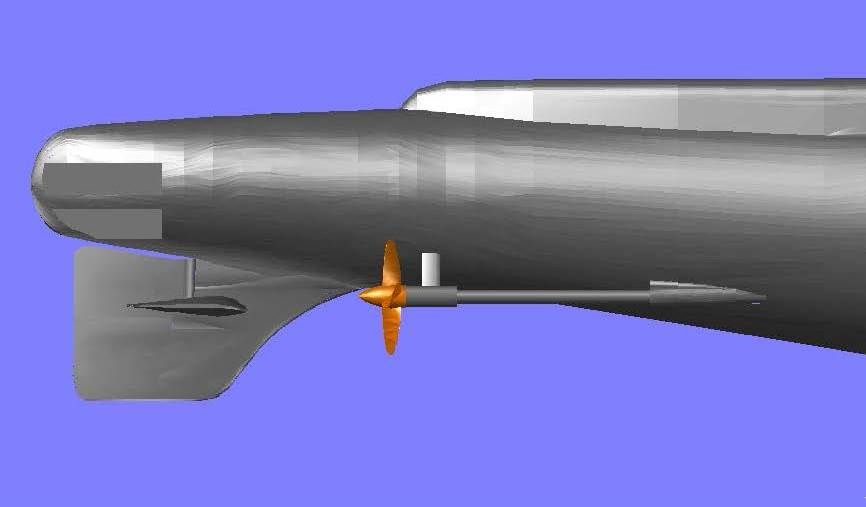
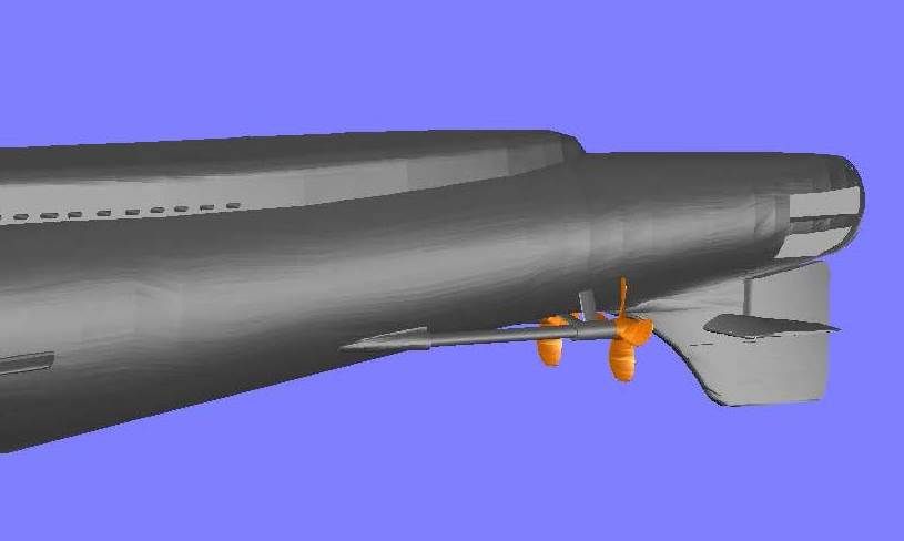
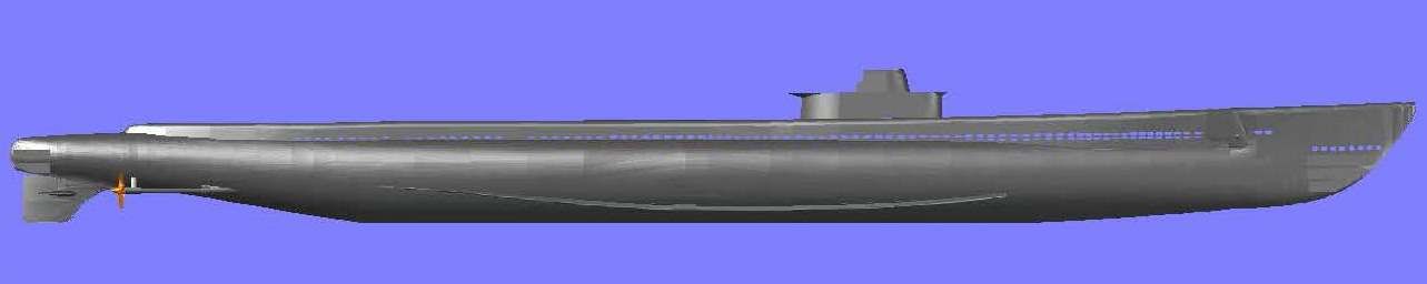
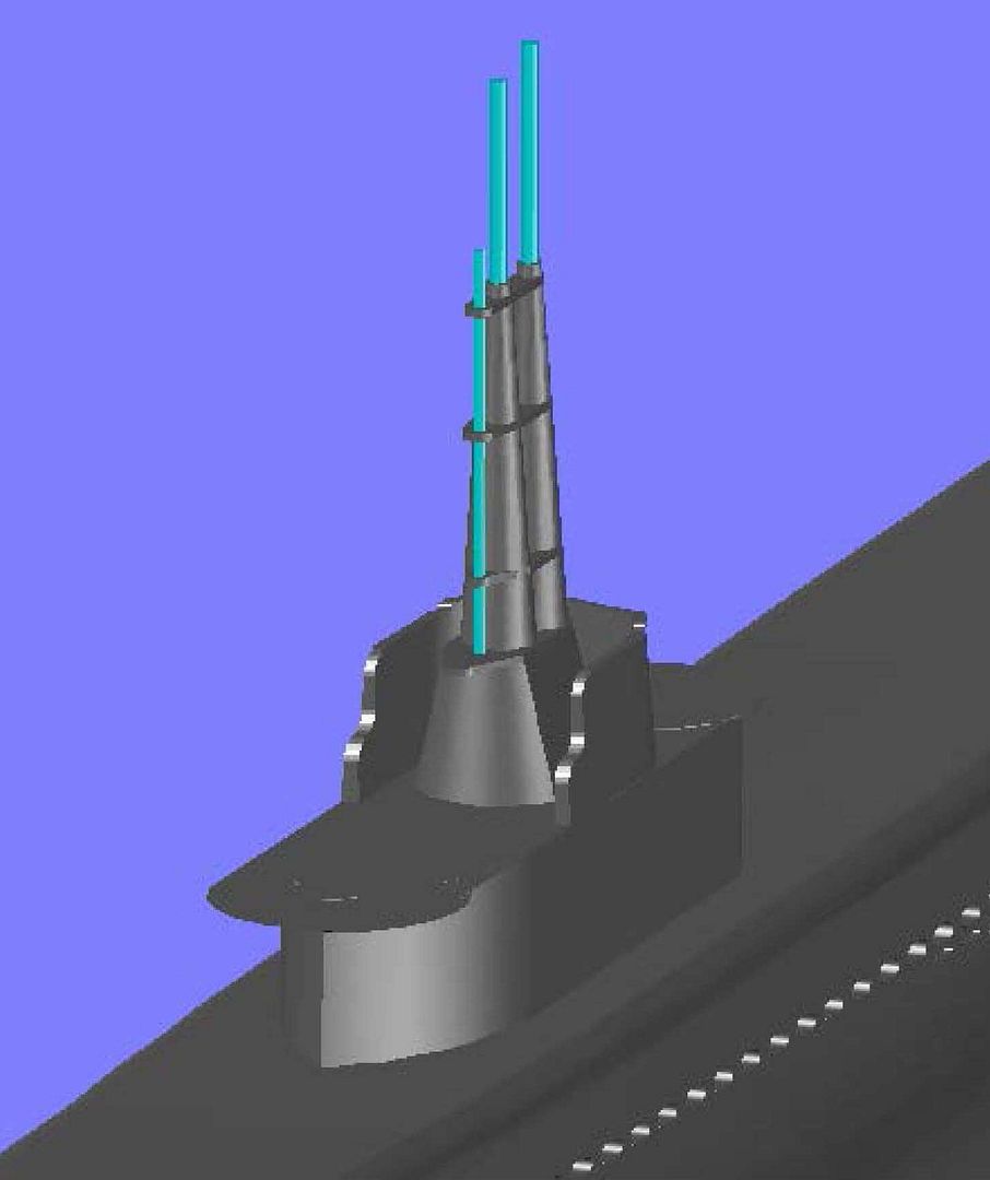
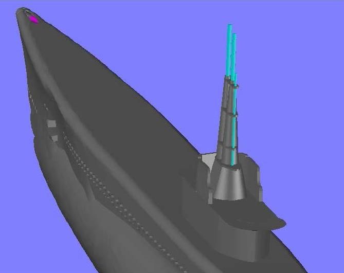
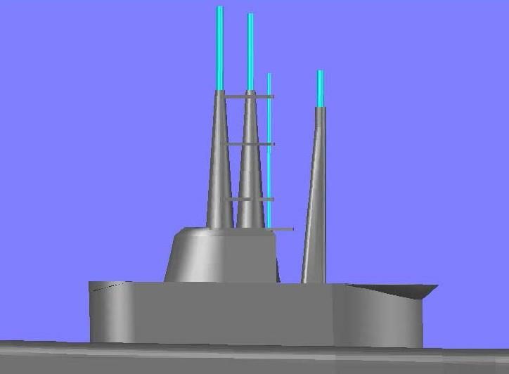
    The final step was to attach the sternpost to the hull, and recolor it. In the process, I experimented with colors and decided to switch to a more “silvery” color. I left the rudder red at this point because it will be a separate piece. In fact, with the SLA, I could build it in place, and still have it be moveable, although it may be too small for this option.


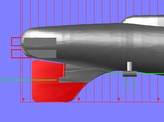
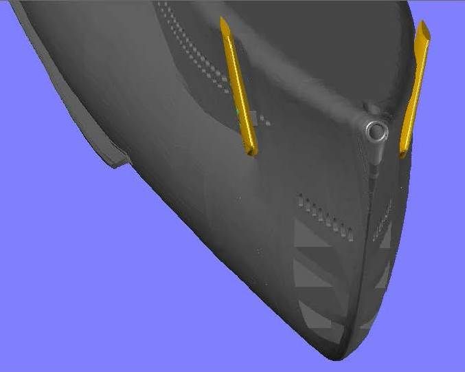
    Now, it’s on to the stern planes.

    Comment

    • rdutnell
      Junior Member
      • Nov 2012
      • 388

      #17
      Re: 1/144 Scale USS Batfish (SS310)

      UPDATE 7

      Good Morning All!

      I did the stern planes. Here’s the scoop.

      I started by importing the stern plane plan sheet into a new AutoCad file and scaling it, as always. I then traced (some of) the sections and copied them to the plan view.


      I then rotated the sections and lofted them, except for the end section, which I had to add more sections to in order to get the curved ends.


      I lofted these end sections and joined it to the rest of the plane.


      I then “drilled” a hole in the end in the usual manner, using the plans to locate and size the hole.


      To locate the plane correctly on the sternpost I copied the circle on the plan sheet…


      …And extruded it.


      I then copied it to the Batfish model and positioned it properly.


      I then copied the stern plane onto the Batfish drawing…


      …And rotated it 90 degrees.


      With it in the correct position I checked the radius of the shaft holes. The holes in the sternpost were larger.


      Since I don’t need the bulk for strength, I deleted the green cylinder, and subtracted the yelloe one from the sternpost.


      I then moved the plane into position and mirrored it.


      CHEERS!!!

      Comment

      • rdutnell
        Junior Member
        • Nov 2012
        • 388

        #18
        Re: 1/144 Scale USS Batfish (SS310)

        UPDATE 8

        Hey Guys!

        Well, I decided to try to redo the bow. This required using two new additional plan sheets, the “Bow Framing Sections A to 9 Incl.” sheet and the “Stem Casting & Fairlead” sheet. The latter was discussed earlier, and even though the quality isn’t very good, I finally deciphered it. I must say that this was the second most difficult part I have made to date, the hardest still being the Greenling screw. I didn’t get it right the first time, that’s for sure.

        To start I traced Frames 1, 0 and A from the “Bow Framing Sections A to 9 Incl.” sheet, after first bringing it into AutoCad and scaling it of course.


        I then copied them to the proper locations on the hull datum, rotated them and lofted them. This was the easy part.


        From here I switched to the “Stem Casting & Fairlead” sheet. Shown below are Frames A and B positioned correctly on the drawing.


        I started with Section G-G’, as may be seen below.


        I next started on Section C-C’, but as you can see the remaining sections only show the top part.


        At this point I copied and rotated the four sections to the side of the plan sheet.


        Section C-C’ was completed by estimating it’s position between existing sections and drawing a polyline. When half was completed, it was mirrored and joined to form the section.

        The remaining sections were created in a similar manner. In the image below, the blue sections are open. And the green sections are closed, with a hole drilled through them.


        The closed and open sections won’t loft properly. It’s like comparing apples to oranges, so I reasoned (partially correctly, that the end closed sections needed to be duplicated, but with small openings, to accommodate the transition.


        I did the open sections first…


        …Followed by the closed ones. The magenta lines are “Guides” for better lofting.


        I then extruded a circle along the axis provided on the plans…


        ...And subtracted it. The results were mixed. The aft end was good the forward end was not. I don’t know what I was thinking.


        The good news/bad news is that since my brain was on holiday, it took me a while to realize the idiocy of what I had done, so I traced the ends of the outer section (Section G-G’), revolved them 360 degrees, then rotated them between the ends, thinking that I would round off the end in this manner.


        It was at this point that I discovered the folly of my ways, and redid it. This required modifying Section G-G’ to make it closed and lofting to it from Section F-F’. I also closed the loop.


        Next I extruded the circle again, and created a tapered surface by lofting between Section G-G’ and a circle internal to the loop.


        I then extruded the circle and filleted the edge of the circle.


        This was better, but still not quite right.


        So, I tried yet again.


        This was looking better, but in the process of filleting the circle surface it occurred to me that maybe I could fillet the other edge of the yellow slice and do away with the loop all together. After some trial and error I discovered that a fillet radius of 0.18, gave the desired result.


        It looks a little rough at this scale, but it looks better on the ship.


        Out of curiosity, I extruded the circle once again along the axis provided in the plans.


        It’s a good thing I did, because you can see that there was a little extra cut.


        The last thing I did was drill the hole topside and join it to the rest of the ship.


        It’s not perfect by any means, as a result of me having to guesstimate the lower parts of the sections. I could probably improve it by trial and error, but that would be a very time consuming exercise, and if need be, a little sanding will correct it.

        Anyway, it was a lot of fun, even if it did take me about 12 hours to do. Now for the screw! That’s what she said!

        CHEERS!!!

        Comment

        • raalst
          Senior Member
          • Feb 2003
          • 1229

          #19
          Re: 1/144 Scale USS Batfish (SS310)

          very nice !
          3D modelling is another skill to learn for me. thanks to your posts I
          can learn how to attack complex shapes.

          I'm not sure what scale you want this printed in, but in general I found that
          sometimes I was fretting over little details, only to discover you could not find
          them back in the printed results.

          So as for your nose section, you could have built a closed nose, then substract the hole, and leave the
          sharp edges to the sandpaper ?
          Is there a reason such an approach is less effective (except for the fact that post processing, i.e. sanding is more work) ?

          Comment

          • rdutnell
            Junior Member
            • Nov 2012
            • 388

            #20
            Re: 1/144 Scale USS Batfish (SS310)

            UPDATE 9


            Thanks Ronald! I’m happy to hear that my posts could help you. As for the way I did it, the answer is twofold. The first is that I don’t really have much experience at this, so I don’t really know what I am doing, and am learning as I go. The second is that even though I plan to eventually scale it to 1/144 scale, I am doing the model at full scale, straight from the plans, and it is really two games for me, trying to build the full scale model as accurate as feasible, and if I can get it printed, building it. I therefore sometimes think about the full scale model without thinking about the 1/144 scale model.

            The way you suggested doing the bow is what my buddy said to do, and in hind sight, especially after I learned that you could fillet irregular surfaces, I should have done it that way. And who knows, I still may redo it. If I do I will do what you say.

            As for the build, I have had a productive weekend. I completed the screw this morning, to scale, even though I don’t think that it can be printed at the 1/144 scale I’m going to build (I hope). I don’t know if 1/144 scale Fleet Boat screws are available, but there aren’t any on FreeTime Hobbies site, so I am not hopeful. Like I said, this is two games, and the first is to build the ship full scale. When I scale it down and start dissecting it for printing, I will make adjustments as needed. Based on Greenling’s screw which was 0.01” thick, the thinnest point needs to be more than 0.02”(?) to print adequately. This would require redesigning the blade to thicken it, which would make it out of scale, and even then I don’t know if it will print right. Perhaps I should just look into getting a PE kit.

            Anyway, it was WAAAAY easier making the screws for Batfish than it was for Greenling. It’s amazing what a good set of plans will do. Here are the steps I took to do it.

            I started as usual, by copying the plans into AutoCad and scaling them. In this case I then had to copy it and rescale it, because the scale for the blades was not the same as for the hub.

            After doing this, I traced the hub using a polyline.


            I then revolved it 360 degrees.


            I then turned my attention to the blade sections and traced them using a combination of arcs and polylines.


            I then copied the blade sections to the correct position on the blade part of the drawing using the reference lines provided on each drawing for positioning.


            I then drew the radial lines of angular rotation.


            Each section was then rotated to align with its guideline…


            I copied the base section inside the hub, although this step turned out to not really be necessary.


            I then rotated the sections 90 degrees around their face axes.


            Viewed orthogonally, you can see the effect of these actions.


            At this point the sections were lofted together using guides drawn between the end points of the sections.


            Turning off the plans layer allows you to see the entire blade.


            The next step was to join the sections and copy the blade to the hub, again using the reference lines on the plans.


            At this point, I switched views and reference frames…


            …And rotate/copied the blade around the hub.


            I then recolored the hub and clipped some images of it.


            Note the shaft hole drilled in the end of the propeller. On the plans, the shaft tapers inside the propeller, but I didn’t taper it. Instead I used the largest diameter of 0.8’. Even that is smaller than the shaft support holes that are 1.06’. This doesn’t really matter though, because these diameters will be adjusted when I scale it.


            With the screw completed, I copied and pasted it to the Batfish model, at the end of the shaft support, and copied it again to the other side.


            I then added shafts, although, like the screw, they aren’t actually part of the ship. It looks better with them on.


            I don’t know when I will get to play with it again, perhaps this evening, but if not it will be next weekend at least. When I do, I will have to take a look at the “Bridge Arrgt.” drawing and see what damage I can do.

            CHEERS!!!

            Comment

            • JWLaRue
              Managing Editor, SubCommittee Report
              • Aug 1994
              • 4281

              #21
              Re: 1/144 Scale USS Batfish (SS310)

              Russ,

              Very quick work!

              I have a question: when doing 3D modeling with a surface applied, how does one 'smooth' out the surface to deal with the discrepancies of tracing the lines from scanned blueprints?

              -Jeff
              Rohr 1.....Los!

              Comment

              • rdutnell
                Junior Member
                • Nov 2012
                • 388

                #22
                Re: 1/144 Scale USS Batfish (SS310)

                Hi Jeff,

                I’m not sure exactly what you are asking, but obviously the quality of the tracing is dependent on the quality of the plans being traced. If they are decent quality prints, then you can zoom in so that the lines are pixel squares and you can use very short distances connecting the center of the darkest squares. This makes for really small segments, but can take a lot of time. If the line zigzags, due to poor production or reproduction, you can use an arc, where you specify the beginning, middle and ending, to smooth it out. Of course, I would do that before I lofted it, or extruded it, to make a solid or surface. Also, when lofting between multiple sections, there are several options on how to do that, one of which is smoothing. The problem is that this can sometimes produce strange results. Using a path or guides can help in these cases.

                I hope this answers your question.

                Russ

                Comment

                • JWLaRue
                  Managing Editor, SubCommittee Report
                  • Aug 1994
                  • 4281

                  #23
                  Re: 1/144 Scale USS Batfish (SS310)

                  Hi Russ,

                  ...sort of. If you look at the close-ups of the hull, you can see where the surface does not transition smoothly from one frame to the next. It's that smoothing out of that I'm curious about.

                  -Jeff
                  Rohr 1.....Los!

                  Comment

                  • rdutnell
                    Junior Member
                    • Nov 2012
                    • 388

                    #24
                    Re: 1/144 Scale USS Batfish (SS310)

                    Hi again Jeff,

                    The quick answer to that is poor AutoCad skills and application. AutoCad has a lot of features and settings that I don’t know how to use effectively, so I generally just use the default settings. There are many ways to loft shapes to form a surface or a solid and I don’t know many of them. I’ve only recently discovered that if you use guides, you get a better surface. I think probably the best way to do it would be to loft it as one unit and experiment with the smoothing features. Another way I guess would be to add extra sections between existing ones to better define the surface. But who knows, there could be a Command in AutoCad that will smooth surfaces after they are made. I don’t know. As it is, I think some sanding may be on order, if I ever get to actually make it.

                    CHEERS!!!

                    Comment

                    • scott t
                      Member
                      • Feb 2003
                      • 880

                      #25
                      Re: 1/144 Scale USS Batfish (SS310)

                      Great job Russ on both prop and bow fairlead.
                      I believe on the prop you will need to mirror one as there is a left hand and a right hand props.
                      Maybe someone who knows the way they turn can tell you which shape is right for which side.

                      Scott T

                      Comment

                      • rdutnell
                        Junior Member
                        • Nov 2012
                        • 388

                        #26
                        Re: 1/144 Scale USS Batfish (SS310)

                        Thanks Scott!

                        I did not know that, although it makes sense in order to counteract the torque created by the rotational forces. It just goes to show that you learn something new every day.

                        If I had read the General Notes on the plans, I would have known this. Item 1 says, “Looking forward starboard propeller shall turn right-hand (clockwise) and port propeller left-hand (counterclockwise) when driving the vessel ahead.”

                        The drawing is the right-hand screw so I need to mirror it to the port side.

                        THANKS FOR THE HEADS UP!

                        Comment

                        • rdutnell
                          Junior Member
                          • Nov 2012
                          • 388

                          #27
                          Re: 1/144 Scale USS Batfish (SS310)

                          Oh man Scott,

                          I am so glad you said something, because when I started looking at it more closely, I discovered that I had actually made a left screw and not a right screw. I’m not sure how this happened, but it just meant that I deleted the starboard side screw and mirrored the port side. I’m going to have to figure out what happened later when I get the time.


                          Thanks again!

                          Russ

                          Comment

                          • rdutnell
                            Junior Member
                            • Nov 2012
                            • 388

                            #28
                            Re: 1/144 Scale USS Batfish (SS310)

                            UPDATE 10

                            Well Guys, I am officially addicted! I have a lot of other things I should be doing, but I can’t seem to pull myself away from this model. I woke up early, so I could play with it for a couple of hours before starting on the list of things I had planned to do today. A couple of hours turned into six.

                            Anyway, I started on the “Bridge Arrgt” drawing and made good progress. The pictures provided by Tom (AKA salmon) on his photobucket site (http://s1089.beta.photobucket.com/user/ ... h%20SS-310) and some e-mailed to me by Scott helped enormously (Thanks Guys!), and I soon discovered significant differences between Pampanito and Batfish. I can’t say that I was all that surprised, as I was adequately forewarned by Tom D.

                            I started, as usual, by importing the drawing and scaling it to size. The first thing I did after that was trace the forward part of the conning tower(?) at the deck level, and the periscopes from the plan view.


                            I then traced the forward part of the top of the conning tower from the plan view at line C-C’…


                            …And copied it to the plan view.


                            Next, I switched to the side view, copied the periscope masts circles to the correct locations, rotated them, and extruded them.


                            I then followed the same procedure for the radar mast.


                            I next switched my focus to the platform at the top of the conning tower.


                            At this point, I decided to extend the masts down to the deck.


                            I did the conning tower next, and this is where the photographs really came in handy, as Batfish’s is a lot different than the plans.


                            I hollowed out the conning tower using the shell command and setting the thickness so that when scaled to 1/144 it will be 1/16” thick.


                            The middle bracket was next…


                            …Followed by the top bracket and the radar mast bushing(?) and…


                            …Then the bottom bracket. The thickness of the platform and brackets will be slightly over 0.2” thick at 1/144 scale.


                            At this point I started thinking about the model, so I copied the solids to the side to make two parts out of it. I joined the platform and brackets to the periscope masts, and joined the lower periscope masts to the conning tower.


                            I also drilled out the holes for the radar and periscope shafts.


                            I then prepared to make the attachment points for the two parts by lofting circle into both parts.


                            I added the posts to the bottom piece and subtracted them from the top piece.


                            The lower part needed support, so I added a support strip to the base and drilled out holed for connecting it to the hull.


                            With the structure completed, I added cylinders to represent the periscopes and radar mast, although they are not connected.


                            The next step was to copy and paste it to the Batfish model in the correct location.


                            The last step was to add connection posts to the deck for attaching the assembly.


                            Now, I have to get some work done before I start on the aft radio(?) tower, that I will have to rely on pictures to do, because I don’t have plans for it.

                            CHEERS!!!

                            Comment

                            • rdutnell
                              Junior Member
                              • Nov 2012
                              • 388

                              #29
                              Re: 1/144 Scale USS Batfish (SS310)

                              UPDATE 11

                              O.K., I got done what I absolutely had to get done, checked my e-mail, and to my delight Tom D. had sent me a plan sketch for the SD Mast.


                              So, I imported it into AutoCad and using the longest available dimension, 16’-6”, I scaled it to size, and since the drawing was tilted a little, I rotated so that the mast was vertical on the front edge. I then made the base by drawing a 28” square and filleting the corners at 0.5’. You may notice that my base is slightly smaller than the one on the drawing, but I know that it is 2.3333’, so I went with it, instead of resizing it to match the drawing. For the top part, I considered using a smaller circle, since my base was smaller, but decided not to, and just sized my circle to match the drawing. I then copied them to the correct locations on the plan view, and rotated them 90 degrees.


                              I then lofted the mast and the top shaft.


                              At this point I prepared the piece for mounting to the deck by adding a post to the bottom.


                              With the easy part accomplished, I turned to alignment. Without plans showing where the mast actually goes, and since I haven’t yet had the opportunity to go see Batfish and take measurements, I resorted to the pictures on Tom’s photobucket page. The best picture I found for this purpose is a patchwork of various photos Tom put together, as shown below. NICE WORK TOM!


                              This proved to be more difficult than I thought it would be, and studying the photos revealed some definite design changes between the two ships, besides the mast arrangement. The first thing I noticed was that the aft end of the fairweather on Batfish goes straight down, and does not have the jog that Pampanito has. The next thing I noticed was that the ends of the bridge platforms are different. On the plans I have, both ends have sloped support structures under the ends. Batfish has no such structure on the forward end and a differently sloped structure on the aft end. Comparing the image below with Tom’s excellent collage, you can see what I am talking about.


                              If you think adding features to the model is complicated, removing them can be even more difficult. In this case, it wasn’t too difficult. I chopped the fairweather off by drawing a rectangle extending from the rounded corner at the top of the fairweather down to the deck, lofted it, and subtracted it. Cutting off the platforms was a little more difficult but involved a similar process, except the extruded shape was created by drawing a polyline following the base of the bridge deck then extending out forward and to the sides. Unfortunately, I didn’t clip any images of this process. Nor did I clip any images of building the new platform aft, which required first drawing the cross section profile of the platform, using Tom’s photo, extruding it along an ellipse with axes on the end of the platform and the side of the bridge bulkhead, and joining it the the rest of the model..

                              In the image below, you can see these modifications as well as my first attempt at positioning the SD mast. In Tom’s photo, it appears that the forward edge of the SD mast is almost directly under the aft end of the platform extending aft of the number 2 periscope mast. However, when I position it in this location, it appears to be too far forward.


                              I moved it back a little, and I think it looks better, but it seems that the bridge (if I’m using the term correctly) extends too far aft. I know, in large part, thanks to Tom D, that the fairwether and mast arrangements changed considerably from ship to ship. Is it possible that the bridge was shortened as well? I wouldn’t think so because that would be a major undertaking, but I don’t know.


                              In any case, I am not going to finalize the SD mast location until I get some more information. I might have to make a special trip to Muskogee and go to the museum with a tape measure.


                              CHEERS!

                              Comment

                              • scott t
                                Member
                                • Feb 2003
                                • 880

                                #30
                                Re: 1/144 Scale USS Batfish (SS310)

                                I think you could have left the forward deck side walls as the drawing if
                                you wanted to as I think the Batfish had both before modifications were made.


                                Comment

                                Working...