
Re: 1/144 Scale USS Batfish (SS310)
UPDATE 23
GREAT STUFF TOM D! I appreciate today's lesson.
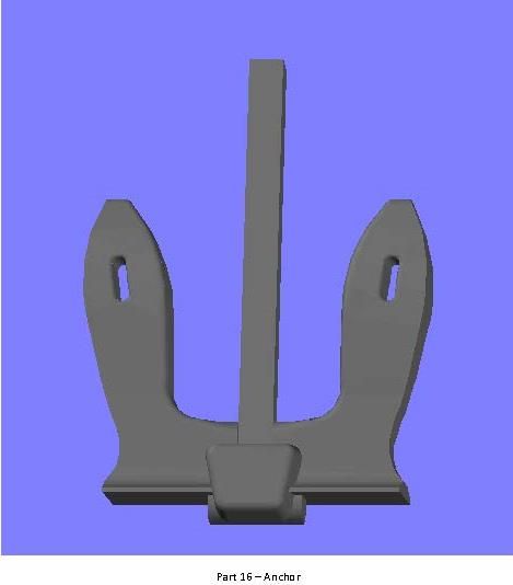
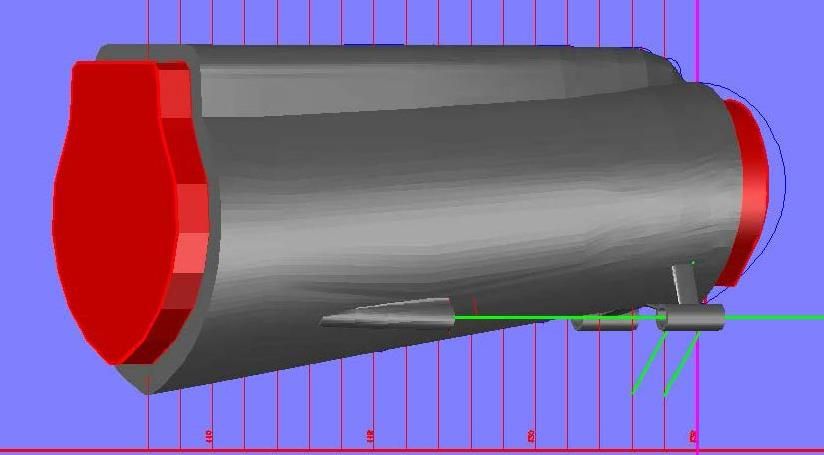
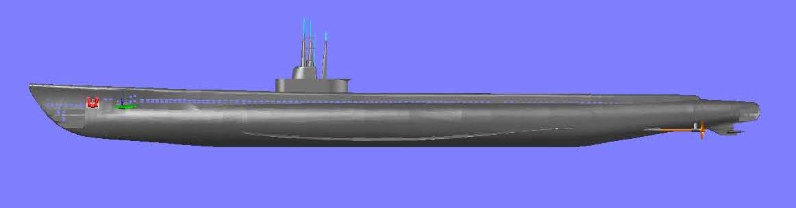
Fixing my blunder with the starboard side anchor was, easy, as I thought it would be. It was simply a matter of slicing, copying, pasting, and rejoining.
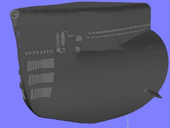
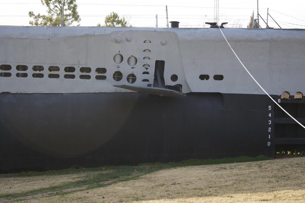
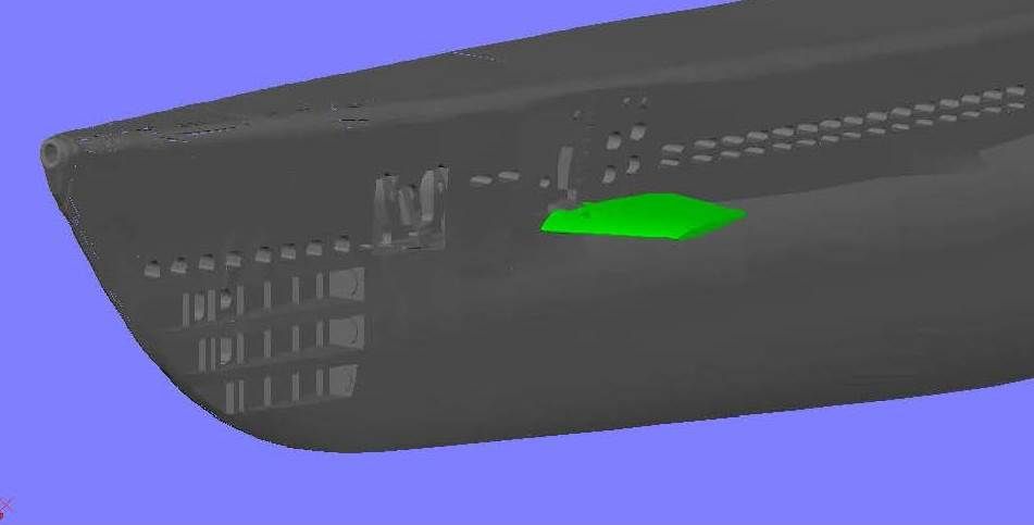
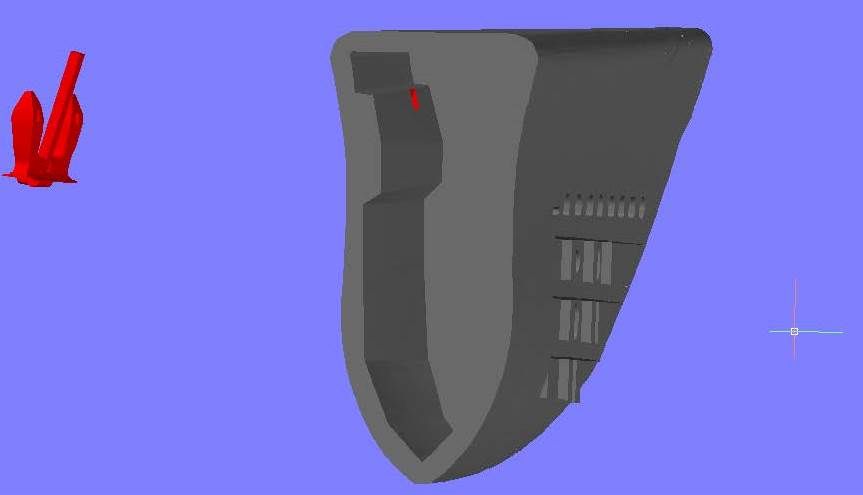
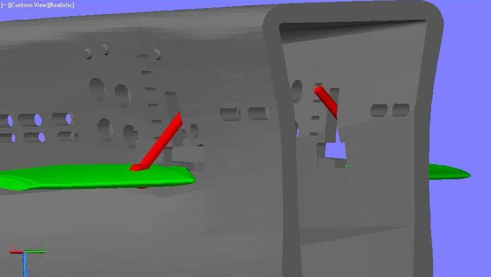
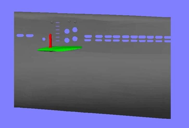
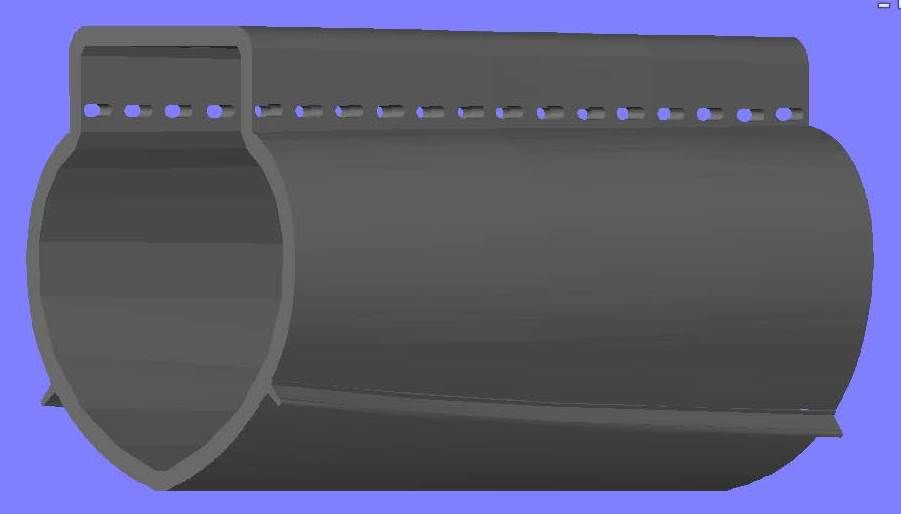
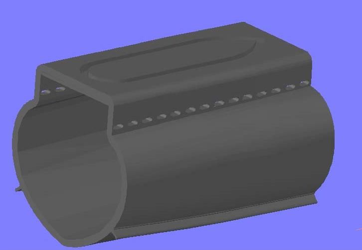
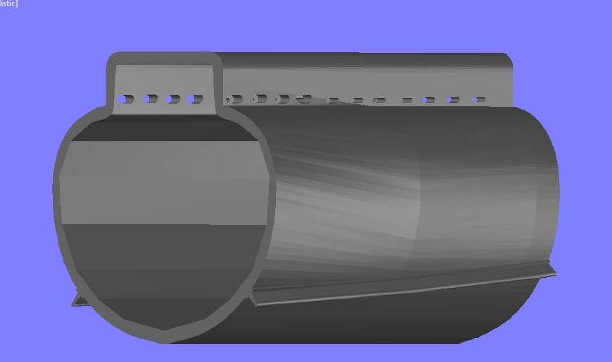
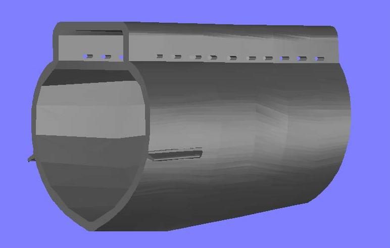
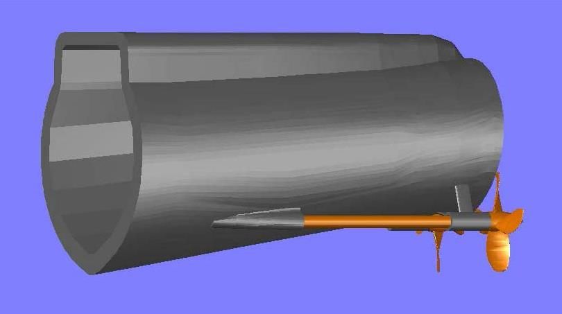
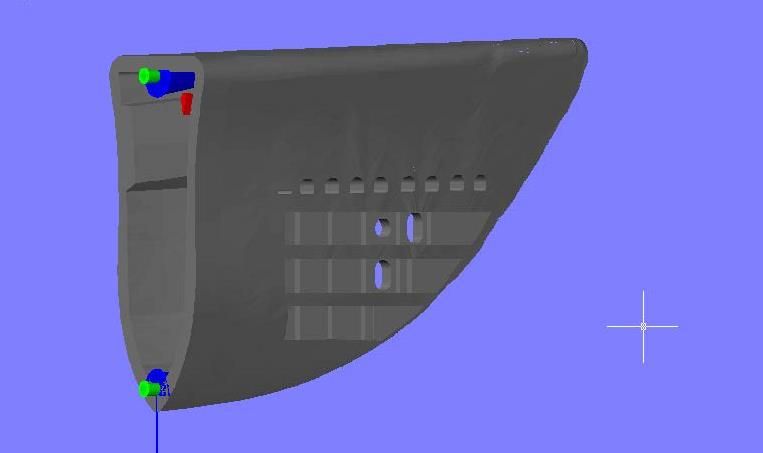
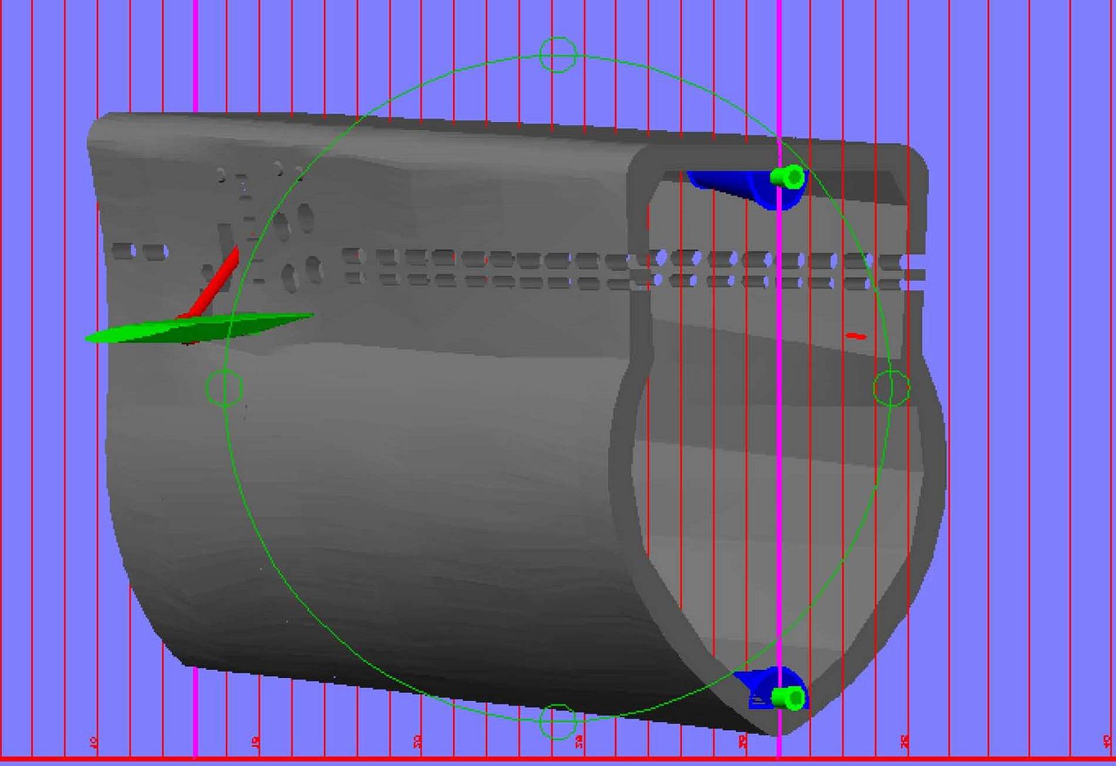
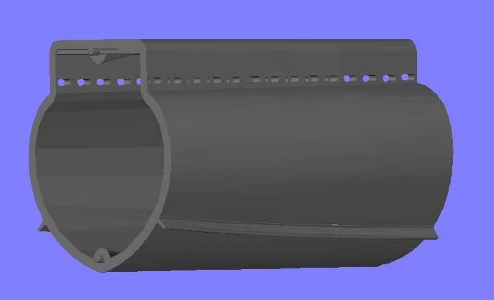
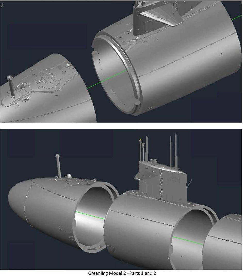
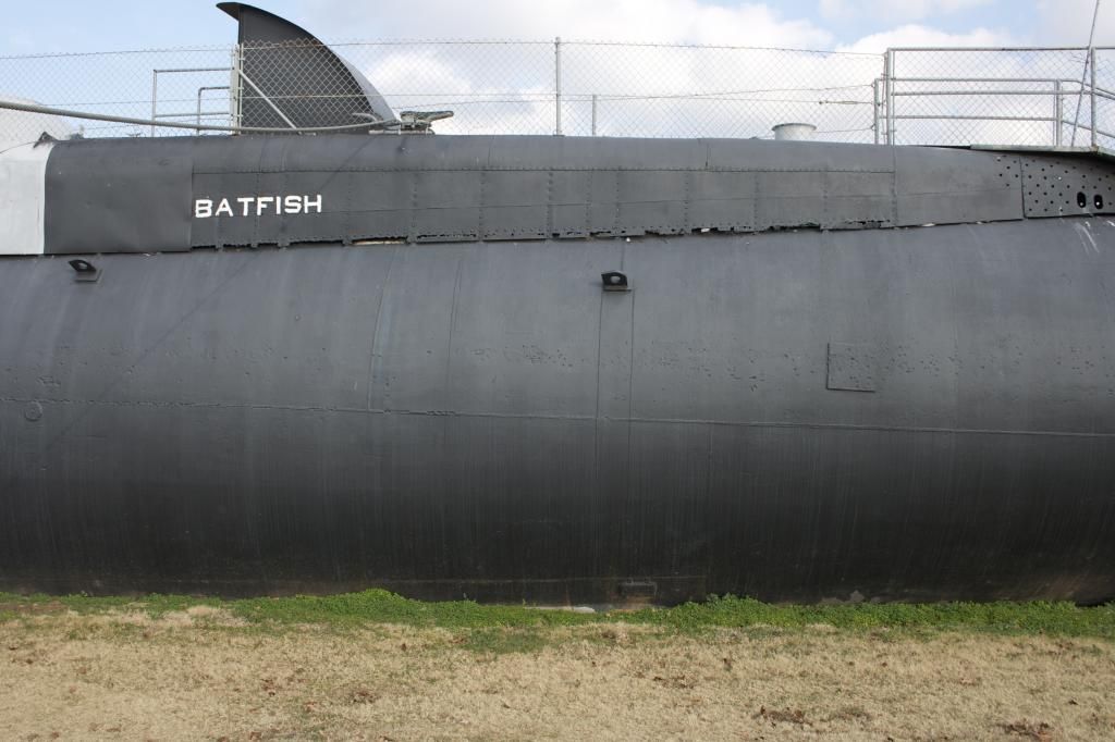
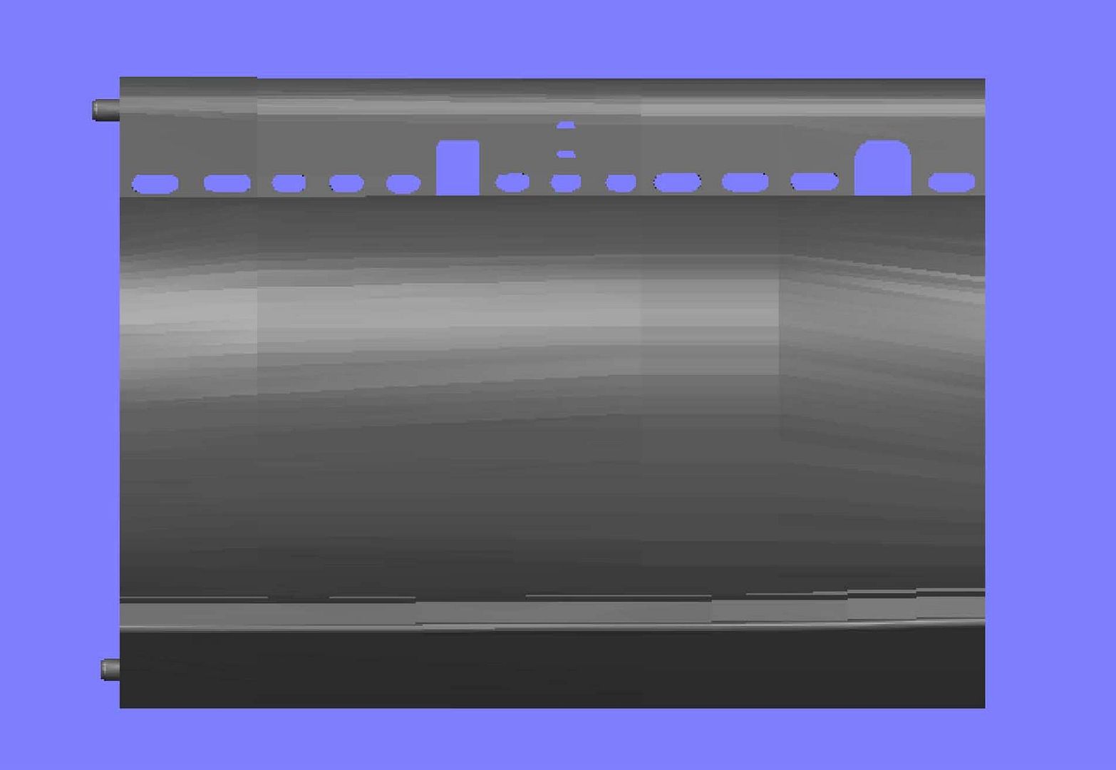
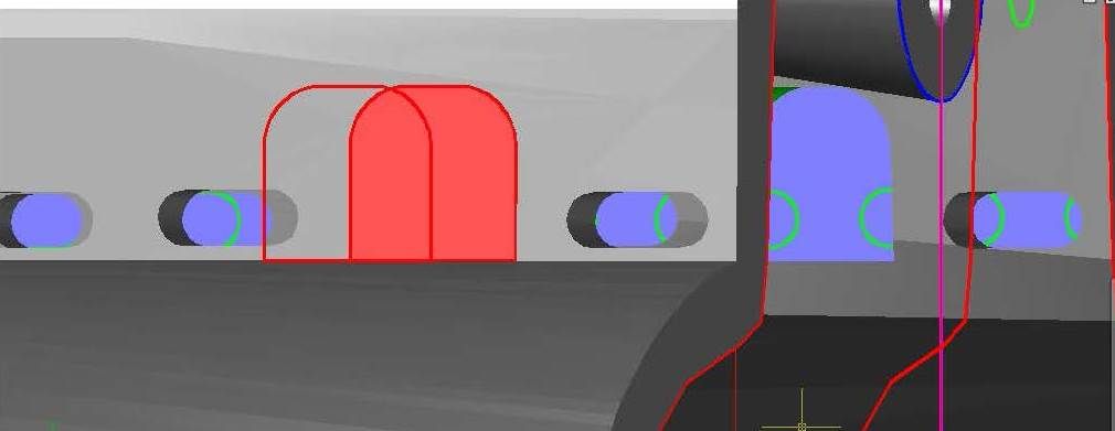
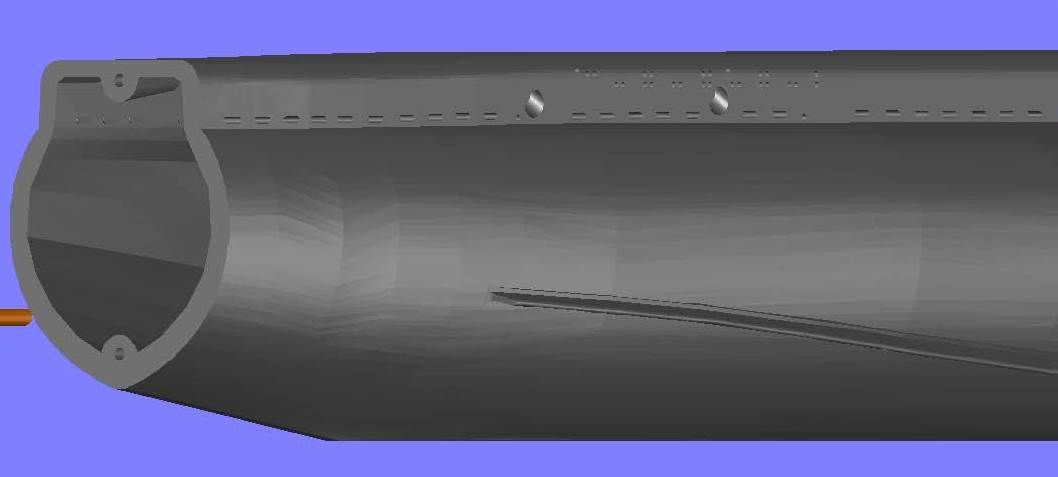
After I completed that, I decided to do the detailing on the forward torpedo tubes. Using pictures for the design, I started with one of the oval holes.


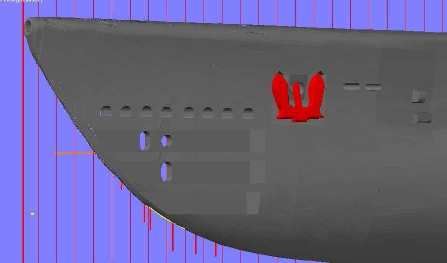
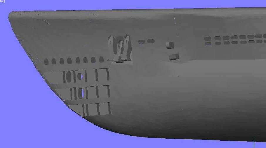
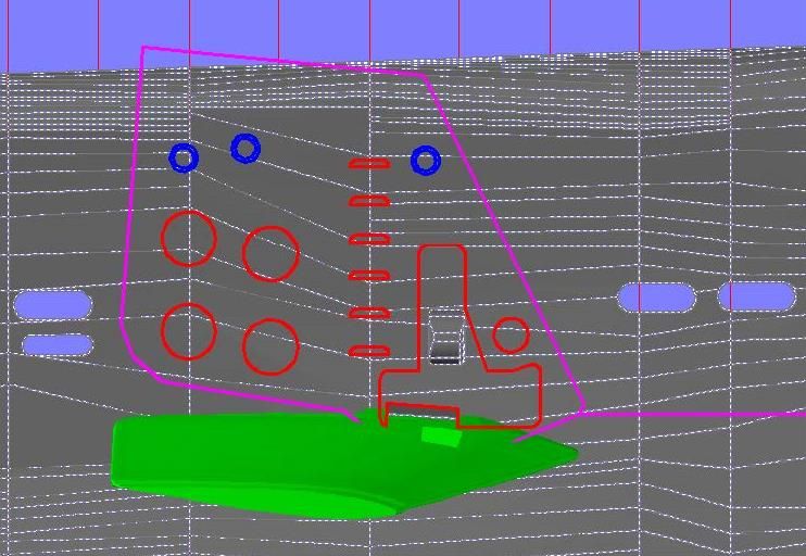
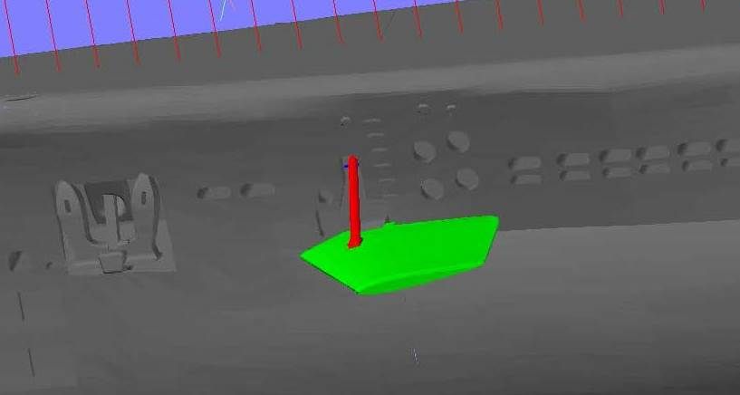
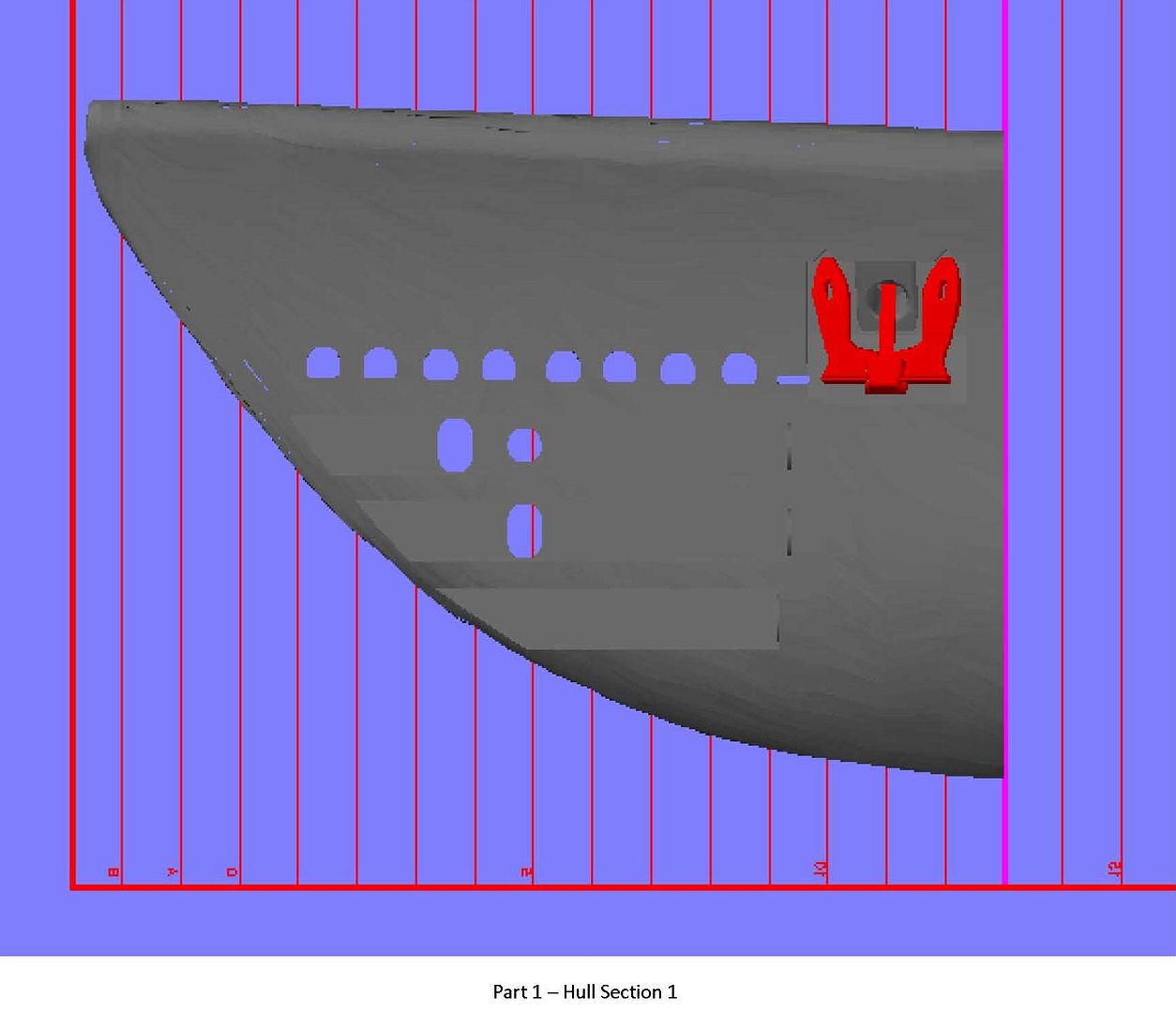
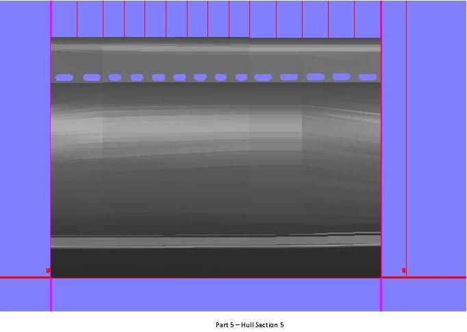
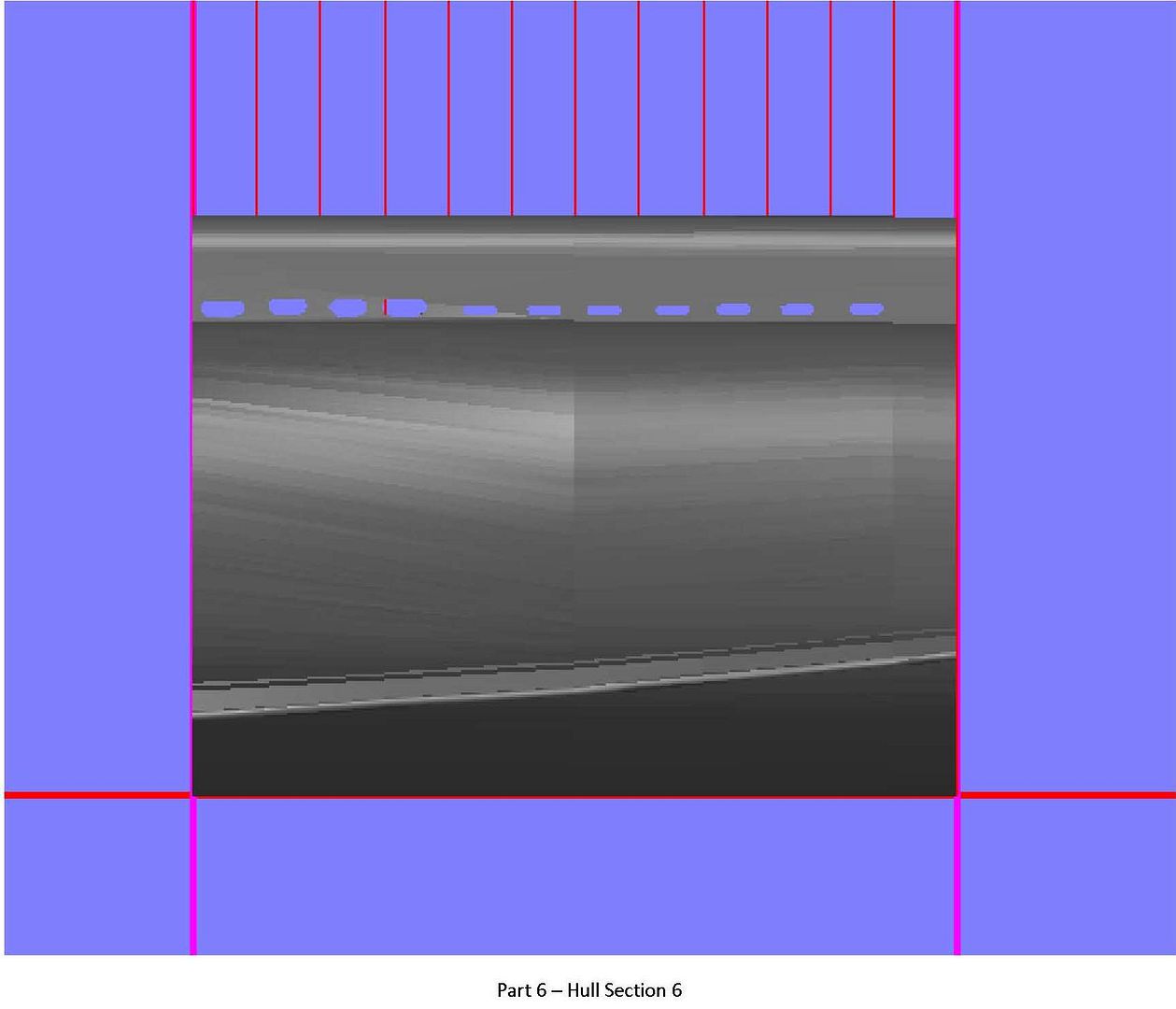
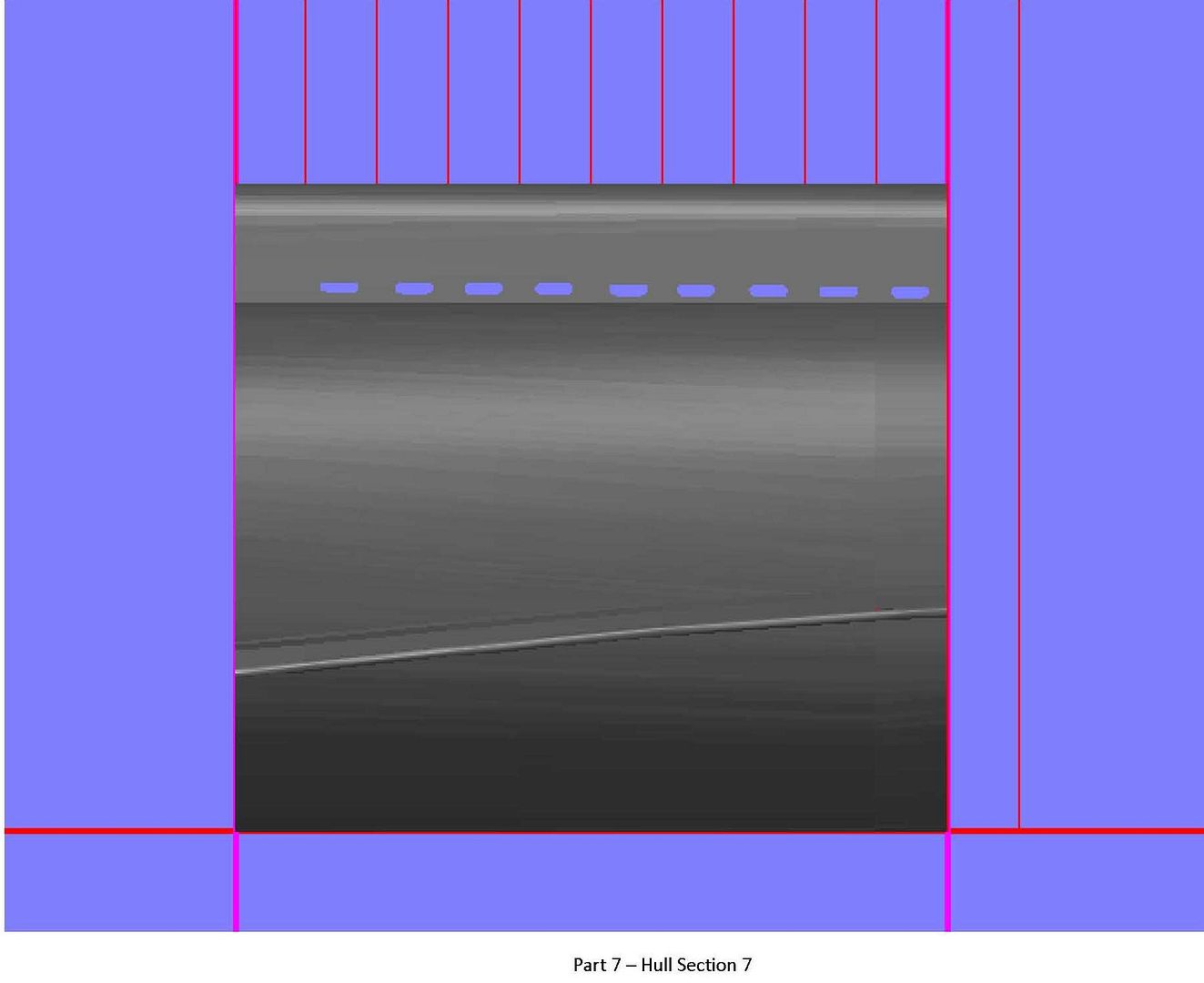
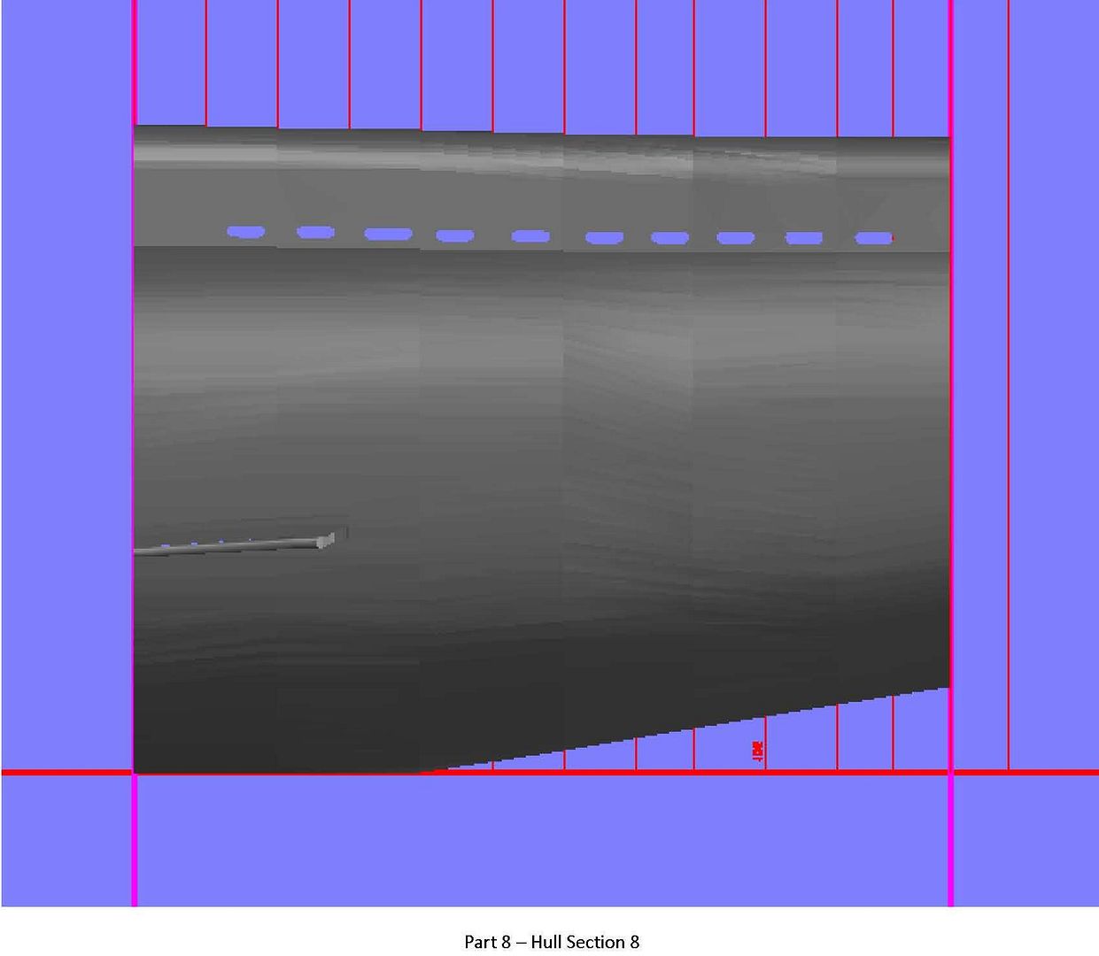
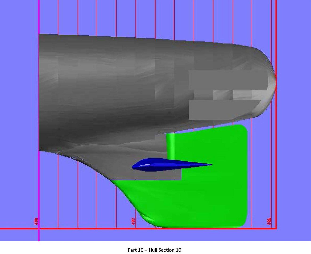
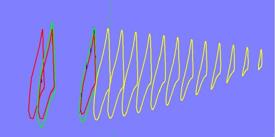
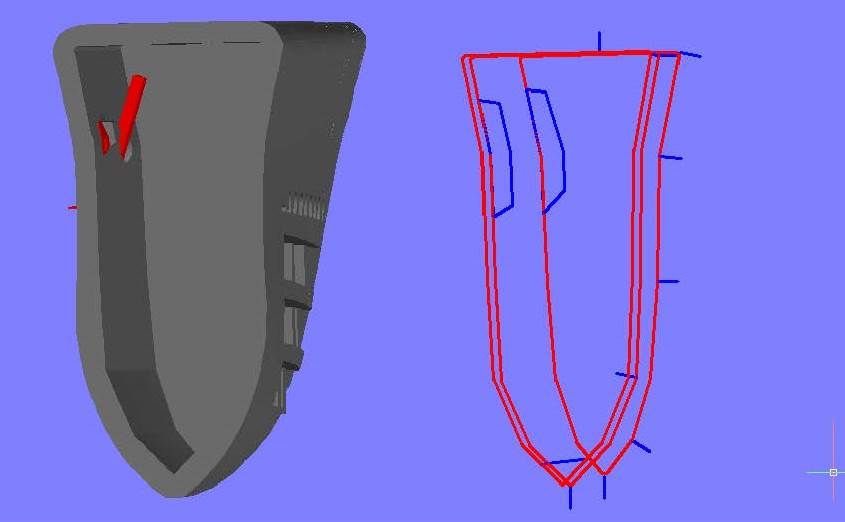
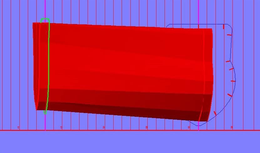
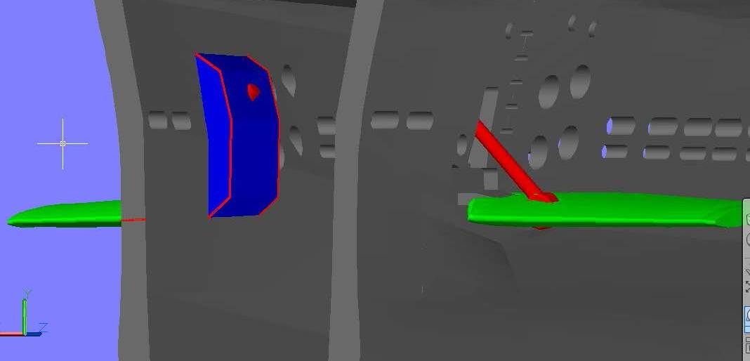
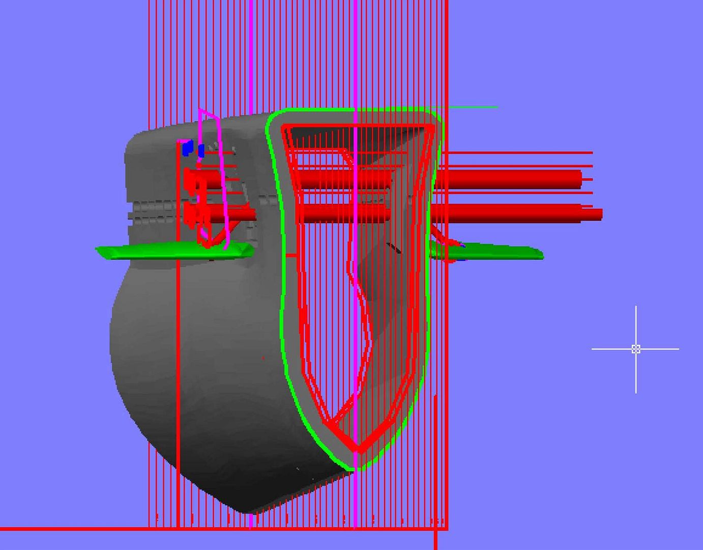
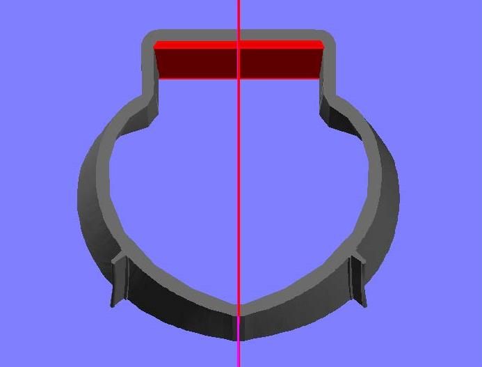
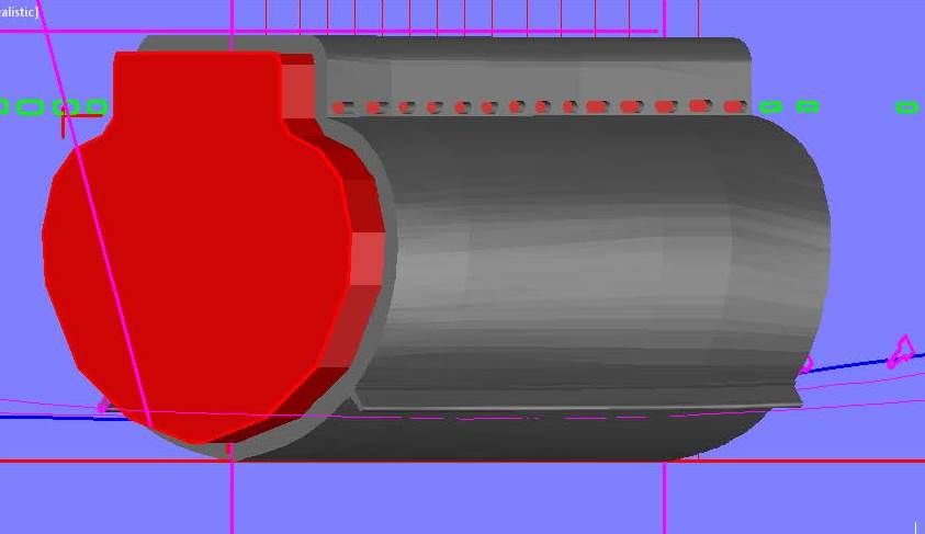
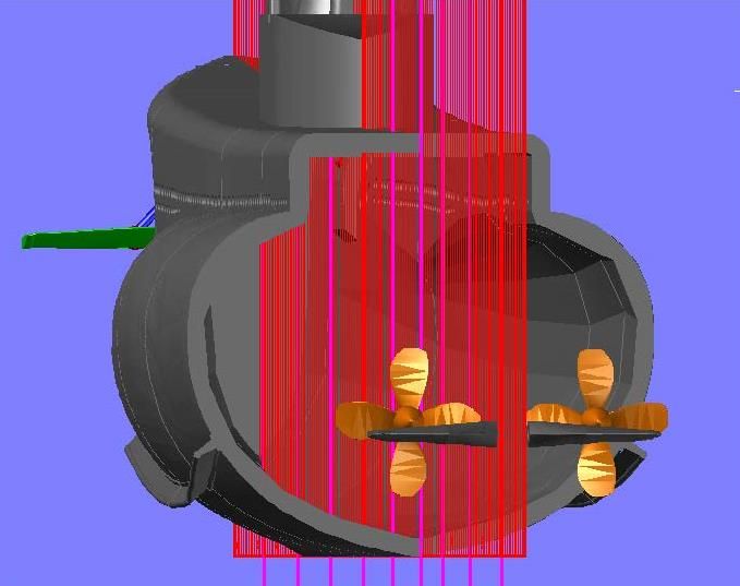
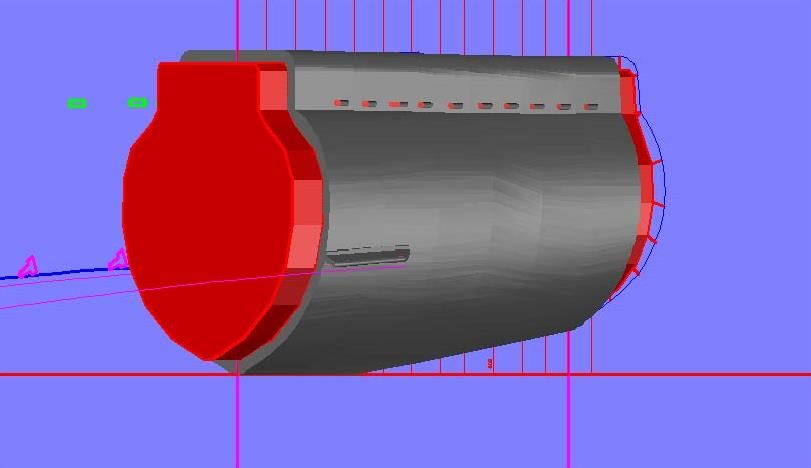
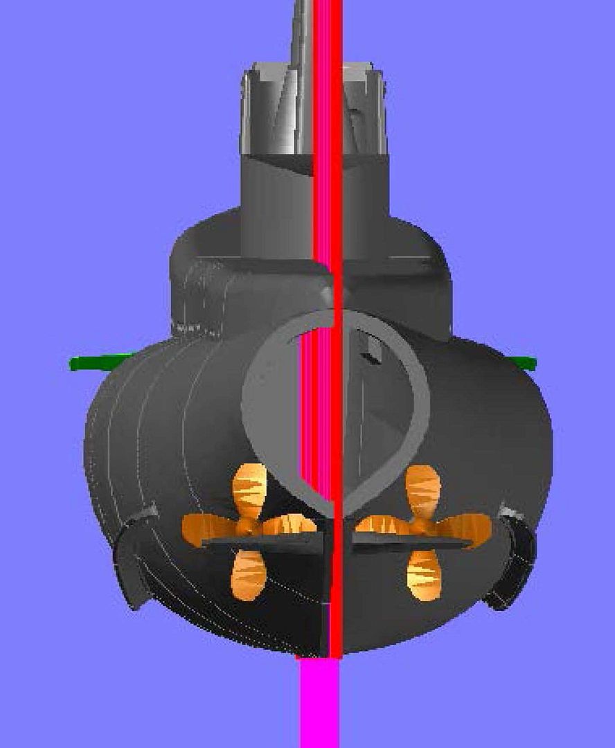
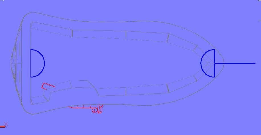
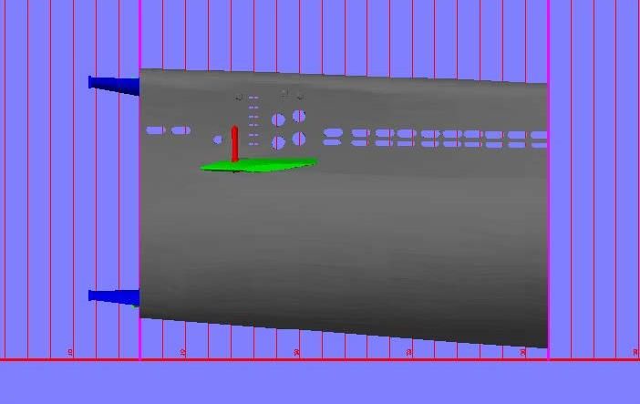
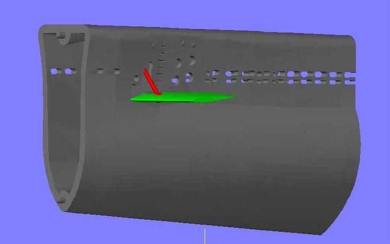
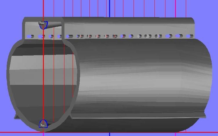
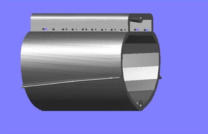
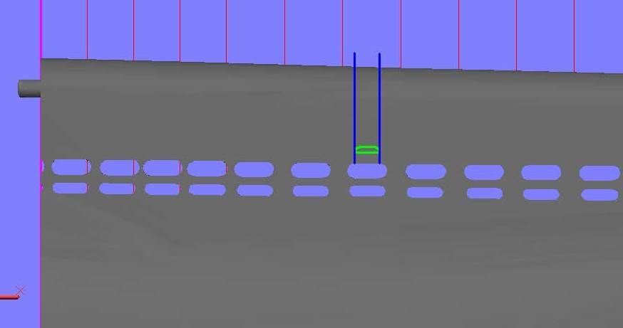
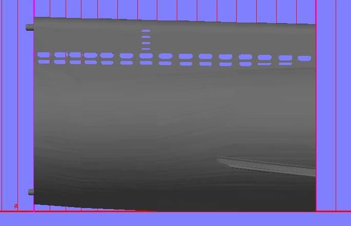
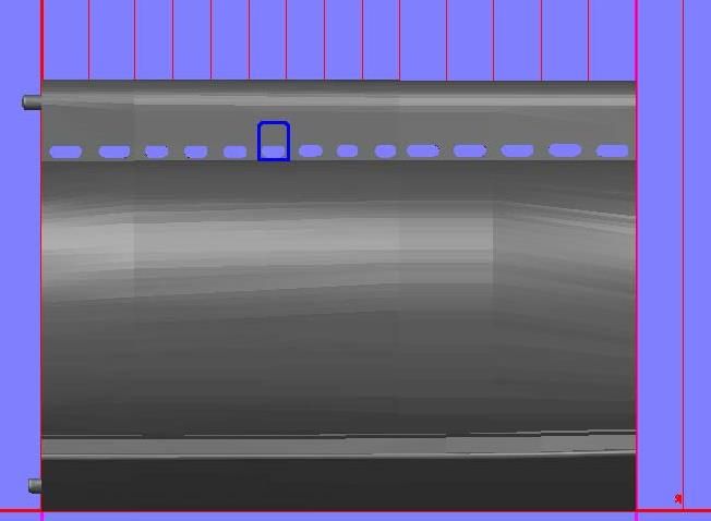
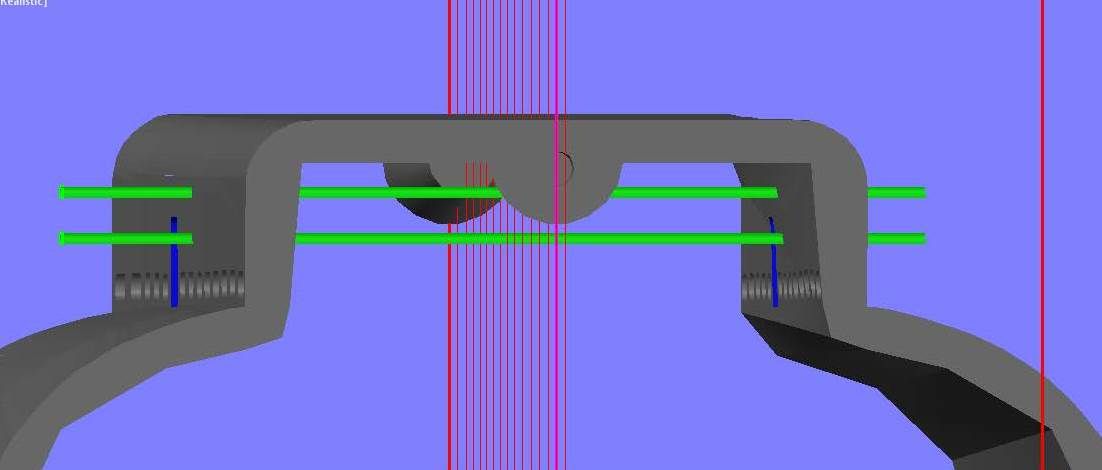
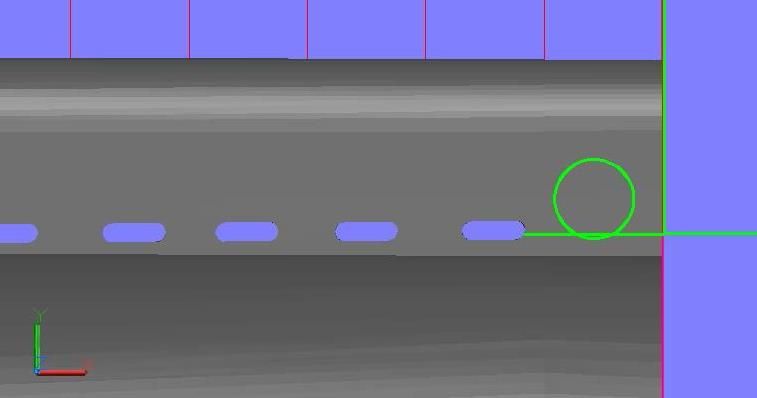
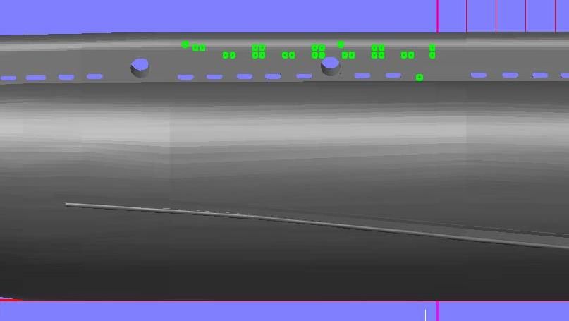
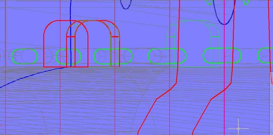
At this point I started drawing the guide lines for the vertical support structures visible inside the “tubesâ€. It wasn’t looking right to me, and previously I had suspected that the forward limber holes may be a bit low, so I went to the plan sheet drawing and copied both the limber holes and the torpedo tube construction lines to the hull1 drawing. As you can see in the image below, my suspicions were correct. They are too low.
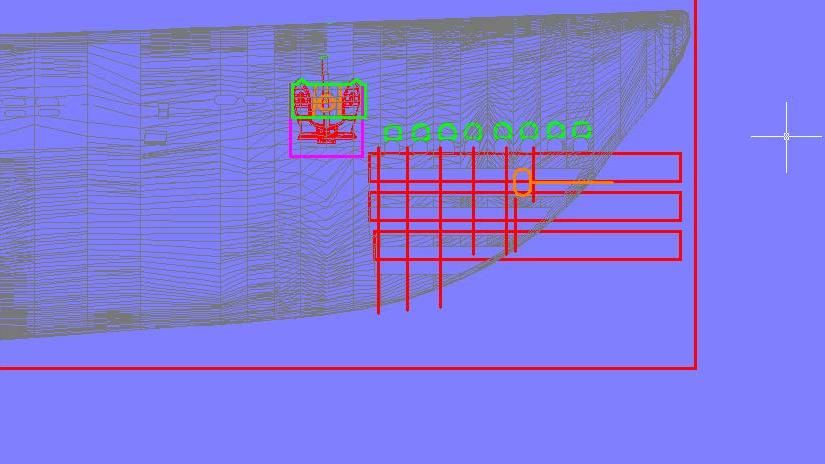
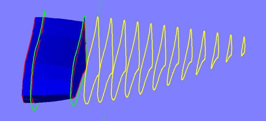
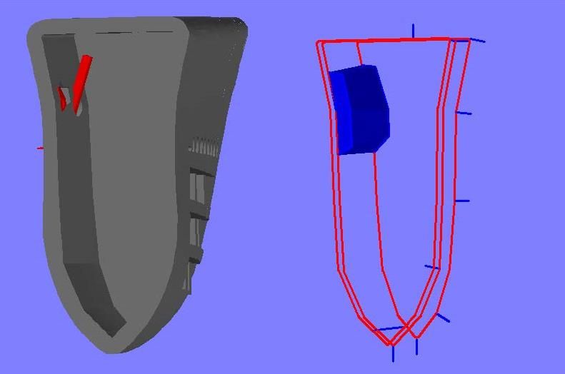
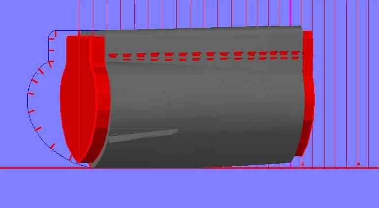
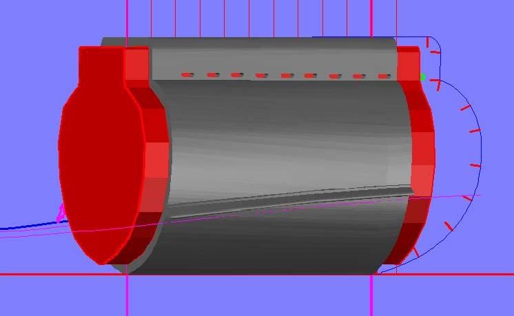
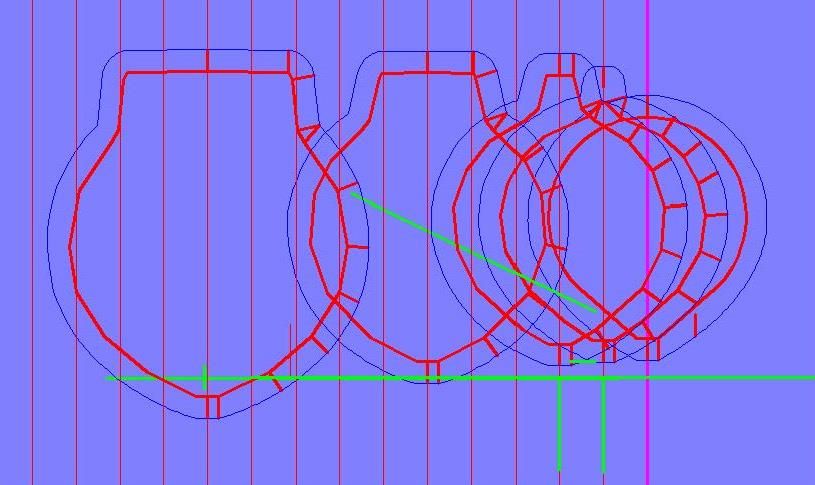
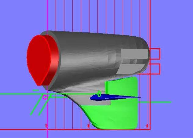
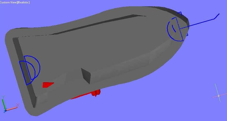
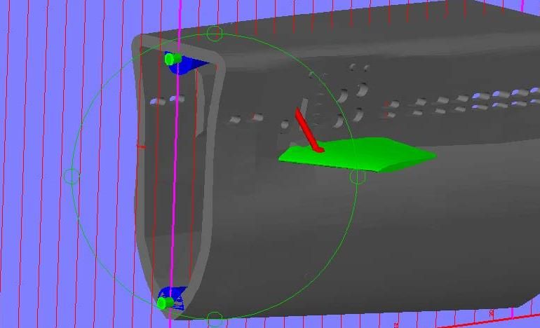
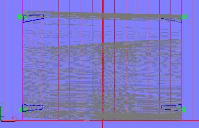
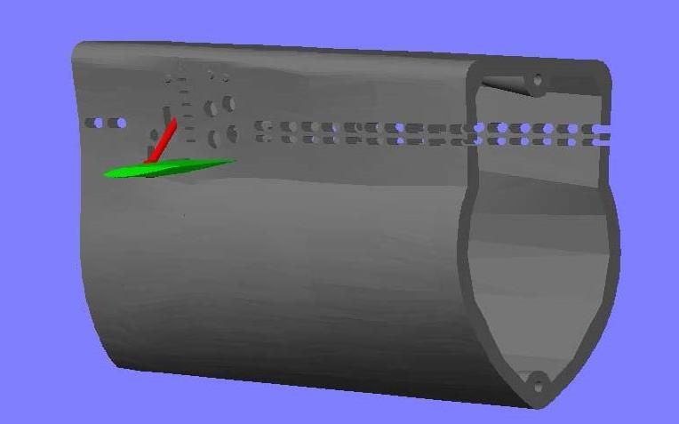
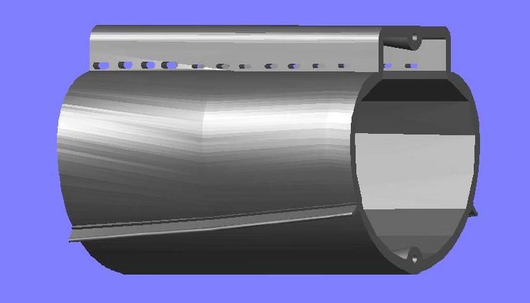
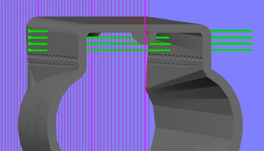
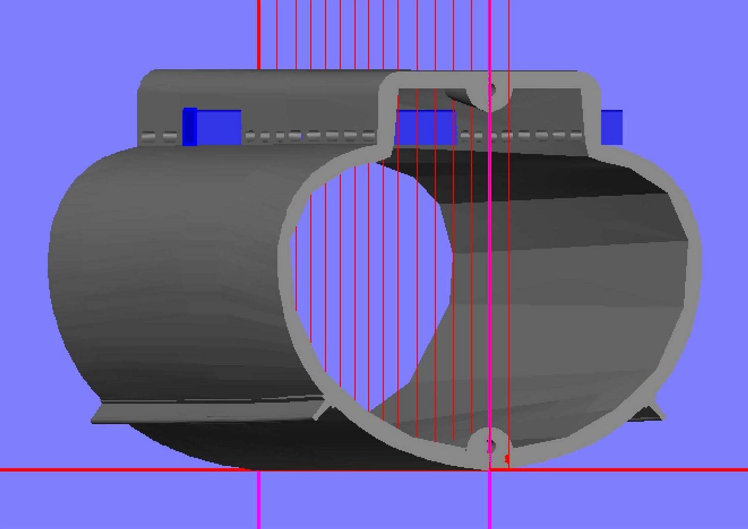
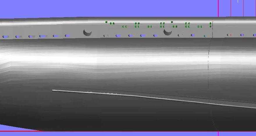
Fixing this required redoing the front end, so I sliced the hull from Frame 10 to Frame B, copied the sections to the appropriate frames and rotated them.
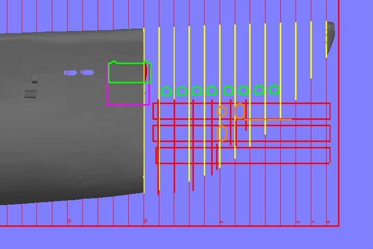
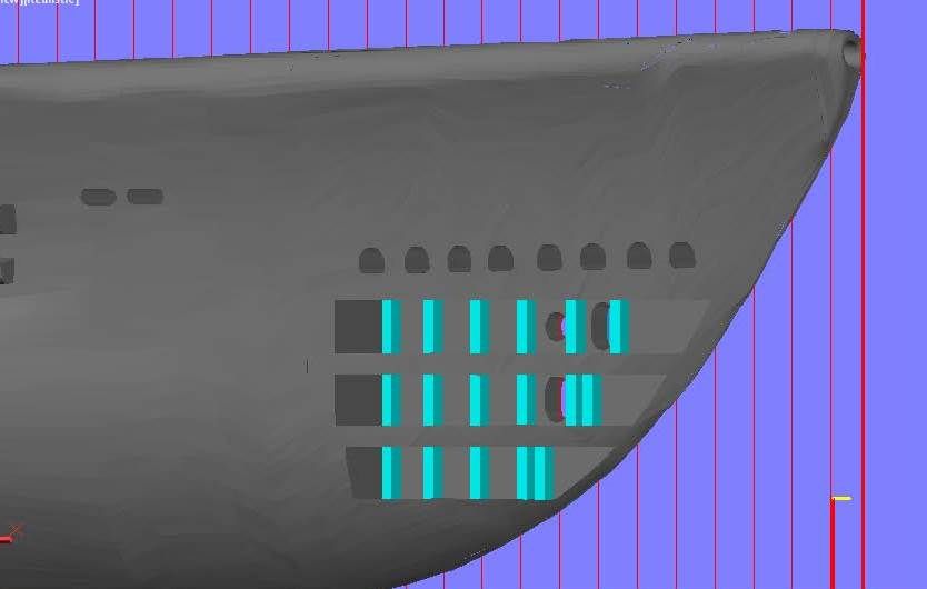
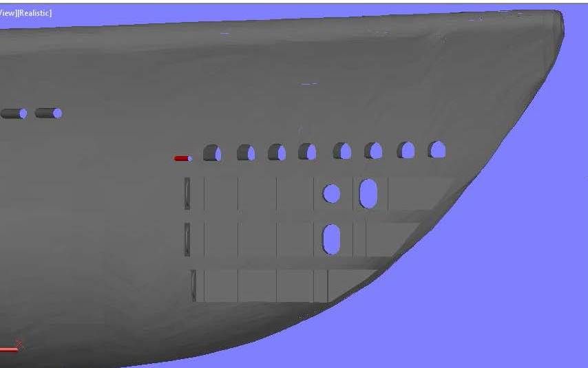
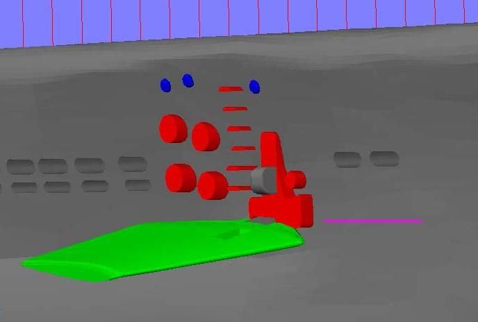
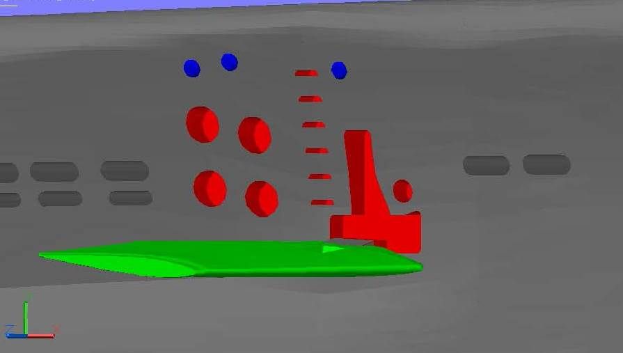
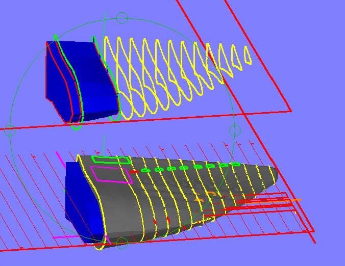
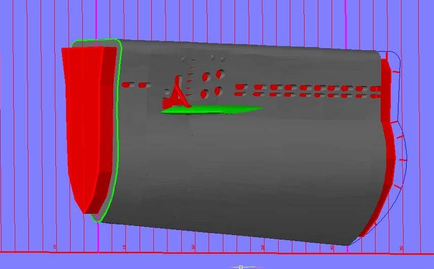
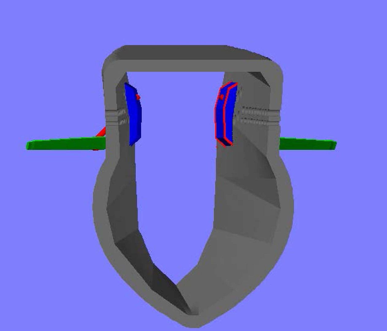
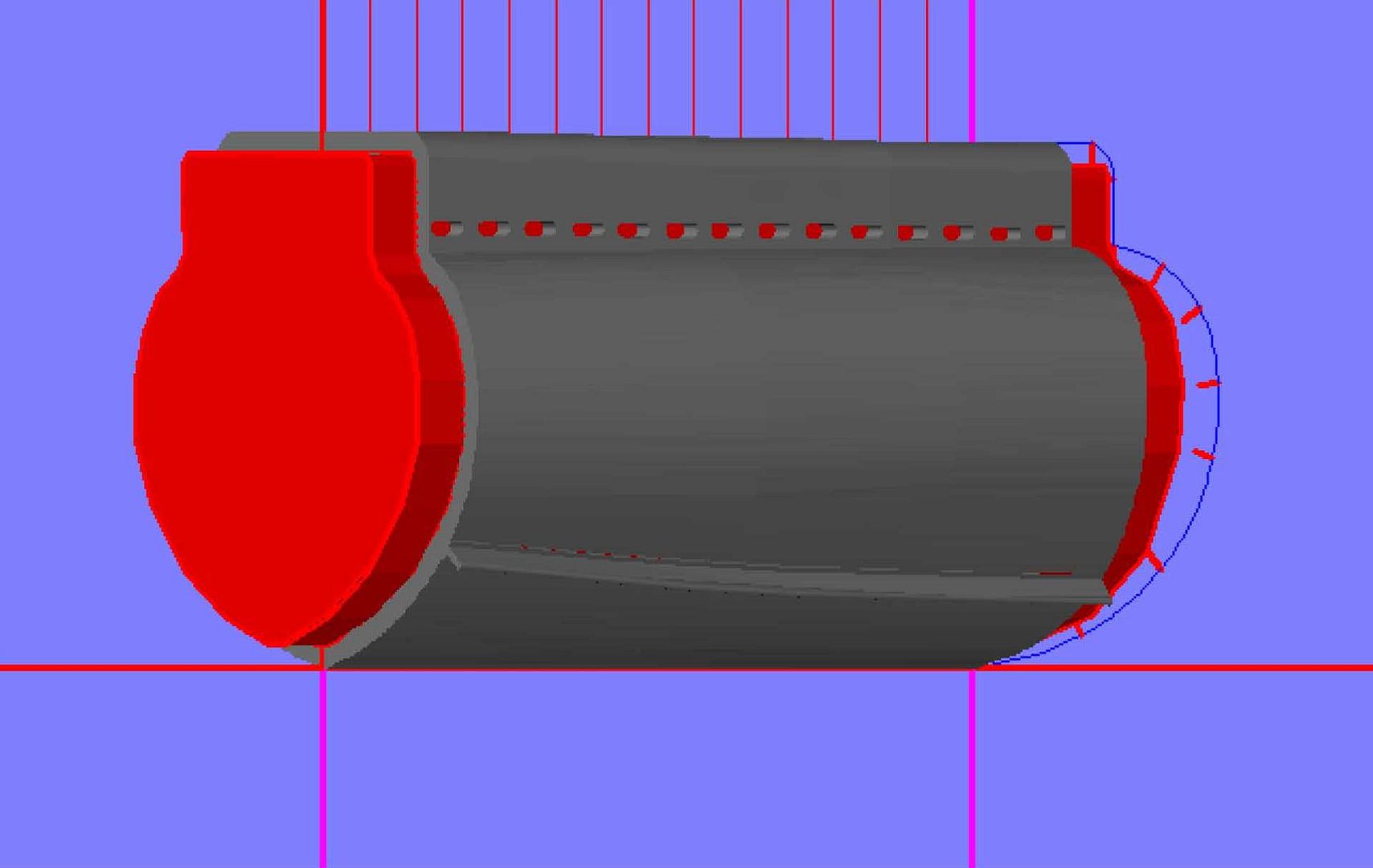
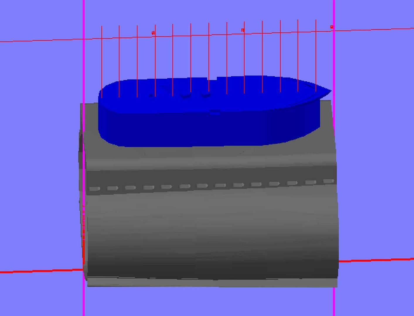
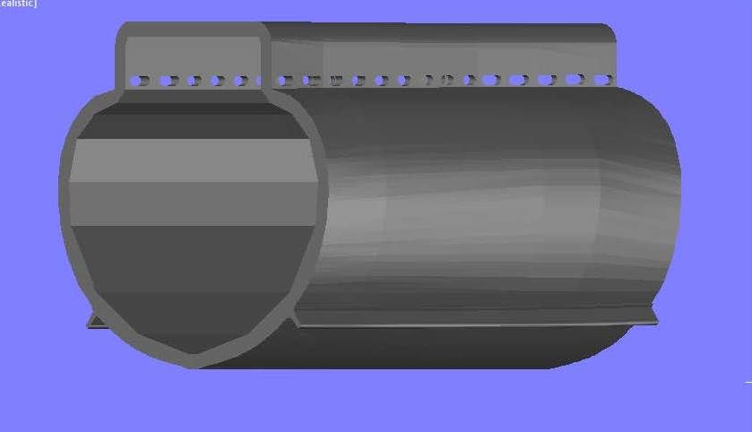
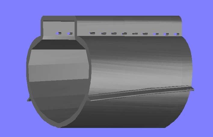
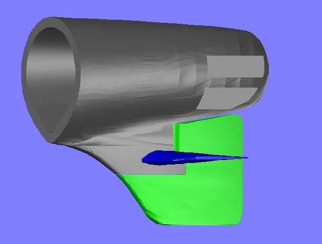
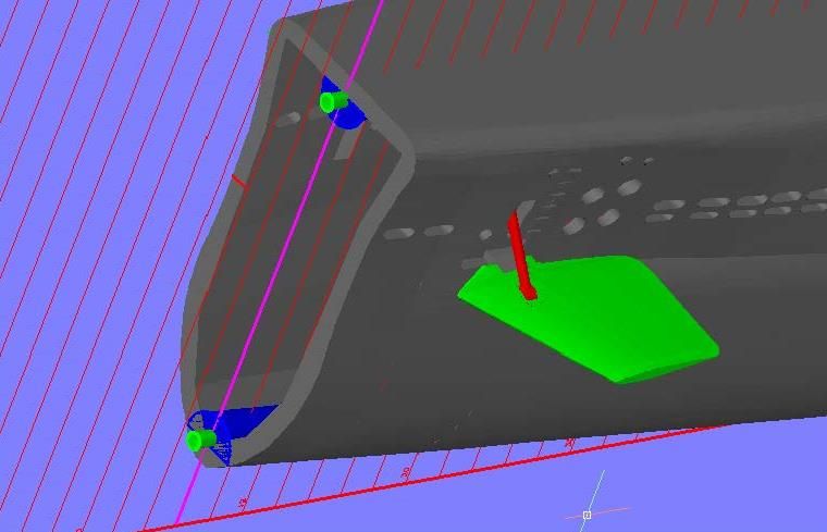
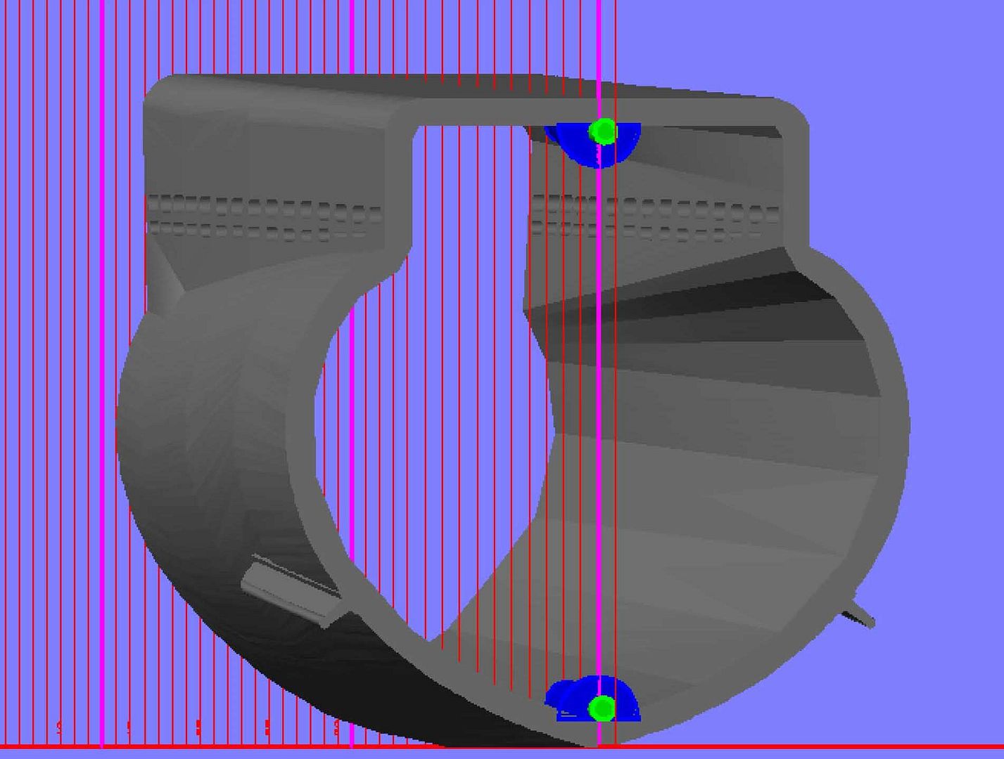
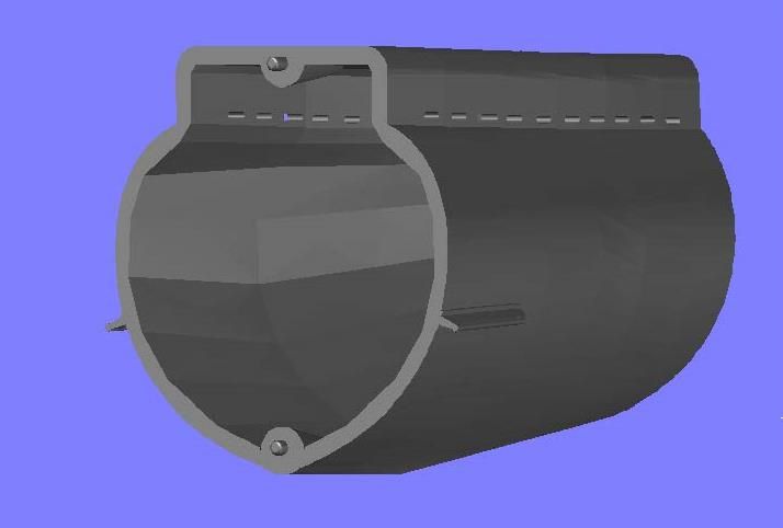
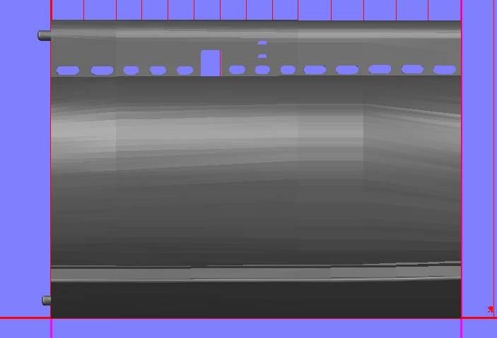
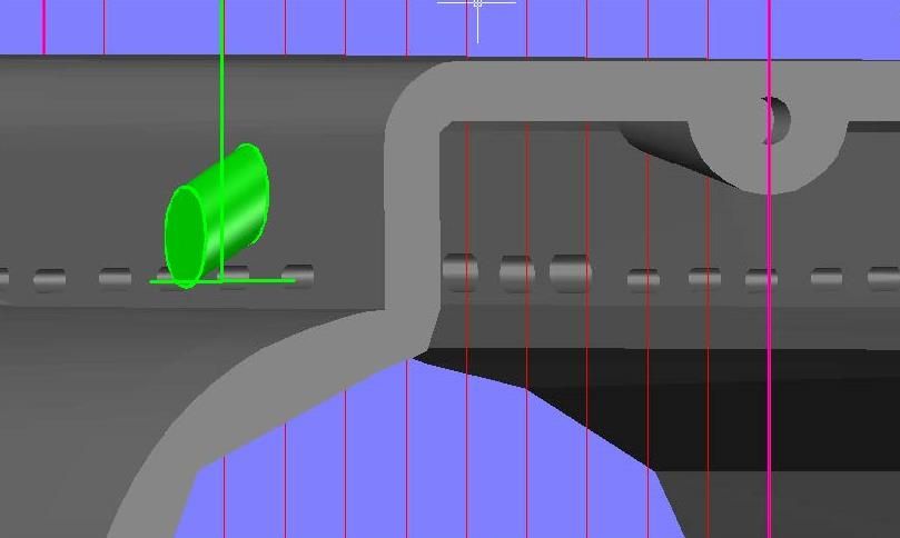
I then lofted all of the sections together, and it turned out to be a good thing that I had to redo it, because, with a smaller file, I was able to loft them all as one unit resulting in a much smoother loft than the original. Where was I? Oh yeah, back to the torpedo tube holes. So, I copied the oval shape I had previously drawn to its location as determined from pictures, and drew a circle also to match the photos.
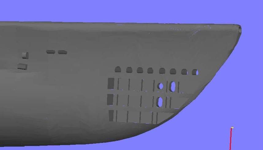
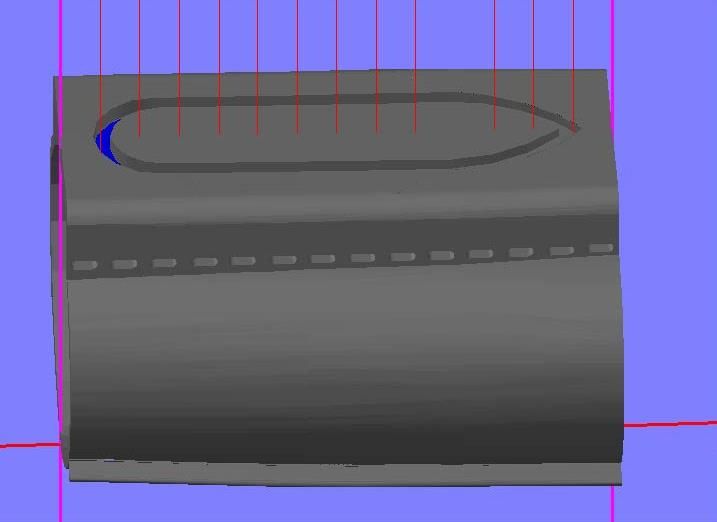
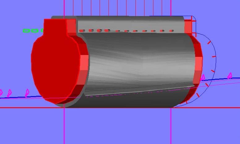
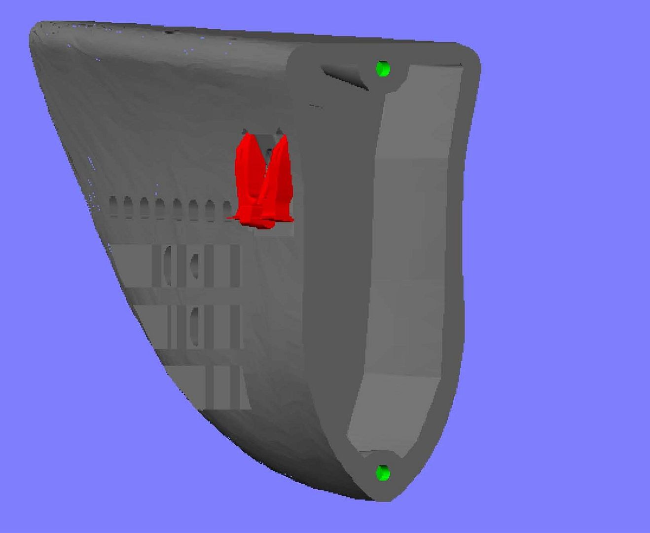
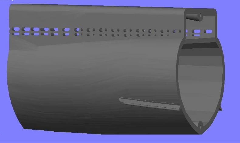
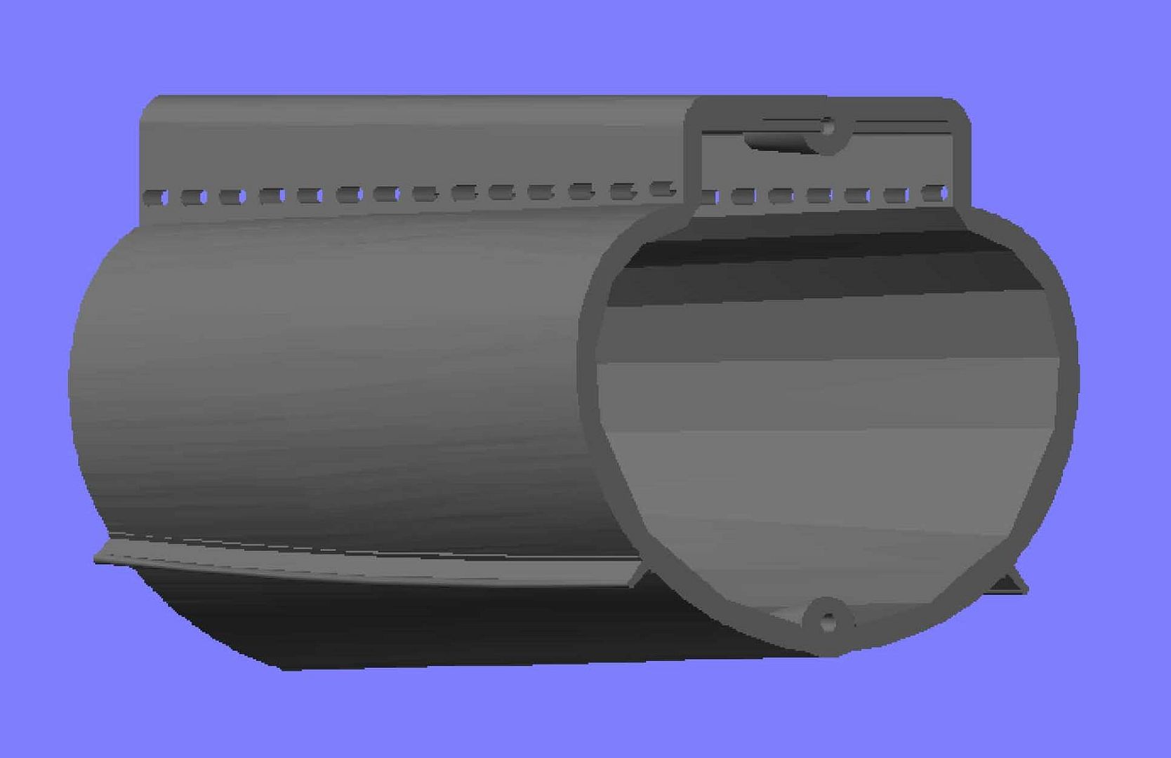
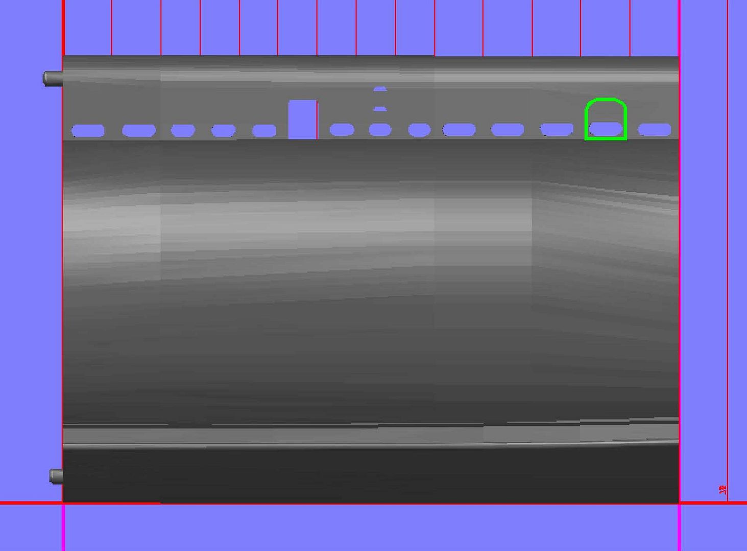
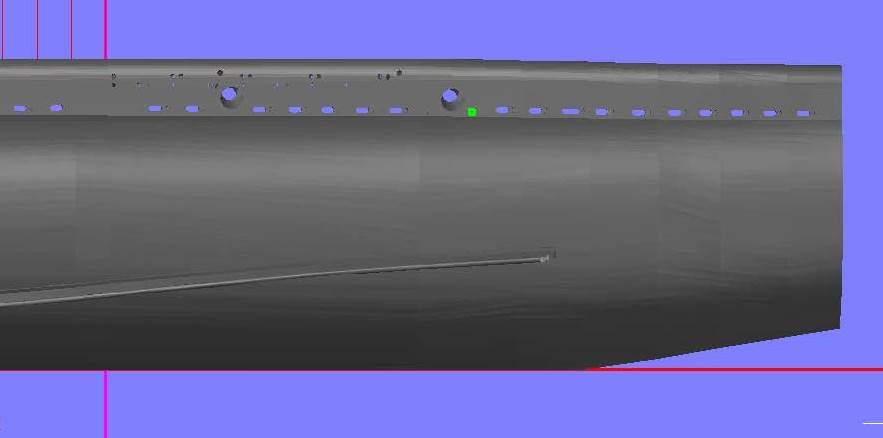
I then lofted these holes as well as the limber holes, and subtracted them from the new hull section.
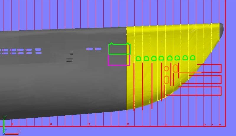
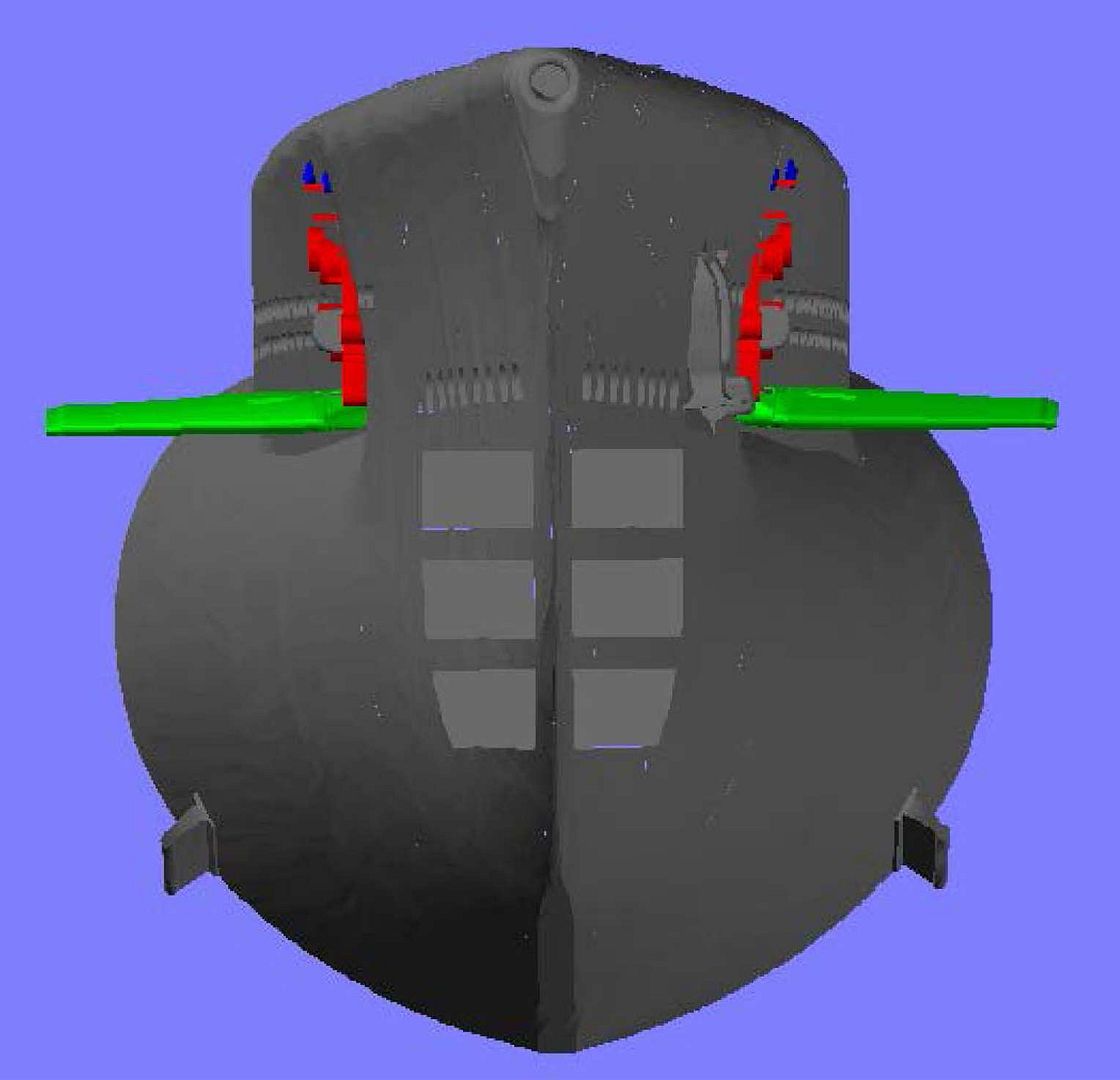
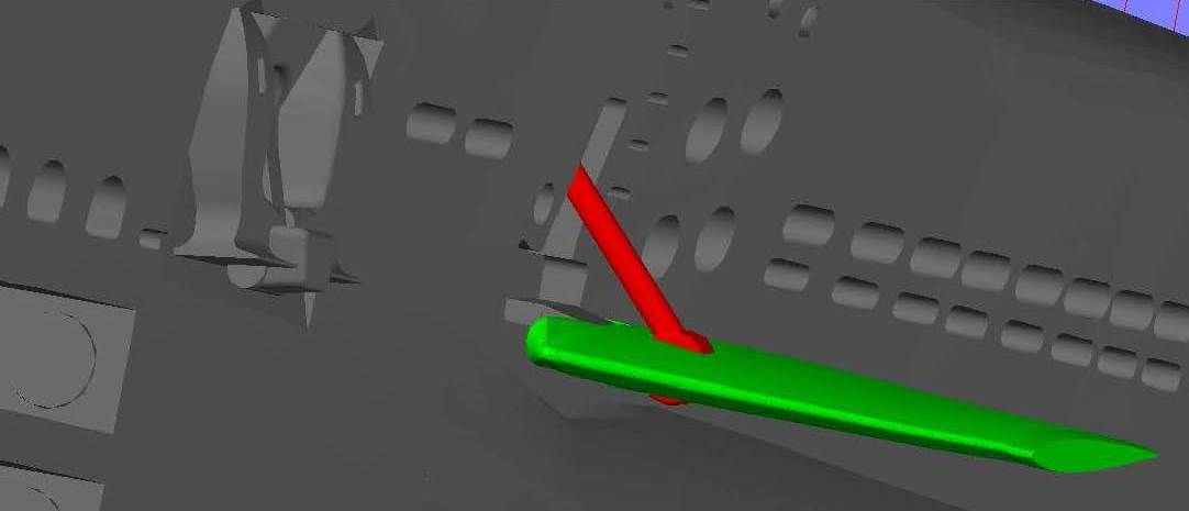
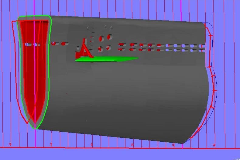
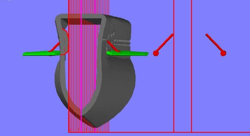
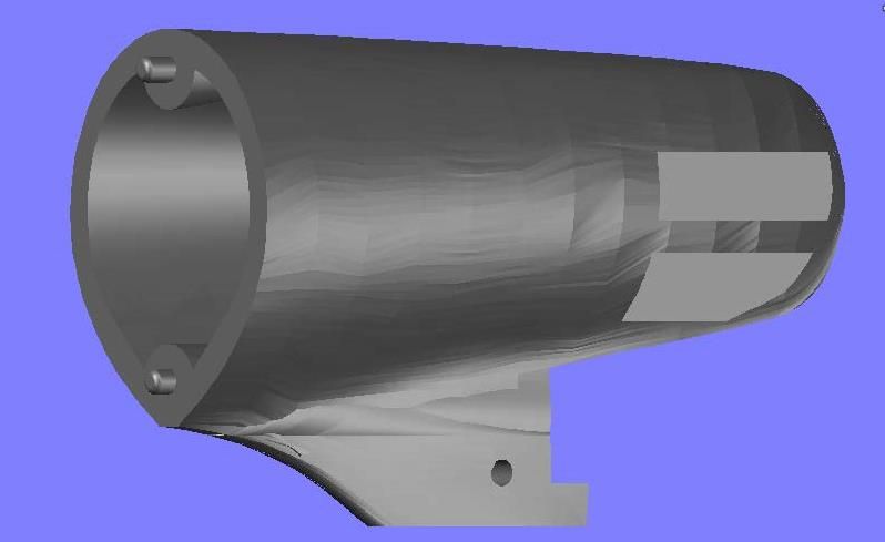
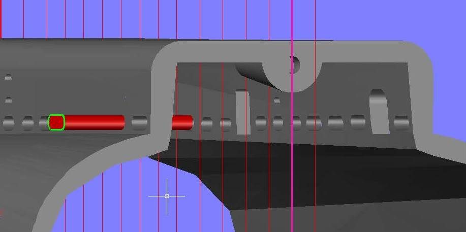
The next step was to extrude the torpedo construction lines and mirror them to the other side…
…And subtract them. I also had to cut the small sliver of the anchor well that was on the new piece.
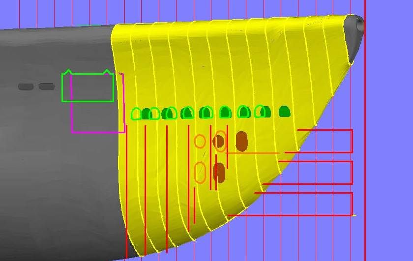
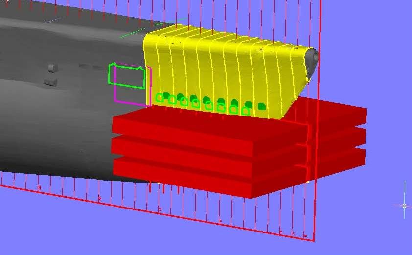
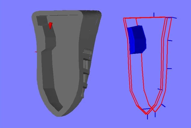
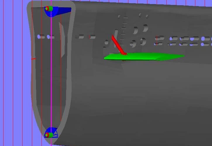
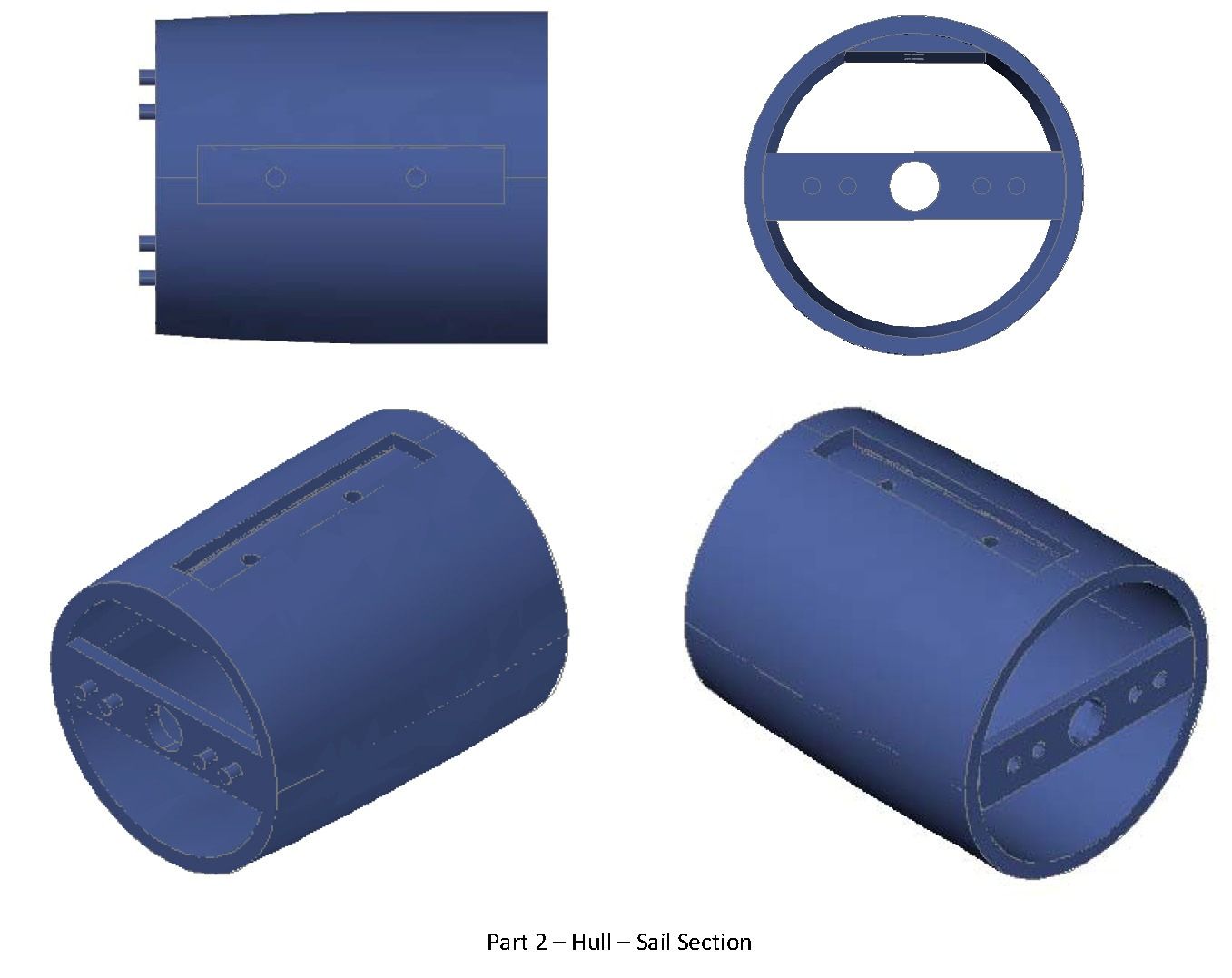
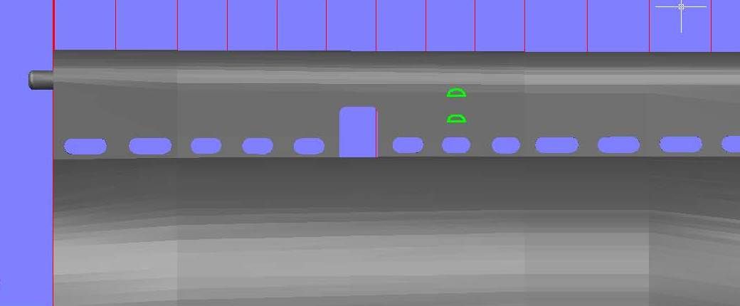
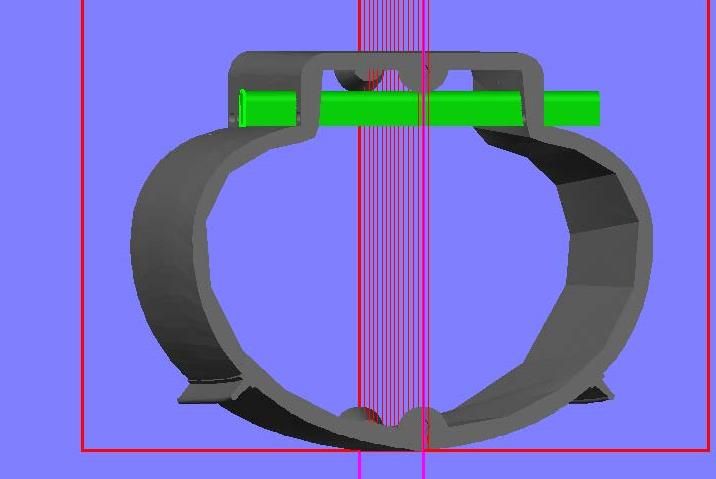
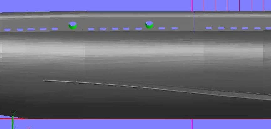
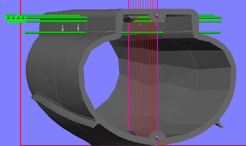
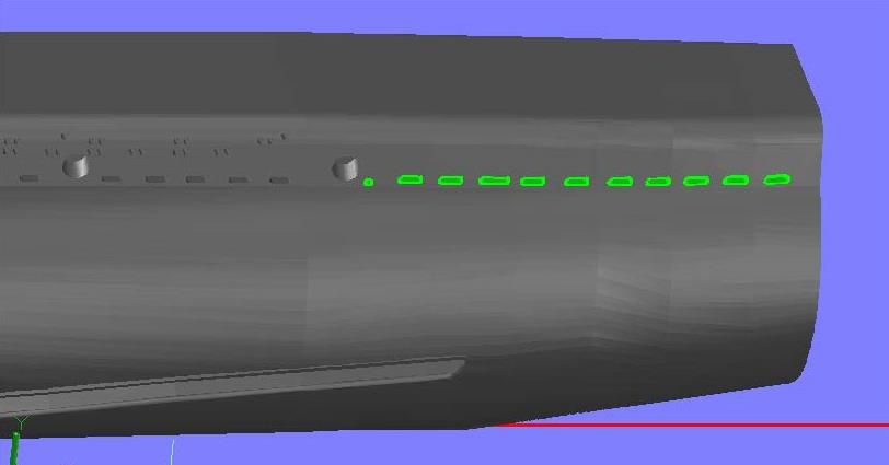
At this point I shifted my attention to the support bars. I started by drawing 0.5’ wide rectangles (0.04†at 1/144 scale), and lofting them so that they protruded from the surface 0.5’. Once again, the scale isn’t correct, but the effect is good.
Now what?
UPDATE 23
GREAT STUFF TOM D! I appreciate today's lesson.
Fixing my blunder with the starboard side anchor was, easy, as I thought it would be. It was simply a matter of slicing, copying, pasting, and rejoining.
After I completed that, I decided to do the detailing on the forward torpedo tubes. Using pictures for the design, I started with one of the oval holes.
At this point I started drawing the guide lines for the vertical support structures visible inside the “tubesâ€. It wasn’t looking right to me, and previously I had suspected that the forward limber holes may be a bit low, so I went to the plan sheet drawing and copied both the limber holes and the torpedo tube construction lines to the hull1 drawing. As you can see in the image below, my suspicions were correct. They are too low.
Fixing this required redoing the front end, so I sliced the hull from Frame 10 to Frame B, copied the sections to the appropriate frames and rotated them.
I then lofted all of the sections together, and it turned out to be a good thing that I had to redo it, because, with a smaller file, I was able to loft them all as one unit resulting in a much smoother loft than the original. Where was I? Oh yeah, back to the torpedo tube holes. So, I copied the oval shape I had previously drawn to its location as determined from pictures, and drew a circle also to match the photos.
I then lofted these holes as well as the limber holes, and subtracted them from the new hull section.
The next step was to extrude the torpedo construction lines and mirror them to the other side…
…And subtract them. I also had to cut the small sliver of the anchor well that was on the new piece.
At this point I shifted my attention to the support bars. I started by drawing 0.5’ wide rectangles (0.04†at 1/144 scale), and lofting them so that they protruded from the surface 0.5’. Once again, the scale isn’t correct, but the effect is good.
Now what?


 .
.


Comment