
Re: 1/144 Scale USS Batfish (SS310)
UPDATE 79
Hi Guys!
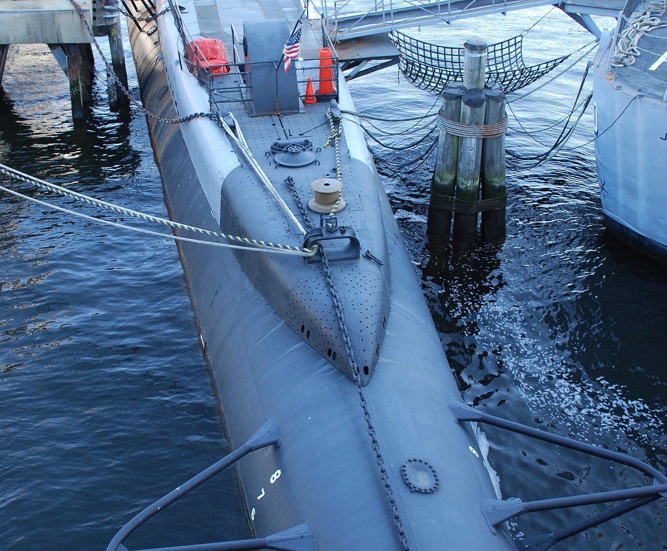
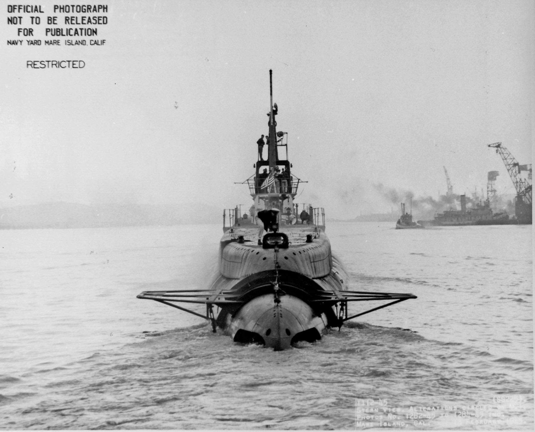
Before I started to add the cleats to the model I decided to look at pictures to see if I could find a good one of the aft chock, which is not currently on Batfish due to the access ramp, but surely was on her when she was in service. I didn’t have to look long as I soon found a picture that Tom D had previously sent that shows the chock nicely. The picture below is a clip of Tom’s pic.
To start the process of making the chock, I started with the chock I made for USCGC Bertholf, copying it into a file that I had previously copied the outline of the chock from the plans to.
Note that since Bertholf is in 1/350 scale, the chock is too small. When I scaled it up 243% the length was right on, but the width was too narrow.
So I made a Block out of it and stretched it in the y-direction.
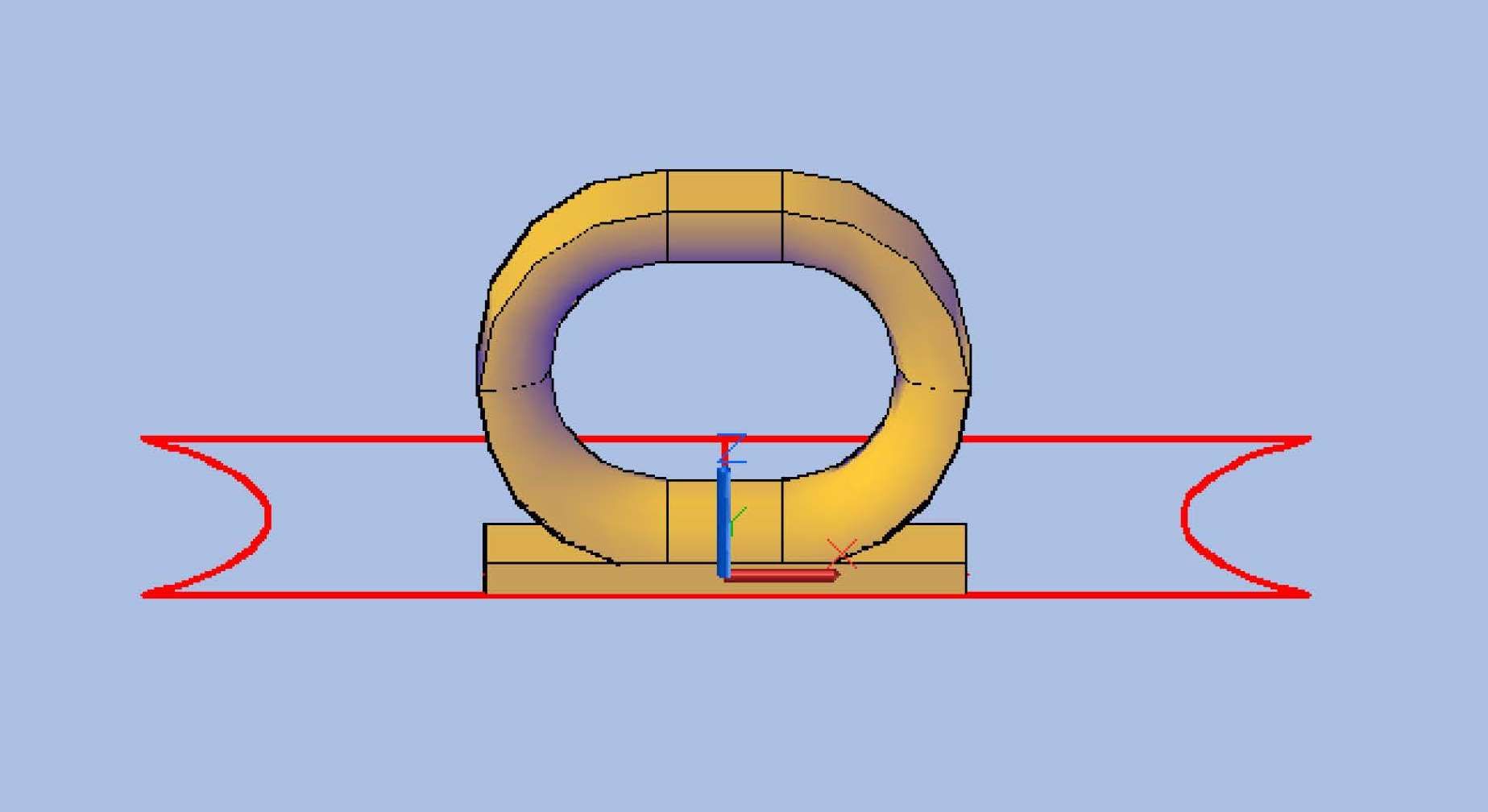
Unfortunately, AutoCad again wouldn’t let me explode it, so I essentially had to redraw it. The image below shows the guidelines I used to make it…
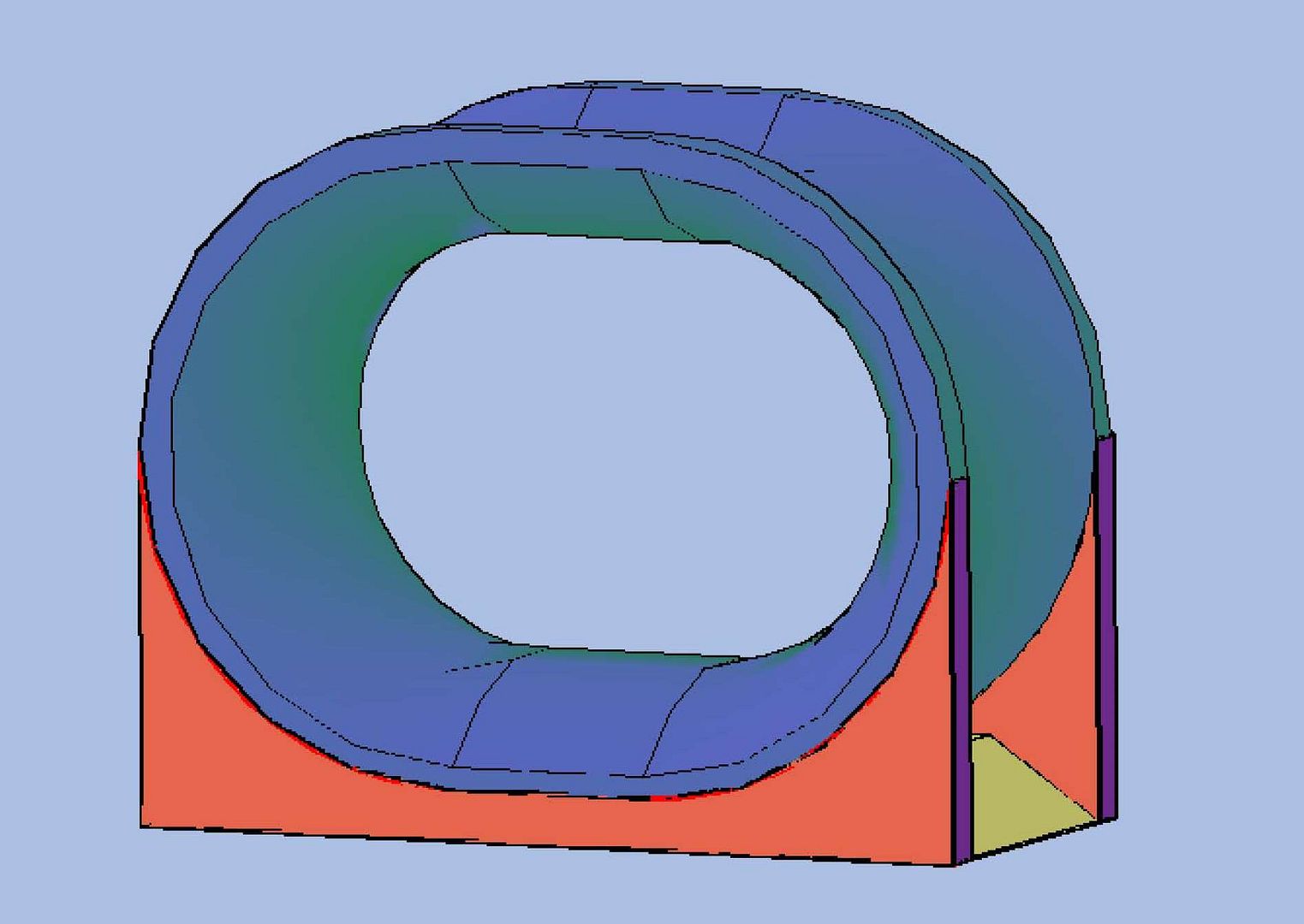
…First extruding the circles along the outer oval, then copying the outer oval out from the chock and extruding it through the chock…

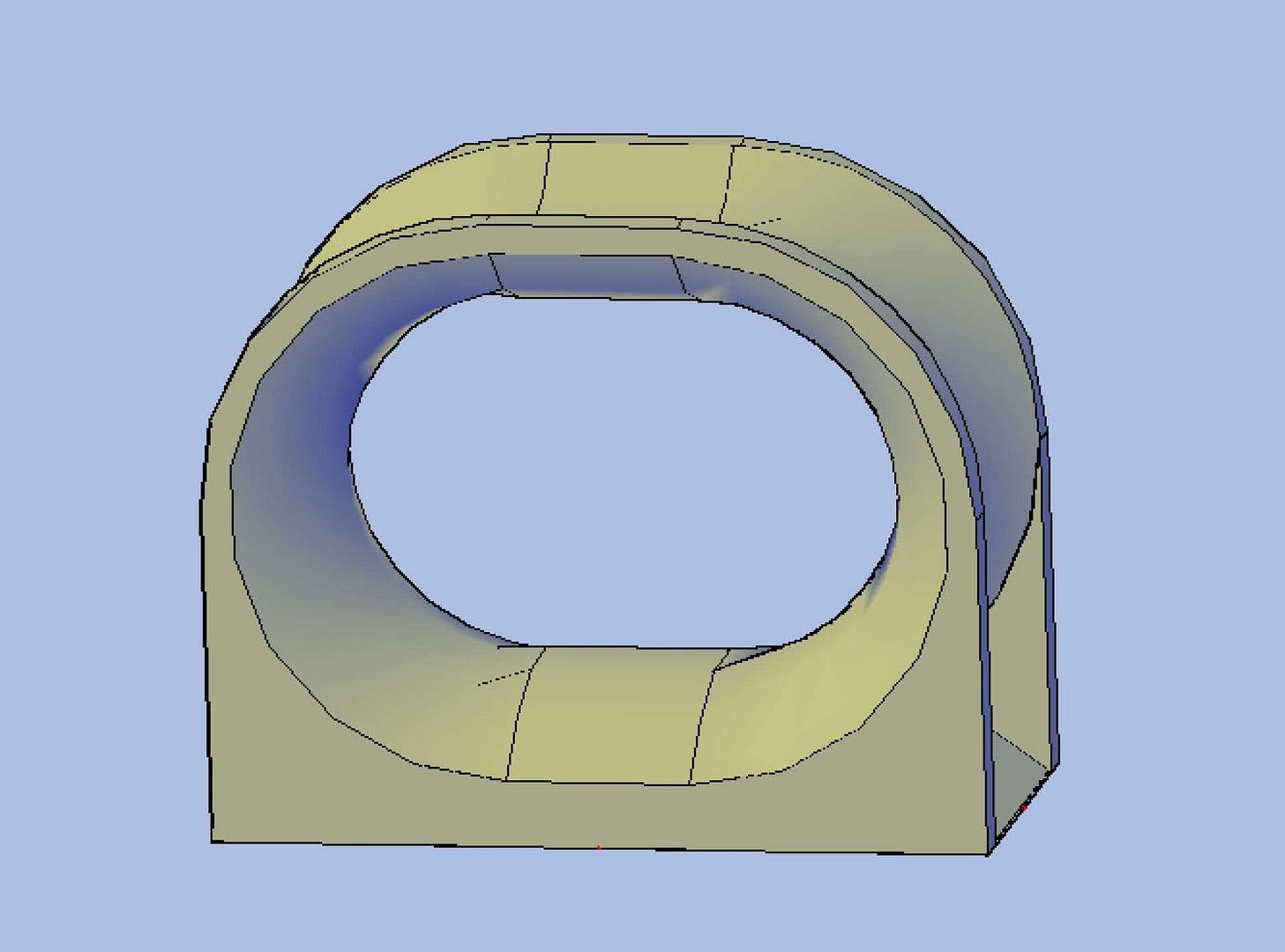
…Then using the Union command to define the chock.
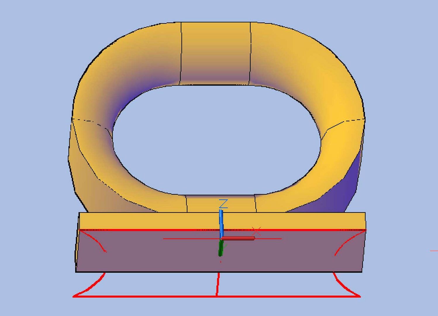
Next I subtracted the solid created by extrusion of the smaller circle from the chock.
With the main body of the chock complete I next prepared to make the base, which I did in 2 parts.

The red polyline was extruded just to cover the flange, and then was copied to the other flange.
The yellow polyline was moved into the interior of the chock…
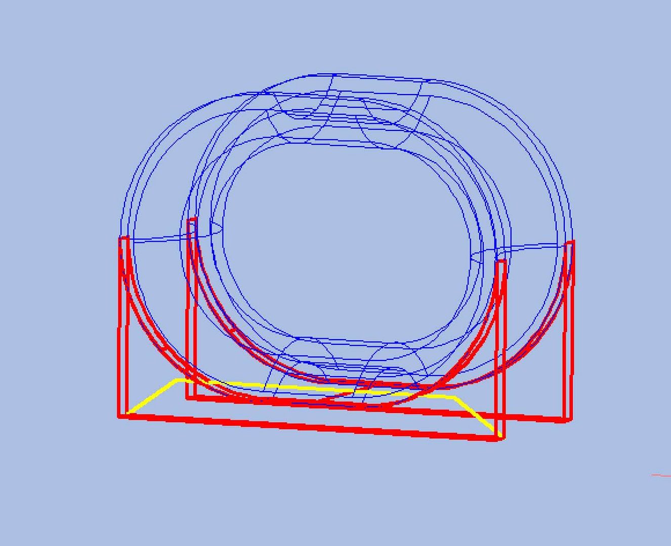
…Then extruded completely through to the other side.
This isn’t exactly how it is in real life, but I made it like this to provide more support and still replicate the real deal.
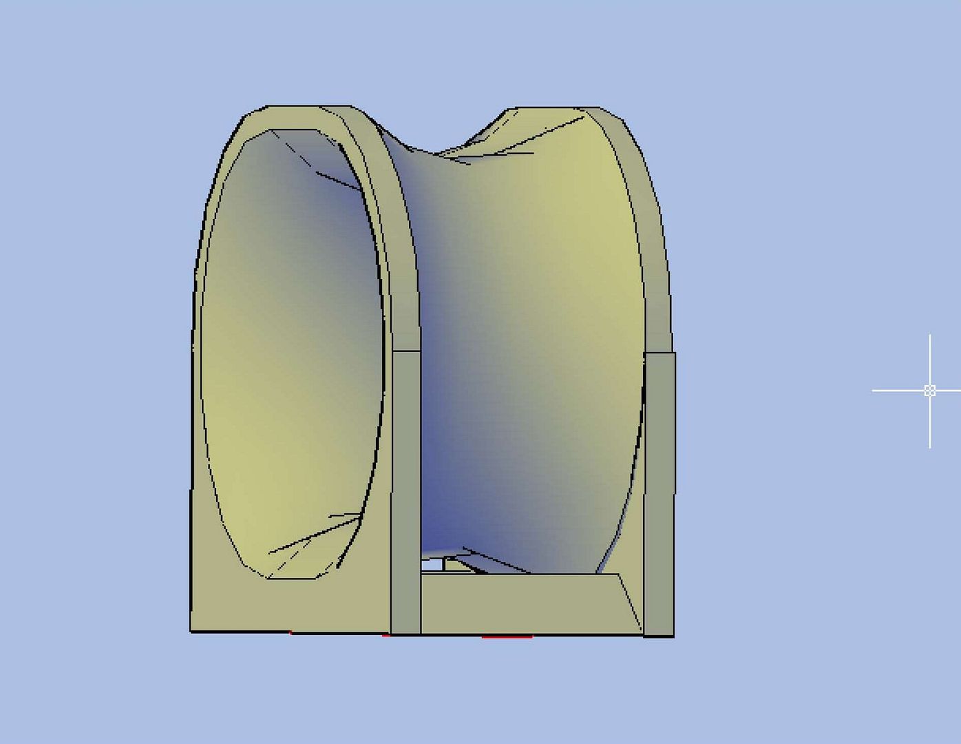
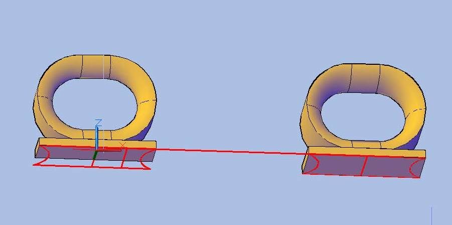
Next I started the base for the light on the top of the chock. I first drew a rectangle on top and extruded it through the chock, and then copied the whole thing to the side.
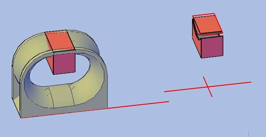
On the copied one, I subtracted the chock from the extruded rectangle.
Separated the parts and deleted the bottom part as well as the entire extrusion on the original.
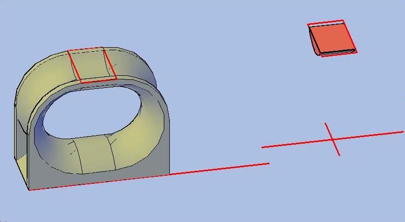
I then moved t he remaining part back to the original chock…
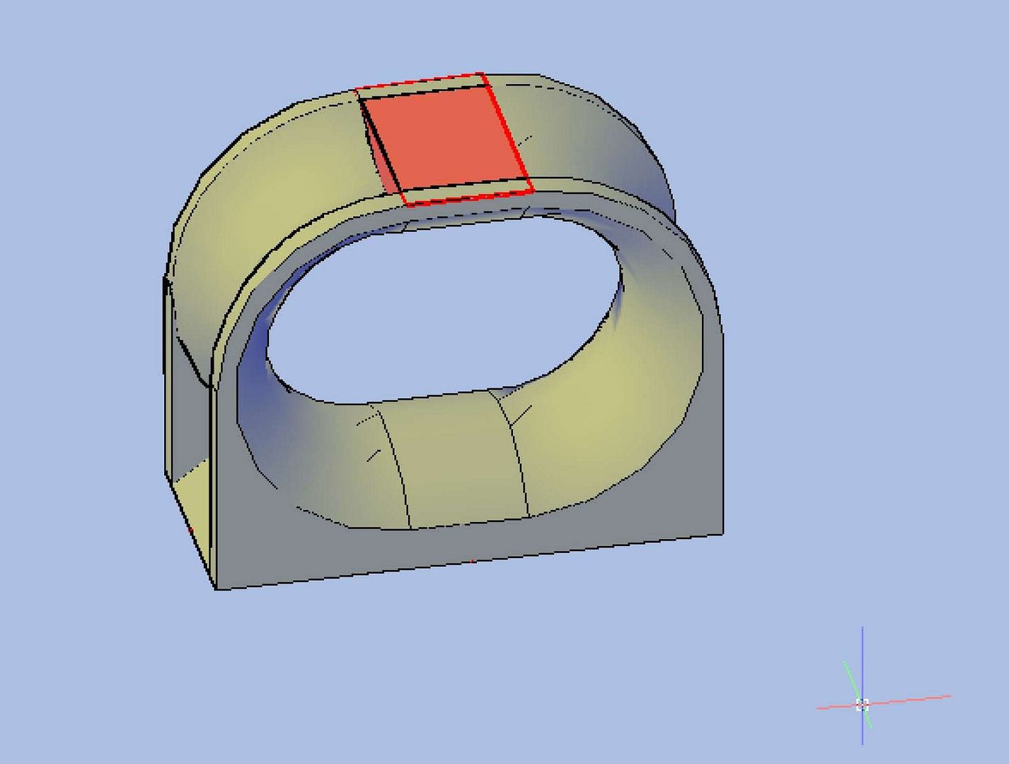
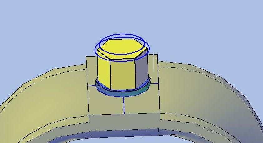
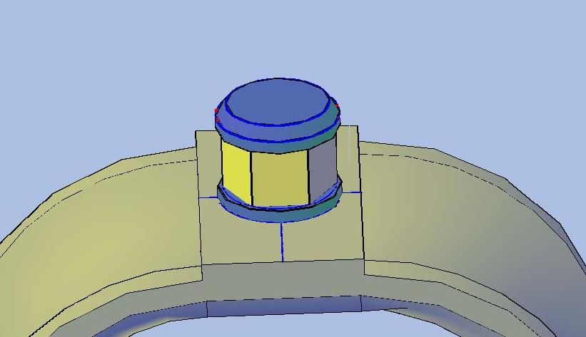
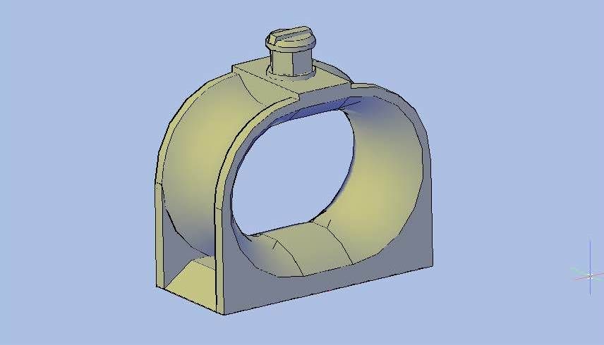
Next I extruded the rectangle up 0.005†and joined everything together, before preparing to make the light itself, which I did by extruding or lofting circles and a hexagon, as shown in the images below.
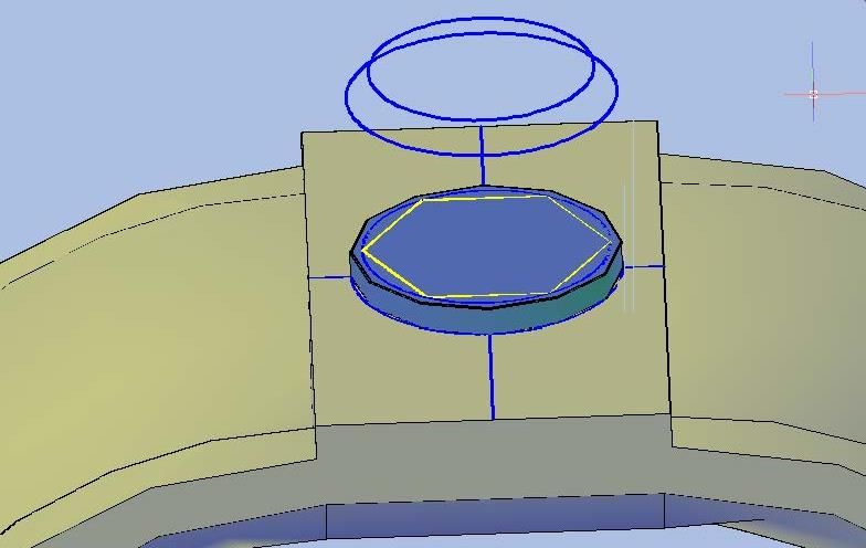
I also added the bar or cap on the top as seen in the picture, by lofting two different sixed rectangles.
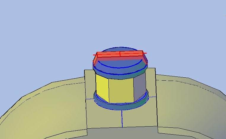
I then joined everything together, including the chock.
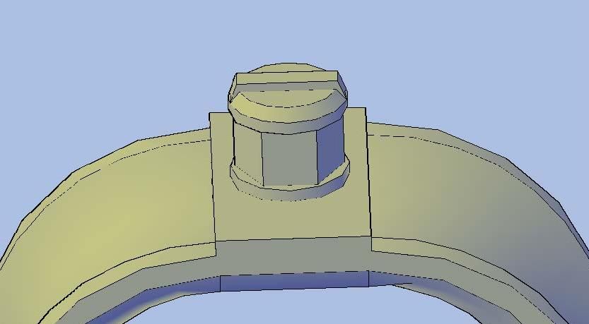
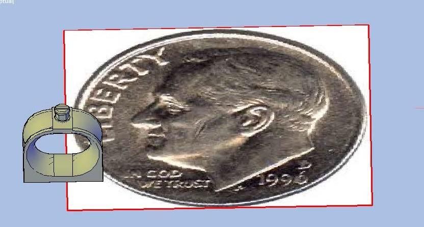
The image below shows it on the scaled dime.
CHEERS!!!
UPDATE 79
Hi Guys!
Before I started to add the cleats to the model I decided to look at pictures to see if I could find a good one of the aft chock, which is not currently on Batfish due to the access ramp, but surely was on her when she was in service. I didn’t have to look long as I soon found a picture that Tom D had previously sent that shows the chock nicely. The picture below is a clip of Tom’s pic.

To start the process of making the chock, I started with the chock I made for USCGC Bertholf, copying it into a file that I had previously copied the outline of the chock from the plans to.

Note that since Bertholf is in 1/350 scale, the chock is too small. When I scaled it up 243% the length was right on, but the width was too narrow.

So I made a Block out of it and stretched it in the y-direction.

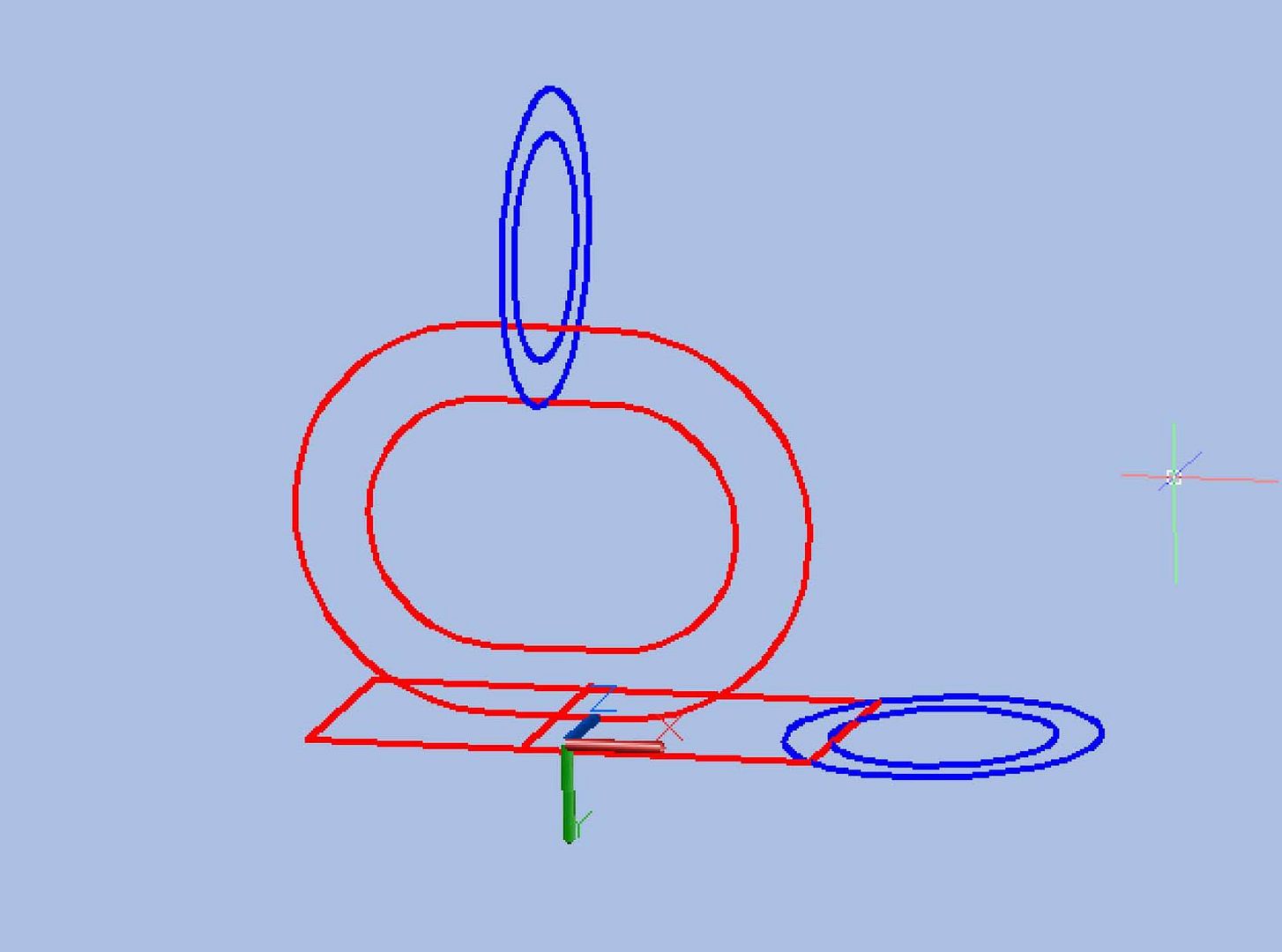
Unfortunately, AutoCad again wouldn’t let me explode it, so I essentially had to redraw it. The image below shows the guidelines I used to make it…

…First extruding the circles along the outer oval, then copying the outer oval out from the chock and extruding it through the chock…

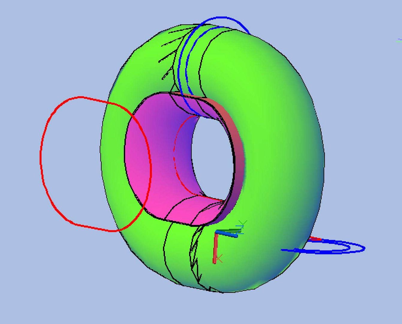
…Then using the Union command to define the chock.

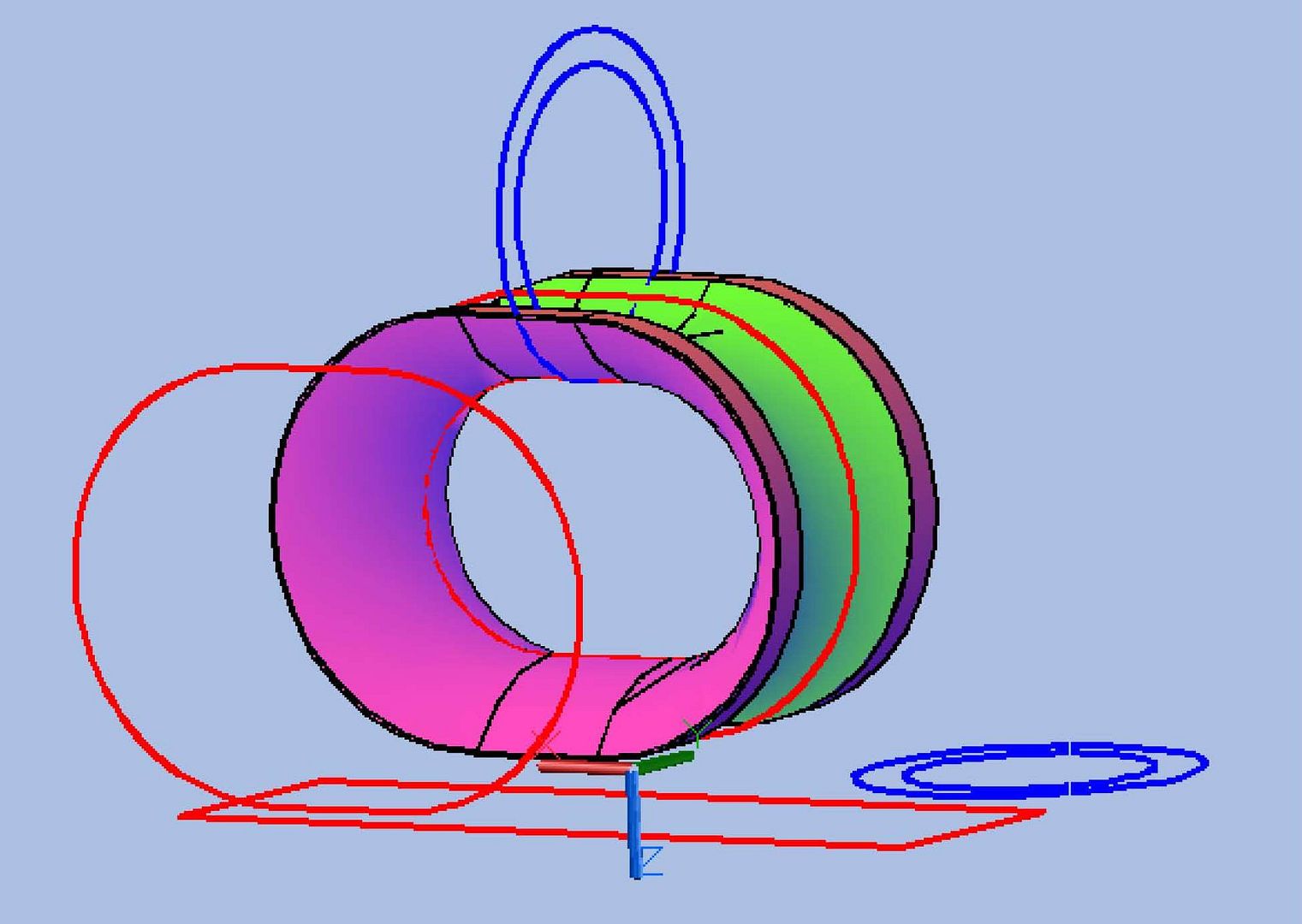
Next I subtracted the solid created by extrusion of the smaller circle from the chock.

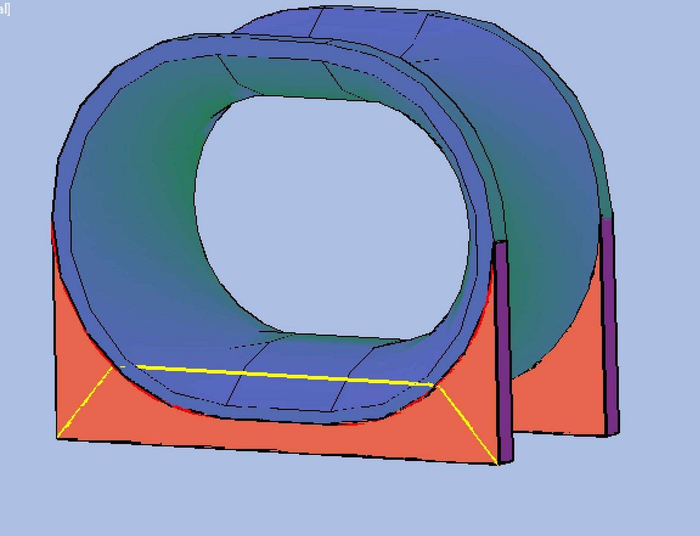
With the main body of the chock complete I next prepared to make the base, which I did in 2 parts.

The red polyline was extruded just to cover the flange, and then was copied to the other flange.

The yellow polyline was moved into the interior of the chock…

…Then extruded completely through to the other side.

This isn’t exactly how it is in real life, but I made it like this to provide more support and still replicate the real deal.


Next I started the base for the light on the top of the chock. I first drew a rectangle on top and extruded it through the chock, and then copied the whole thing to the side.

On the copied one, I subtracted the chock from the extruded rectangle.
Separated the parts and deleted the bottom part as well as the entire extrusion on the original.

I then moved t he remaining part back to the original chock…

Next I extruded the rectangle up 0.005†and joined everything together, before preparing to make the light itself, which I did by extruding or lofting circles and a hexagon, as shown in the images below.


I also added the bar or cap on the top as seen in the picture, by lofting two different sixed rectangles.

I then joined everything together, including the chock.


The image below shows it on the scaled dime.

CHEERS!!!


Comment