Need lots of help

Collapse
X
 
  • Time
  • Show
Clear All
new posts
  • Guest

    #76
    Fuses should be of the slow blow type, and of adequate rating. 10A will cover most small to medium size models. It's there to protect the wiring and the sub, rather than the electronics.

    Car type are good, but any style e.g. blade or cartridge will suffice. I know a lot of modellers don't run fuses, the only type of model I don't run fuses in, are flying machines. Should be fairly obvious why a fuse isn't a great idea in those.

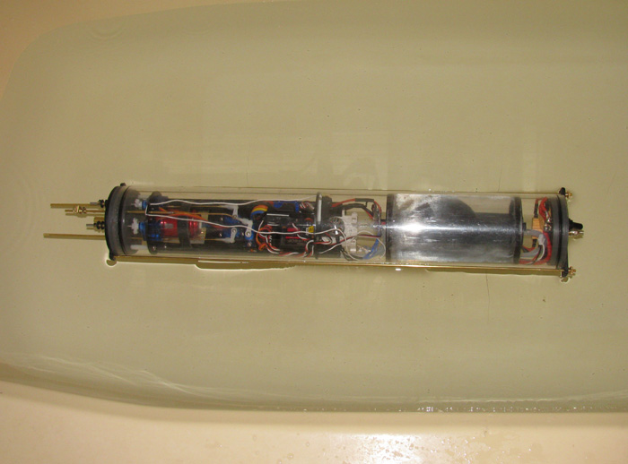
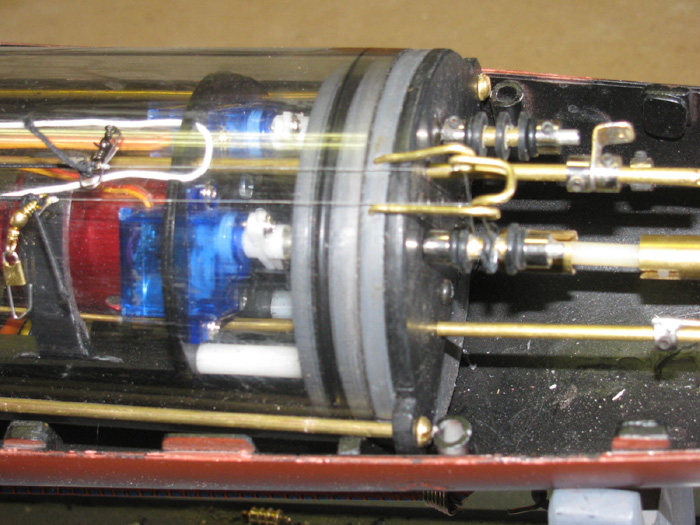
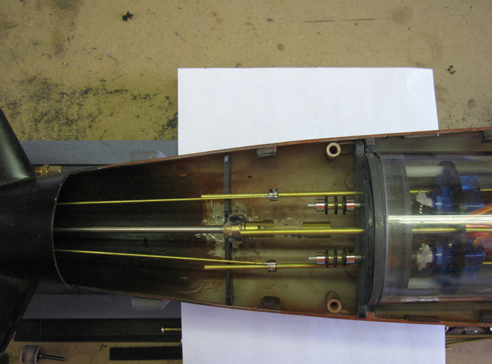
    Metal rods won't pose any problem for the radio, however you don't need those rods if you'd read my earlier post, you can use the hull itself to retain the endcaps, lighter, easier and more elegant, and no rods cluttering up the interior of your module.

    Comment

    • QuarterMaster
      No one
      • Jul 2003
      • 607

      #77
      SLA's can be mounted in ANY direction. Because I run them in the wet compartment, I run a single layer of Electrical tape around the cover seam shown here:

      Click image for larger version

Name:	2016-04-06 11.19.17.jpg
Views:	1
Size:	55.3 KB
ID:	128908

      Mr. Merriman advised that YEARS ago, that way the hydrogen atoms can still escape when charging/discharging, but the large H2O molecules stay outside. Is that proven scientifically? I dunno, I just quote the beast, and fwiw, I have no indication of shorter battery life.

      Since I turn model on by simply plugging the molex connectors together, they are in the wet side, I do get corrosion over time on the positive terminal. Molex connectors are cheap enough, and I have the original on my WTC that is 23 yo.

      FWIW, I am changing to those two prong rubber automotive trailer connectors. Just wrap it with a pices of elf amalgamating silicon tape IE: Rescue Tape every time you reattach it. 1 roll last's a season. Again, not so much because of the corrosion worry, more for the fact they'er easier to install, less expensive since you buy it, cut in half and and you know have both sides of the connection.

      One thing to note, the lead plates within the SLA are not truly symmetrical from TOP to BOTTOM, so for trim considerations, if you lay them on their side you need to align them properly:

      If you can lay them athwartships, do so. In this case I'm pointing toward the bow (or stern)

      Click image for larger version

Name:	2016-04-06 11.19.39.jpg
Views:	1
Size:	57.8 KB
ID:	128909

      If your'e forced to align the long axis of the battery like this (still pointing toward the bow or stern), you'll probably find the boat listing and will need foam or ballast to compensate.

      Click image for larger version

Name:	2016-04-06 11.19.52.jpg
Views:	1
Size:	58.2 KB
ID:	128910

      This is how I lay the batteries in my 80" SEAVIEW, alternating them along the long access of the ship cancels out the affect.

      Click image for larger version

Name:	2016-04-06 11.20.05.jpg
Views:	1
Size:	54.5 KB
ID:	128911

      Capici??

      ......fuhgettaboutit!!
      v/r "Sub" Ed

      Silent Service "Cold War" Veteran (The good years!)
      NEVER underestimate the power of a Sailor who served aboard a submarine.
      USS ULYSSES S GRANT-USS SHARK-USS NAUTILUS-USS KEY WEST-USS KRAKEN-USS PATRICK HENRY-HMS VENGEANCE-U25-SSRN SEAVIEW-PROTEUS-NAUTILUS

      Comment

      • Nb1914
        Junior Member
        • Mar 2016
        • 53

        #78
        Thanks and Yes "sub Culture" i would have preferred that, but i wanted something that would allow pressure testing bath testing etc out of the hull, I'm not sure i will use the rods yet. Also due to spec and gadgets exiting the rear bulkhead it would mean that to site the stops in the lower hull they would have to be quite low so applying un-even force on the bulkhead, probably doesn't matter with the pressures we are dealing with but just incase.

        Thanks Quarter master i had no idea about the weight distribution of the SLAs i only have room for one battery which would have to be running down the WTC length axis so if i go for SLA i will remember this.

        Comment

        • Guest

          #79
          Originally posted by Nb1914 View Post
          i wanted something that would allow pressure testing bath testing etc out of the hull.
          Why?
          Why?
          Why?
          Why?
          Why?
          Why?
          Why?
          Why?
          Why?
          Why?

          Comment

          • Nb1914
            Junior Member
            • Mar 2016
            • 53

            #80
            maybe its not necessary, but just so i can easily check the WTC for leaks without the hull getting in the way i.e. i can use the same wtc clamp mechanism outside the boat for testing as inside. Might be overkill but if i throw the WTC in the bath with the Clamping mechanism torqued at just thunb tight and all is well then the whole system is transfered to the hull.

            Comment

            • Guest

              #81
              The saddles that will keep the endcaps tight only need to be attached to the lower half of the hull, so you can still see what is going on in that regard.

              A simpler way to see if you have leaks is to use the old gas fitters trick of applying soapy water to all the joints pressurize, then see if bubbles form. That is much more reliable I find and negates the need to put it in a test tank.

              Comment

              • Nb1914
                Junior Member
                • Mar 2016
                • 53

                #82
                yes I'm thinking i might make the saddle clamps a part of the hull but with adjustment possible, i have 2 thick semi-circle perspex seats for the WTC to sit in the lower hull. I have drilled a hole threw both sides on each below the centre line, my intention was to pass the end to end clamping mechanism threw. But I'm now thinking i will connect up the WTC to x rudders etc get everything neutral then i can at the rear use 2 short lengths of nylon studding to provide a stop for the WTC by simply bolting the length of stud to the WTC seating saddle and the other side to the clamp still at the same end i will bolt both sides of the WTC to lock it and also the end brace with the WYC pushed firm against this is now the position the WTC needs to be in. NOw at the other end i can do the same but at this end the there is no double bolting so the as i tighten the clamp it pushes the WTC back against the hard stop at the other end. This way i v=can make balancing adjustments. Hard to explain so i will send a picture tomorrow.

                Comment

                • Nb1914
                  Junior Member
                  • Mar 2016
                  • 53

                  #83
                  I will put this to the vote the 2 methods i am considering using , also notice the additional flange O ring or gasket i have placed on the end bulkheads, these are not present but it might provide double protection ????:-

                  Click image for larger version

Name:	Drawing17.jpg
Views:	1
Size:	91.8 KB
ID:	128912

                  as i see it for pros and cons for each

                  method 1 = PROs = provides positive repeatable WTC location within the hull / is easy to assemble / fine adjustment of WTC position
                  CONs = if i want to leak test the WTC in the test tank the lower hull will have to be incorporated in the test (not sure this would be an issue)

                  Method 2 = PROs = WTC and clamping is separate to the hull / allows complete WTC leak testing as a unit without incorporating the lower hull
                  CONs = More difficult to assemble as end-end rods have to be pushed through the WTC saddle clamps, WTC positioning slightly more difficult.

                  How do you guys see it ?????

                  Comment

                  • Ralph --- SSBN 598
                    Junior Member
                    • Oct 2012
                    • 1417

                    #84
                    This may be one of those times that over engineering is being considered.

                    Being able to move the wtc requires more work in designing the end cap bolts to mate up with the saddle holes.
                    Requires more work to remove and install wtc in to hull.

                    The second one requires more work as you stated.
                    ==========================
                    I may have shown this photo before.


                    The cap retaining rods go down the outside on each side of the wtc.
                    The frames or saddle rings have been cut to allow the rods to drop down.
                    These notches keep the wtc from twisting do to prop torque.
                    At the from of the cylinder in the hull are stops so the cylinder will always be in the same place.
                    At the rear of the cylinder there are stops to hold the cylinder from moving back.
                    There is about 1/16" clearance to allow for heat and cool expansion.

                    There is a single Velcro strap center of the cylinder that is bonded to the lower hull that keeps the cylinder in the hull.
                    Loosen the control rod wheel collars and separate the Velco strap from itself and the cylinder lifts out.

                    Trim is done with weights and foam in the hull.
                    Fine trim is done by moving the ballast tank and battery in the cylinder during final water trimming.

                    Front of cylinder shows the rods against the hull alignment sockets.
                    A plastic block was installed in the bottom of the hull.


                    Rear of cylinder before stop blocks where installed between cylinder rod tabs and hull alignment socket.
                    I actually had to remove the socket down 3/4" to allow my top hull to slide back for locking top to bottom hull.
                    The stops are down 3/4" from the top edge of the hull lip.


                    I do not seem to have any photos showing the complete cylinder in the hull.

                    A note: My built was a copy of Tim's built.
                    He first built his wtc with sections held together at multiple caps with lots of little screws.

                    He was months ahead of me and he did a lot of testing.
                    He made changes along the way.
                    He changed the pump motor.
                    I was able to do the same.

                    Then he changed the cylinder to a single tube.
                    His next report was of pressure build up during a dive and end cap popping out of the cylinder.
                    At this point I decided to go with the full length retaining rods.
                    He has since installed some sort of retain system.


                    I may not be explaining this correctly.
                    So, here a link to Tim's build.
                    It is full of good useful information and photos.
                    Tim's Sculpin build

                    Comment

                    • Nb1914
                      Junior Member
                      • Mar 2016
                      • 53

                      #85
                      Thanks Ralph, i couldn't mill out slots on the WTC saddles as there are hooks in the tops to provide a means to secure the WTC, i dont think with either option that the WTC could twist but conveniently on the rear bulkhead there is a spare threaded hole which i could use to bolt to the rear clamp. I will have a look through Tims build later tonight.

                      Comment

                      • Nb1914
                        Junior Member
                        • Mar 2016
                        • 53

                        #86
                        back to batteries, I'm having trouble finding a decent capacity battery either SLA or Lipo that will fit inside the WTC, its the lengths which is the issue SLA batts are shorter but with poor capacities i.e. 08Ah 1.3Ah etc biggest lipo i can find at present is 3000Mah. I have a brushless 400kv main drive motor and a brushed 360 for the ballast. I can fit 2 3000Mah batteries one on top of the other. As per the advice given earlier I don't want to connect batts in parallel, so I'm thinking of using the 11.1v 3000Mah lipo for the main drive receiver/servos etc and using a lower capacity purely for the ballast motor, do many people do this.

                        Comment

                        • Nb1914
                          Junior Member
                          • Mar 2016
                          • 53

                          #87
                          As a thought so far i have based my battery selection of 11.1-12V , perhaps i should look at 6v as do i really need to reach maximum power on the brushless motor ??. a 6V battery gives me better selection on size for capacity ?

                          Comment

                          • Nb1914
                            Junior Member
                            • Mar 2016
                            • 53

                            #88
                            My plan , i will run at 14.8v with a parallel battery setup with each positive leg protected with a 16A schottky rectifier and the combined output protected with a 10Amp time delay fuse. This way i get good capacity that will fit in the WTC and low current, capacity usage for the same power.

                            Comment

                            • Ralph --- SSBN 598
                              Junior Member
                              • Oct 2012
                              • 1417

                              #89
                              I am not a motor or radio guy.
                              My build was to follow Tim's build as close as I could.
                              He made changes.
                              I made changes to continue following.
                              This is for reference.

                              The motor choose was this one.
                              Turnigy TrackStar 21.5T
                              Battery I used is a 2600 2S 7.4v.

                              The motor is programmable.
                              As Tim suggested, I programmed the motor to 30% forward and 30% reverse.
                              First time at the pond, things did not go well at all.
                              With everything bench checked, in to the water the boat went.
                              Checked again then applied forward power.
                              This is when complete panic hit.
                              On my transmitter, I pushed the stick forward and the boat took off so much faster that expected.
                              Found neutral and got the boat stopped out in the pond.
                              Then I pushed the stick forward again.
                              I pushed the stick, one whole mark on the Tx.
                              Again the boat was too fast.
                              So, I got away from others and slowly work the boat to shore.

                              At home on the bench, I knew I had to slow the motor down.
                              I didn't really want to take the motor out to reprogram it.
                              Option was to learn more about my Tx.
                              It was new to me.
                              Found a bunch of menus and started looking.
                              Hey, I can change the % on the sticks.
                              I spent some time trying different settings.
                              The motor is still set at 30%.
                              At the Tx, I have reset the throttle to 35% forward and 25% reverse.
                              I now have control of the propeller.
                              I can make it turn slowly, up to fast.
                              I learned how to do this and wrote a check sheet so I can make changes at the pond.

                              I am working on two other boats.
                              I have come to two conclusions.
                              If the Tx adjustment and programming the motor lower works, I will use it.
                              If not, then I will build some sort of gear reduction unit.
                              Thinking at least 6 to 1.

                              About my 2600 2S LiPo battery.
                              I charged it to go to the pond last April.
                              I have been using it to test on the bench.
                              Last week I ran the Rx and some of the servos for 2 hours.
                              The point is, I have NOT recharged the battery from last year.
                              Tim had said he ran his boat at the Colorado gathering for three days without recharging.

                              I am thinking this 2600 2S will run the boat long enough for me.
                              I do have two of these batteries.
                              Good to have a back up.

                              Comment

                              • Nb1914
                                Junior Member
                                • Mar 2016
                                • 53

                                #90
                                Unfortunately finding a decent 40mhz radio here is hard so the one i have has no option to rate limit on the sticks, i want to make sure the sub doesn't plane through the water like a speedboat so I'm after duration from the power system over out and out power. Only issue i have now is that the ballast motor which is a basic brushed motor has no markings on it so i need to be careful with the voltage i use with it. So i will probably use a low voltage low capacity battery purely for the Ballast pump.

                                Comment

                                Working...
                                X