Need lots of help

Collapse
X
 
  • Filter
  • Time
  • Show
Clear All
new posts
  • Nb1914
    Junior Member
    • Mar 2016
    • 53

    Need lots of help

    Hello All,

    I am just venturing into RC subs and finding that the subject is not as simple it sinks it floats. I have purchased a partly made 1/96 JMSDF and i have so many questions so I'm hoping with this forums help i will end up with a good operating sub, here goes.

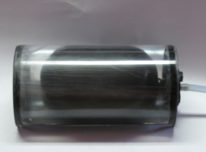
    The sub has been partly built very well, i have figured out that it has a high pressure ballast tank. There are only 2 servos operating the x rudders and i have an Engel DLx2 pitch controller and leveller. The servos have not been connected to the rudders and all i can deduce is that each servo via the DLx2 will operate diagonally opposed rudders in synchrony via a common pushrod assembly. Im not quite sure how this is mechanically setup i.e. i have seen some pictures that show a bar with servo horns that the servo pushrod attaches to then the rudders common pushrod attaches to the horn as well but what i can't see is how the other diagonally opposed rudders could also use the pivot bar ? the below picture (if no picture is present its my MAC skills gone to pot) shows what i mean, in pictures i have seen there is also an addition servo which has a pushrod also exiting the rear bulkhead ? the guy that originally started this sub looks like he knew what he was doing ad has only installed 2 servos, what could the third servo be for ?

    Additionally i want to employ failsafe equipment for depth exceeded, loss of radio etc i can see mention of pressure switches etc but what equipment should i purchase and from where. I think the ballast pump is a 2 way pump which i will run off the Airplane rudder channel i.e. left fill right empty, do the pumps usually have an internal pressure switch that at max it automatically stops . regarding safety devices dlx2 etc i am finding it hard to find a good wiring diagram.

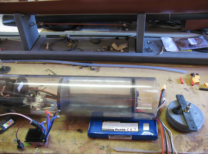
    the WTC has at the rear bulkhead a bicycle style schreader valve. i imagine this is to test the WTC under pressure for leaks, but there are 3 compartments the centre one containing the ballast bag and which is sealed from the front and rear compartment, i can see how pressuring the front and rear compartments might work as they are linked by a brass pipe running through the ballast compartment for wiring purposes. How can you tell if the ballast compartment is airtight other than maybe some clever maths on volumes and related pressures.

    when a sub with a static ballast system dives i.e. lets say you fill the ballast tank to 20% volume if this causes negative buoyancy and the sub sinks what stops that from continuing to sink and sink i.e. how do you hold a static depth, is it the pressure as it sinks causes more ballast required to sink further ?

    As you can see subs are a new venture. any help much appreciated.
    Last edited by Nb1914; 03-31-2016, 12:59 PM.
  • wingtip
    SubCommittee Member
    • Dec 2004
    • 323

    #2
    really need pics to help point you in right directions but sounds like an rcabs setup ????? as far as the x tail goes if you are using a modern computer radio you could do the mixing there but if your just using a standard non programmable radio there are x tail mixers you can buy to do the mixes your radio cant. as for pressure switches there are some on the market...rcsubworkshop sells a few but most people just program for loss of signal (again providing you have a programmable radio, if not there are failsafes you can purchase)... as for the bladders most build a switch into their system so that when the bladder expands to a certain point it will push the button on the switch, usually a push to break momentary, which stops the pump motor.....

    as for holding a steady depth that depends on boat trim, specifically the neutral buoyancy. but it can also be affected by depth as the density changes the deeper you go... also if you do run an rcabs setup keep in mind if you do to deep, as the pressure increases you may not leak yet but your bladder pump might not be able to pump up the bladder to overcome the pressure on the bladder.... this is why some people set their boats with just a slight positive buoyancy and not quite neutral...so that there is more chance of boat returning to the surface and not just sinking to Davey jones 's locker..lol but in a nutshell you trim the boat with the ballast tanks full


    have you seen Steve Neill's RC Sub Building for Dummies ???? its a nice start.... Also check bobs site out http://www.rc-sub.com/home/index.php5
    Last edited by wingtip; 03-31-2016, 02:46 PM.

    Comment

    • Nb1914
      Junior Member
      • Mar 2016
      • 53

      #3
      Click image for larger version

Name:	20141113_101010_resized.jpg
Views:	1
Size:	95.5 KB
ID:	128868

      hopefully the pictures are ok

      Im not sure its an RCABs setup as there is no reservoir to pump the air to, it looks like water is pumped in and out.

      Click image for larger version

Name:	20141113_100926_resized.jpg
Views:	1
Size:	91.4 KB
ID:	128869Click image for larger version

Name:	20141113_101124_resized.jpg
Views:	1
Size:	96.6 KB
ID:	128870Click image for larger version

Name:	20141113_101110_resized.jpg
Views:	1
Size:	99.9 KB
ID:	128871

      Comment

      • Nb1914
        Junior Member
        • Mar 2016
        • 53

        #4
        and some more, note the first servo no idea what this is for, also i have a basic 4 channel 40Mhz radio, x rudder mixing will be handled by the Engel DLx2 unit.

        Click image for larger version

Name:	20141113_101028_resized.jpg
Views:	1
Size:	95.2 KB
ID:	128872

        these pictures are not my exact sub, but mine is the same apart from the 3 servos i only have the 2 installed but there is the bulk head passthru and red thing on the water side. i am trying to use these pictures to complete my build.

        Comment

        • JWLaRue
          Managing Editor, SubCommittee Report
          • Aug 1994
          • 4281

          #5
          So to help get things started.....

          It looks like you have a form of the RCABs system where the bag is filled with water from the pump located just forward of the bag. I'm assuming that the white hose connects to a fitting on the forward bulkhead? So in effect the entire dive module acts as the air reservoir. When the bag is filled with water the air gets somewhat compressed as the water takes up space in that center section. As the pump then draws the water out, the compressed air helps to push the water back out of the bag.

          It's not clear from the photos if/how the upper and lower rudder are connected to the pushrods?

          -Jeff
          Rohr 1.....Los!

          Comment

          • Nb1914
            Junior Member
            • Mar 2016
            • 53

            #6
            thanks

            when you say the whole WTC is the air reservoir the centre section is air tight i believe so i think its only that section being compressed / vacuumed. regarding the x rudders all i have is all the bits i know i can rig them up quite easily to the 2 servos but what is that front servo doing ? i suspect i don't need this and block up the hole in the bulkhead.

            Comment

            • Nb1914
              Junior Member
              • Mar 2016
              • 53

              #7
              looking at the first picture it looks to me that whoever built this example has simply installed mechanical mixer using a single servo and the other 2 are redundant if you look at the square bar to me this looks like someone only wants up/down controlled via the ballast and the x rudders only yaw the sub left to right as the mechanical mixing can only achieve this , so the 2 other pushrods exiting the rear bulkhead may not be used. or is it possible that the centre pushrod id a lockdown for the upper hull ???

              Comment

              • Ralph --- SSBN 598
                Junior Member
                • Oct 2012
                • 1417

                #8
                In the photo with the water pump.
                The hose going to the left...does it go to a tube that goes through the end cap?
                What I want to know is the pump, pumping water from outside the cylinder in to the ballast bladder?

                This tells me that the air in the cylinder is not used to inflate the bladder but uses water from outside the cylinder to fill the bladder which compresses the air in the cylinder reducing buoyancy volume.

                The fail safe is connected to the pump so when the Tx signal is lost, the pump will pump water out of the bladder, back to the pond.
                ---------------------
                Does the boat have sail planes or bow planes.
                If so, the third servo is an option to control the planes.


                I currently use that same pump and a bladder inside the cylinder to reduce buoyancy.

                Comment

                • Nb1914
                  Junior Member
                  • Mar 2016
                  • 53

                  #9
                  Yes the pipe from the pump to the left goes to a brass tube which goes to the outside of the WTC, the model only has x rudders so maybe the WTC is a generic setup. Do you have any wiring diagrams for fitting a pressure switch water detection and radio failsafe. I still can't see where to get the components or how they fit into the system. I know that the DLX2 pitch controller will mix the x rudders so goes after the reciever but before the servos, so i need another one of those pushrods that go to two rudders fitted to the other servo.

                  Comment

                  • Ralph --- SSBN 598
                    Junior Member
                    • Oct 2012
                    • 1417

                    #10
                    In the first photo showing inside the hull behind the rear cylinder end cap.
                    What can be seen is the top control rod divides in to two control rods which I think connect the lower right and upper left planes.
                    I can not see the lower control rod but I would think it too is divided and controls the lower left and upper right planes.

                    You might look back in to the tail cone to see if this is not so.
                    If your radio has V tail rudder control option, this will give you control of the boat rudders.
                    ======
                    The photo does not show the connection from the rudder horns to the control push rod.
                    There appears to be wheel collars that would be used to make this connection and provide adjustment to set the angle on the rudders to neutral.

                    I use fail safe circuits and not the Tx programming to provide fail safe.
                    The circuit goes between the RX and the pump ESC or switch.

                    Comment

                    • Nb1914
                      Junior Member
                      • Mar 2016
                      • 53

                      #11
                      I think this is correct I.e. I need another one to 2 pushrod as you say which will control the other 2 rudders. And I can seal up the other bulkhead hole. I don't think I need any v tail options on the transmitter as the dlx2 supports x rudder mixing. I would like to fit a pressure switch but can't find any details. How does the pump when filling the tank know when its at maximum so if the driver gets carried away it stops pumping. Do you have any details on the radio failsafe you use.

                      Thanks
                      Andy

                      Comment

                      • salmon
                        Treasurer
                        • Jul 2011
                        • 2327

                        #12
                        The other servo might go to forward dive planes, but has not been completely installed.
                        If you can cut, drill, saw, hit things and swear a lot, you're well on the way to building a working model sub.

                        Comment

                        • JWLaRue
                          Managing Editor, SubCommittee Report
                          • Aug 1994
                          • 4281

                          #13
                          If the system is pumping water in and out of the bladder, then there is likely some sort of office that allows the air in the mid section to expand out into the rest of the dive module. Not strictly required, but it would reduce the amount of pressure that the pump needs to overcome to fill the bag with water.

                          The front servo would likely be used for bow planes.....

                          -Jeff
                          Rohr 1.....Los!

                          Comment

                          • salmon
                            Treasurer
                            • Jul 2011
                            • 2327

                            #14
                            Nb1914,
                            Where do you live? There may be some of us crazies that live near you or we might know some slightly more sane in your area. Also in different parts of the country we have fun runs scheduled and you can get a ton of help there.
                            Peace,
                            Tom
                            If you can cut, drill, saw, hit things and swear a lot, you're well on the way to building a working model sub.

                            Comment

                            • Ralph --- SSBN 598
                              Junior Member
                              • Oct 2012
                              • 1417

                              #15
                              Something to consider.

                              Most submarine models are trimmed to have a little of the sail or conning tower above the water when submerged.
                              This is while the boat is sitting stationary in the water.

                              At this trimmed state it takes very little down control to push the boat under.
                              With the system you appear to have, you can flood the ballast tank to a point you have negative buoyance and will soon sit on the bottom waiting for the Fail Safe to come on and start emptying the ballast bladder.

                              I have this system in my Skipjack.
                              I do not use pressure switches.
                              I may have looked in the past but did not fine anything that work work.
                              So, when I put the Skipjack in the water, I first pump a little water in and the pump it out to get the ballast bladder wet inside.
                              Once this is done, I will pump water in to submerge the boat down to having just the top of the sail exposed while the boat is not moving.
                              From there, I use the sail planes to control depth.
                              By slowing down the boat or stopping the boat, the boat will come to the surface again with just the top of the sail above the surface.
                              Or I can pump the water out and have the boat surface and start acquiring surface waterline trim.

                              As far as pumping too much water in, my ballast bladder is in a size restricting container inside the Cylinder.
                              Once the bladder is filled to the limits of this holding tank, the pump can not pump any more.
                              Here is a photo of the containment tank out side of the cylinder.
                              It is built so the batteries are under the holding tank.


                              Here is the frame I built and wrapped clear styrene around.
                              You can see the flat bottom of the holding tank and the area under it where the batteries go.


                              Photo of holding tank in the cylinder.

                              Comment

                              Working...
                              X