
thanks Jeff, yes i watched some youtube videos of the neptune. your right it seems it is moving in some direction more or less all the time. i know Engel to a add on module to the Tmax piston tank controller that can achieve static depth control but only if the initial trim is perfect. this begs the question from newbie like me in we have 2 types of diving dynamic and static, is the difference that a dynamic sub needs quite a bit of forward speed to dive ? and if it stops it will surface very quickly, whereas a static diving sub will remain under albeit with adjustments etc. ideally i guess as you said earlier we setup the trim of the static diving sub with slight positive buoyancy so if you stop forward movement it will slowly start to surface. i bought the sub tech ADC-1 as its the only one i could find so i will fit it at some point. I will look at fitting OSD type telemetry so i can manually control the ballast. i will be having a rod to the surface to take video topside (one day) with a detachable external camera and 5.8Ghz video transmitter. i have a spare APM 2.8 quadcopter controller which has an onboard compass and accelerometers with a telemetry port not sure it would work underwater but ill give it ago so long as i can suitably get the transmitter antennas to the surface.
-
-
re: dynamic vs. static
Basically correct. Dynamic subs don't have a ballast system. (At least I'm not aware of any that do!)
The Engel module for the TMAX controller is basically causing water to be added/removed from the piston automatically based on the change in pressure to that the module senses.
Most of us do trim out our boats (static divers) with ever so slight positive buoyancy for when the ballast tank is full. It does offer some measure of safety....especially if you are running in open water. When I am running in a pool I have the sub trimmed so that a full ballast tank puts me on the bottom. It allows me to avoid any surface traffic (e.g.: targets) if I want to take a break.
-JeffRohr 1.....Los!Comment
-
finally I'm with it, so how i trim the boat with respects to the ballast state depends how safe or daring i want to be. My WTC has a bicycle valve in one of the end bulkheads i assume this is for pressure testing the wtc for leaks and not to increase the internal air volume ? i am going to purchase from mikessubworks a radio failsafe does anyone have a diagram or pic of how it would be connected into the ballast pump or does it just sit as follows:- rx ballast channel --------failsafe-------------ballast esc . also do you guys install water detection systems that would also control the ballast esc to pump it dry .Comment
-
Correct, the Schrader (bicycle) valve is for pressure testing the dive module for leaks. One would use the valve to pump air into the module and test for air bubbles when placing the module in water. It's also used for equalizing the pressure.
Generally you'd like for the module to be at (or very vslightly above) the same pressure as its surroundings. Too much pressure and you risk the dive module end caps being blown off....and causing flooding. Various forms of mechanical capture are used by some dive modules to forcibly hold the end cpas in place even with elevated pressure.
Since I don't see anything to hold your end caps in place, you'll want to bleed the excess pressure out.
-JeffRohr 1.....Los!Comment
-
re: radio failsafe
Before you buy one, a question. What receiver are you using? Some of them have built-in 'missing pulse detection' which causes the receiver to move one or more channels to a pre-set point when the signal from the transmitter is lost. Typically for subs that channel would be the one used for the ballast system, which would command a 'blow' when signal is lost.
-JeffRohr 1.....Los!Comment
-
If it helps, RC Sub Workshop makes a bag blast controller that has a failsafe built in. It's 6v.
http://www.rc-sub-workshop.com/Details.aspx?id=354Comment
-
The Schrader valve (tire valve) is also used to keep the pressure from building from the sun heating.
Another reason for the Schrader valve is traveling with your boat.
I live at 2800'.
The pond I have been running at is at about 310'.
To get there, I have to ascend to 5000' then down to the pond.
If I were to leave the cap on the Schrader valve, the cylinder would first go through being pressured up, then as I go down the mountain it would pull a negative pressure.
Either of these condition could cause my seals to leak.
So, I travel with the Schrader valve cap in my pocket.
Another note:
The Schrader valve does not have the check valve parts installed. Ever!
The Shcrader valve is nothing more than an easy way to have a threads pipe in to the cylinder with a good seal able cap.
==========
Another item to consider.
The pressure build up from heat from the sun, pressure from when the internal ballast bag is filling with water and altitude changes can either suck the end caps in or pop them off the cylinder.
Knowing this, I have made two long tubing pieces with a thumb nut on one end.
There is a cross bar of plastic over the center of each end cap.
These long tubing pieces are outside the cylinder and will keep the cylinder from popping the end caps off during running.
The tubing has a screw bolts soldiered in on end to use the head of the bolts as a stop.
The other end has the threaded shaft of a bolt soldiered in the tube so I can use the thumb nut to hold it all together.
The nut does not require any tightening beyond just ginger snug.
The caps need to move 1/4" to disengage the o-ring seal.
I don't think it can move 1/16".
The thumb nuts make for easy access tot he cylinder when needed.Comment
-
thanks all, i didn't think about the potential to pop the end caps so i will look into that. regarding the failsafe i have a Hitec laser 4 40mhz transmitter and hitec HFS-04MI+ receiver, i don't think it has built in failsafe, i guess i could look for another receiver that does have failsafe options. Also the spare APM 2.8 module i have could be used as it is computer programmable for all sorts of failsafe options. RX with failsafe would keep it simple though, see what i can find.Comment
-
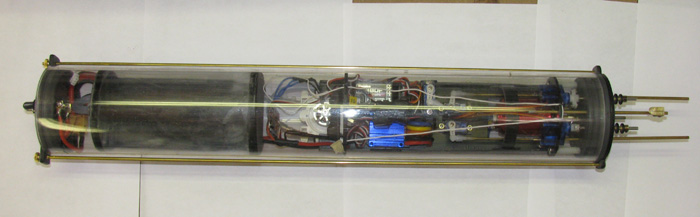
Ok, i pulled the sub out the loft and i noticed a few things.
The ESC for ballast pump looks quite elaborate
Also the central chamber with the ballast bag has 3 holes in it towards the rear chamber, should these be sealed or is this actually some sort of RCABs where the compressed air from the ballst chamber can escape into the rear compartment.
The servo pushrods exit the rear bulkhead with a T joint with a rubber cap sealing the offtake, are these used to push grease into the tube sealing the internal shaft.Comment
-
The pump controller looks fairly straightforward, looks like it's relay based. If the tank vents to the rear chamber, then don't mess with it. I'm assuming the end cap of the rear chamber is held in with rods, or some other mechanism to prevent pressure popping it off.Comment
-
No nothing securing the rear bulkhead ?Comment
-
As I suspected, the air in the ballast section is intended to vent into the other sections. Given that, I would recommend installing some means of making sure those end caps will not come off when the bag is full of water.
Is there clearance to add a cross member in the hull....actually two, one at each end of the dive module? A cross member is one way to help keep everything in place.
-JeffRohr 1.....Los!Comment
-
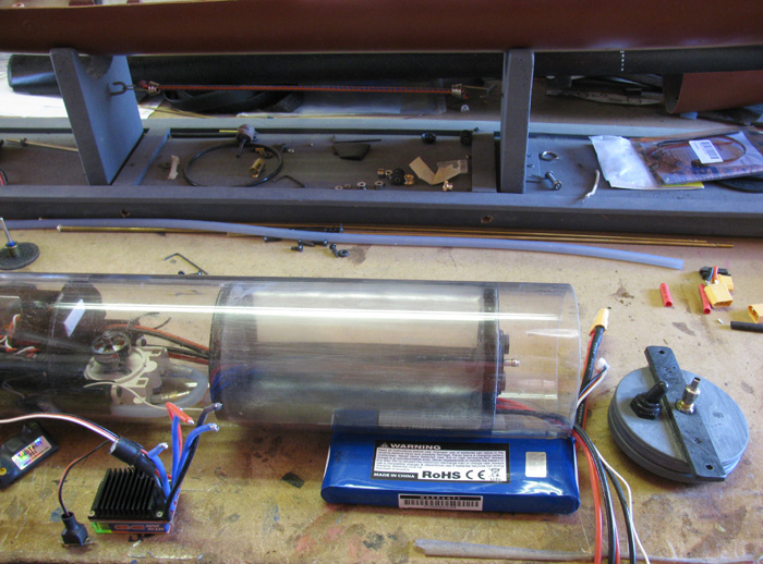
Looking at my cylinder above, you can see the two rods that hold the end caps from popping out when pressure rises during ballast bag inflation.
In the hull, I cut small 1/8" notches in the top of the frame sections for the rods to sit in.
The rear of the cylinder rests against a frame so the cylinder can not slide rearward.
At the front, I have two tabs glued not quite straight across the hull but about 1/2" down so the thumb nuts have some place to go with out hitting the tabs.
The rods fit in to the frame notches with a little room to move.
I didn't want them to bind when the hull and frames contract from the cold water.
Another note.
The tank inside my cylinder for the ballast bag is vented at both ends so as the bag fills the air can move through out the cylinder.
The bag tank is to contain water should the bag leak.
I can still bring my boat back without water getting to the electronics.
Also by using the entire cylinder for the pressured air, the pressure over all is reduced.
Reduced pressure means the pump does not have to work harder to over come the pressure build up.
Less pressure build up inside the cylinder means less pressure on the through hull seals.Comment
-
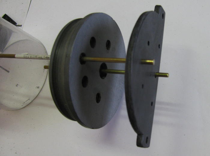
Here a two photos showing how I made the cross bar for the end cap retaining rods.
This is the front cap.
You can see the Schrader valve going through the strap.
The strap is made up of three layers of 1/16" sheet plastic glued together.
This photo is of the rear cap.
There is a lot going on.
The plate is used to not only have the retaining rods to hold the cap but the retaining plate also holds the O-ring seals and the shaft cup seal.
This was one of those thing I wanted to try to see if I could make it work.
I wanted to eliminate all the O-ring seal fittings.
Works just fine.
Not in the photo are the stainless screws that hold the plate to the end cap.
They are place to be between each seal and hold a slight compression on the seals.
Remove the screws & Plate and I have access to the seals to regrease or replace.
Comment
-
thanks guys i think i have enough room to fit cross members, seen as how the air vents from the centre section into the aft chamber whats the reasoning behind the 2 bulkheads making up the centre ballast section being bolted together ? and both having an o ring, is this too ensure no movement so that when the ballast is emptied it works to compress the ballast bag along with pumping it out. on your end cap next to the valve is a switch, i have such a switch as well with 6 terminals, are all the power circuits routed through this ?Comment
Comment