Exactly what Ralph said. Also, if air cannot get out from the deck, it will need a path so it can escape. Putting in half round cut outs on top of those braces will give air a way to move out of one section to another that may have an opening to let air out. As a general rule it needs to be 1/8” (~3mm) or larger to break surface tension.
-
If you can cut, drill, saw, hit things and swear a lot, you're well on the way to building a working model sub. -
I see what you guys are saying now, thanks, and it’s a good idea, but kinda impractical at this point. My thin, fragile frames are already starting to break off through normal handling. Messing with them more now would remove only a negligible amount of new material at the expense of more breakage and trouble. I can and will take a shot at removing a little more from the wide, sturdy frames though. They can take it.Comment
-
Jeff, it is only suggestions, you are n the captains seat! We are learning from you.If you can cut, drill, saw, hit things and swear a lot, you're well on the way to building a working model sub.Comment
-
Jeff, when the deck pieces are installed on to the frame base, will the decking strengthen the frame members?
I would think they would.
So it sounds like you have removed as much material as you can.
You have gotten me where tomorrow, I plan to look under my Gato deck to see if there is more I can do t lighten it.Comment
-
Tom and Ralph, I bit the bullet and did my best to follow your advice, very carefully attempting to at least BEZEL the under-edges of all my cross frames using a coarse sanding stick, since there really was no way I could round off those pieces. Fortunately I only broke off one I had to re-glue.
This really didn’t eliminate any weight, but it may indeed, as you say, help to migrate air bubbles at least a leetle bit, and if so it was worth it.
And yes, Ralph, I have no doubt that once adhered, the frames and the PE pieces will very much strengthen each other.
Thanks, guys.
So now I move on: onward and downward!Comment
-
The PE will strengthen the frames.
I knew you had a plan!
And about the beveled edges of the frames.
The Wright bros did water testing of various shapes when they made thier wing spar.
The found the a square spar with slightly rounded corner edges was more aero dynamic than a round or even a foil shaped spare.
The foil shape becomes more aero dynamic at higher speeds but the Wright brothers plane would not reach those speed.
A slight bevel or rounding will help shed air bubbles better than a square corner.
A square corner causes a low pressure on one side to the square edge and collects air bubble.Comment
-
Taking a page from Paul Crozier’s playbook for Wahoo, I have putty-filled the many tiny holes in the small portion of Harder’s foredeck not covered by the forthcoming “all-teak” PE overlay. I believe this mass of tiny perforations—as molded into the kit’s deck—represents a late- or post-war deck mod. Paul’s research shows far fewer holes in Wahoo’s metal deck than those shown in the kit parts, and he has altered his deck accordingly. My more limited research appears to show no perforations at all in that area of boats with full-length teak decks, so I’m just filling ‘em up.
JeffComment
-
The lights are always burning at the Porteous yards these days! Good work.Comment
-
Thanks, buddy! More to come soon!Comment
-
Finally.
It took a new job, a move of a thousand miles, and a year to clear and stow the clutter, but my workshop is back in business.
After taking a thorough look at Trigger I decided I needed to take a second look at the limber holes. Trigger is a Mare Island boat and has the Portsmouth hole pattern whereas the Revell kit does not. I designed a part that I could theoretically cut into the same area on the kit to match Silversides Trigger's still extant sister. The parts I got back are thin styrene and needed quite a bit of bracing and strengthening to hold up to anticipated sea pressure and general abuse underway. There is some tweaking to do yet but I feel this just might work.
Kit part over my installed part
The thin part flush in place. It is much thinner than the kit plastic so it has to be built up from behind.
Some dimensional Evergreen and epoxy keep things sturdy.
I was limited by what the vendor stocked in polysteyrene and while my parts are satisfyingly scale thin, they are also fragile so I ran thin brass rod along the bottom of the inside goobered along it with 30-min epoxy and micro-balloons. CA glue was not up to the job.
Deck isn't on right in the photo but you get the idea. I will be approaching that deck project here shortly. I have the Photoshop Illustrator file I sent to the vendor (Ponoko) but I make zero claims to it's accuracy. Its a close VISUAL match to Silversides Trigger's sister in Muskegon. PM me if you want itComment
-
Wow, Tom, I am just so happy to see this progress. Good on you! A good feeling, isn’t it? Keep these reports coming, wolfpack mate!
Suffered a deck setback myself today. The PE overlays I’m using are from Oto Gerza out of the Czech Republic. They’re gorgeous! But I just discovered that the teak deck sections I have from a competitor, which I was going to use on the scratched deck extensions I’m adding which are not covered by Oto’s pieces, don’t match them in width or look so just won’t work for my obsessive tastes. Went online to order more PE from Otto, and I found out two important things:
1) He’s upgraded the original set I bought to now include the very deck extensions I’ve scratched (and much better than mine, obviously) as well as the exact matching teak deck to go over them! So I WANT IT! But it means I’ve got to pull off one of the major PE pieces I’ve now already installed! And...
2) Good man that he is, Oto has temporarily shut down his PE model parts business in order to make protective gear for medical workers during the pandemic, and won’t be taking orders again till next month.
SO, all work now stops on the deck—which had been required to be built in a certain order—and now I move on instead to hull and/or conning tower work while I wait. Actually, with the looming SCR project getting ever closer, I likely won’t be spending much time at the workbench the rest of May anyway...Last edited by jefftytoo; 05-06-2020, 01:42 PM.Comment
-
Nice!
B^)Comment
-
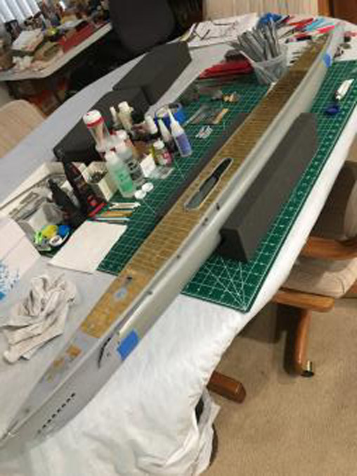
Visible progress, though this shot is misleading: a large piece of PE decking—the second section aft of the bow—will later be pulled off and supplanted by a more accurate replacement yet to come from Oto Gerza in the CZ Republic; a piece which includes wonderfully accurate, much-needed “teak”-covered deck extensions* (parts which I’d only moderately successfully already scratch built but not yet attached, thankfully). All that PE decking is currently held on by a thin layer of 30-minute epoxy (Tom Kisler’s great idea), but will be permanently affixed later by adding thin CA to the deck frames from the back as well.
The superstructure itself is held in place by a tongue-and-groove at the bow (completed) and a magnet assembly under the turtleback aft (half-completed). More magnets may be required amidships—not sure at this point.
(I see the Forum has rotated my iPhone photo again—sorry about that!)
Now all this pretty much comes to a halt as I slowly embark on producing the next issue of the SCR.
*I only just found out this new, more accurate PE was available.Last edited by jefftytoo; 05-09-2020, 11:34 AM.Comment
-
How about this, Jeff.
-----------------
Jeff's Gato deck.
Comment
-
Hey, thanks, Ralph!Comment

Comment