Attention all registered users. The new forum upgrade requires you to reset your password as you logon for the first time.
To reset your password choose this option that is displayed when you attempted to login with your username: "Forgotten your password? Click here!"
You will be sent an e-mail to the address that is associated with your forum account. Follow the simple directions to reset your password.
If this is your first visit, be sure to
check out the FAQ by clicking the
link above. You may have to register
before you can post: click the register link above to proceed. To start viewing messages,
select the forum that you want to visit from the selection below.
Hello again,
Today we’re delving into the black arts, what I mean by that is its time to build a new contra rotating gearbox. I mean new because I have attempted this before in the form of a differential system that was to take a single input shaft and transfer that energy into two contra rotating shafts. This time I’m going for a different design, one that allows proper gear alignment and discards of the heavy metal gears. It also will be driven by two motors as opposed to the single big motor and will be easier to install and remove for maintenance. I don’t know if it matters, but the real Jack propeller shafts were driven from two separate turbines, so I guess this makes my new system more “scaleâ€. Although this system is very complex at its very roots, I want the end users to be swearing as very little as possible (with my name in there somewhere) when they are doing maintenance on the mechanical section of their USS Jack model!
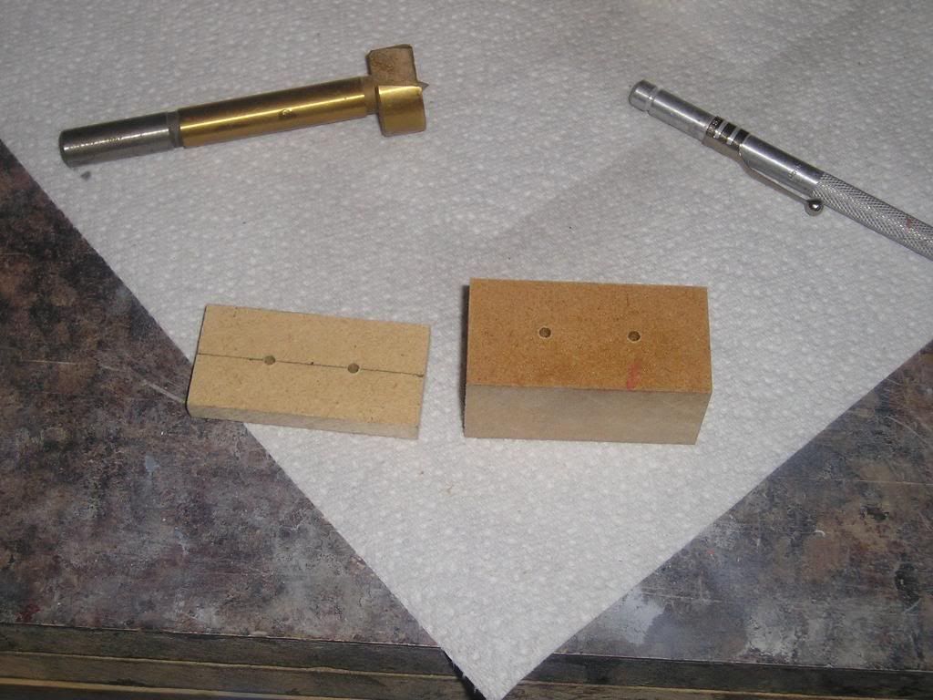
To start out I selected MDF as my building material again for the main body of the gearbox. I actually was going to use urethane plastic poured and shaped into a block, but for some reason I couldn’t find any of the melamine that I use for that molding process in my garage, it must be outside under two feet of snow maybe. So, I just cut up some 1†and ¼†thick blocks of MDF on the table saw.
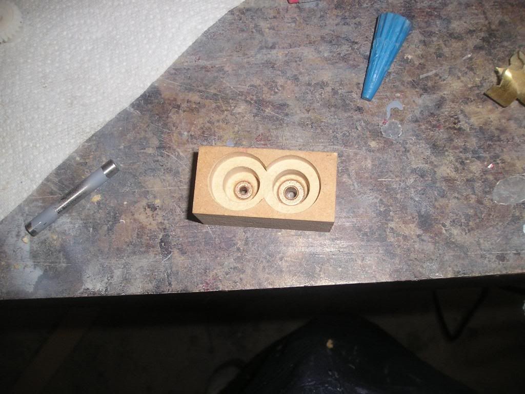
With both pieces temporally glued together , I drilled small pilot holes through the whole thickness of the blocks where axial center of both gears would be
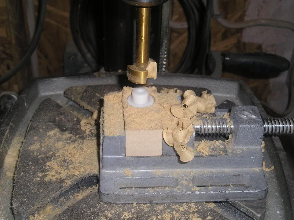
All flush bottoms boring were done using Forstener bits once again. The starter pilot points on the bits followed my initial pilot holes beautifully as I worked my way through the different stages of drilling. Believe it or not, I think I used somewhere in the neighborhood of around 15 or so different styles and sizes of drill bits. Lots of power tools were used in the making of this little gearbox!
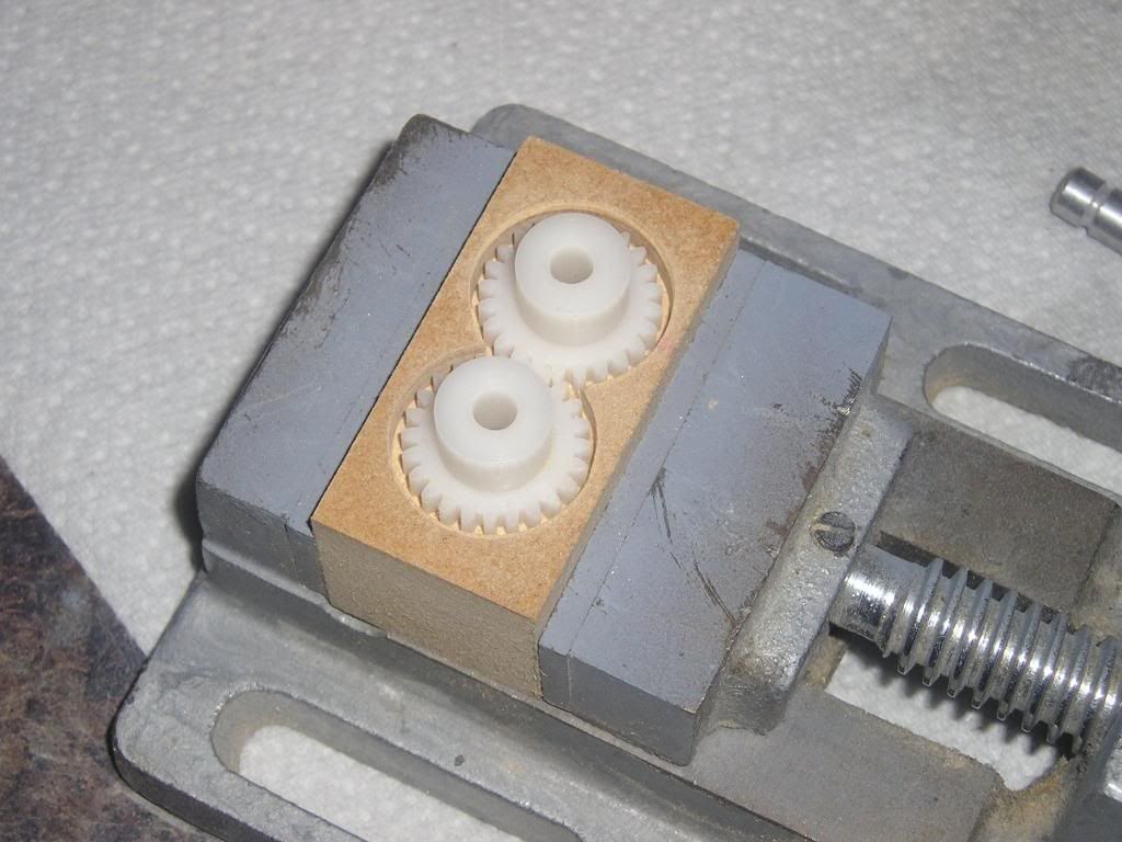
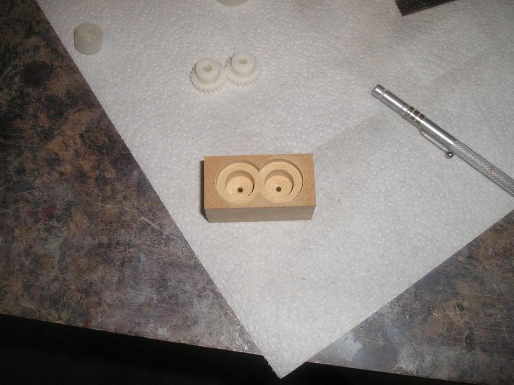
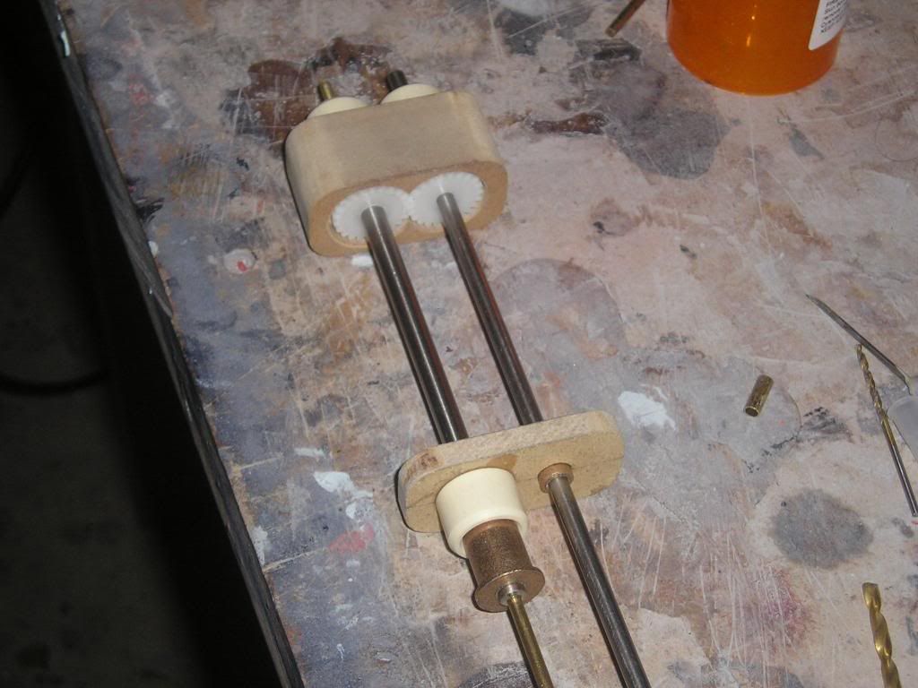
Oilite bearings installed in the bottom;
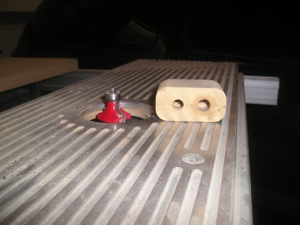
Rounding the edges was done using a ½†roundover bit in one of my routers installed in a router table…not much to say here.
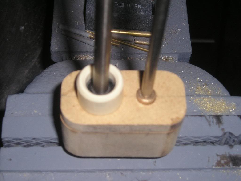
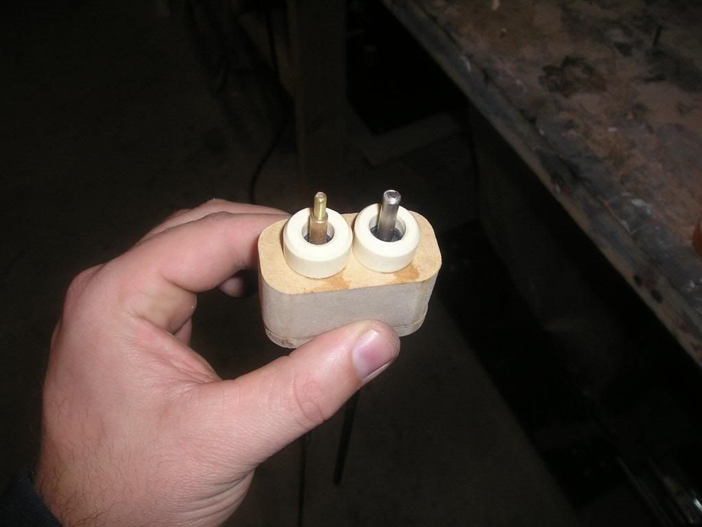
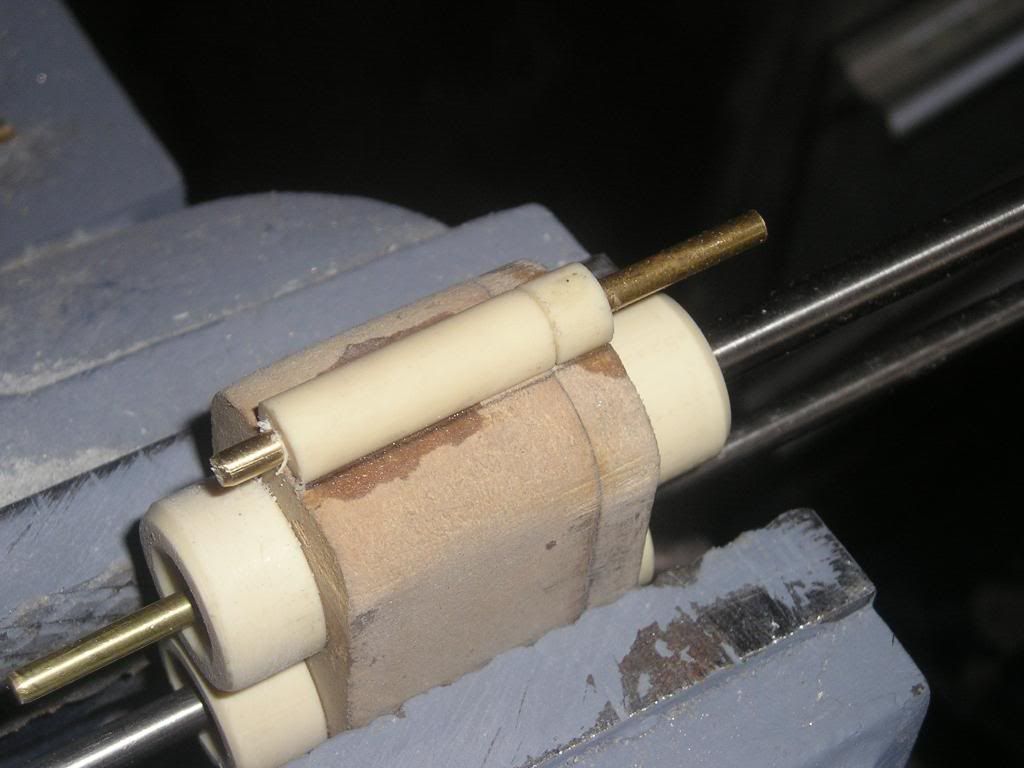
I want to make this as a sealed unit so that the gears are not affected by hydraulic affects (water hammer) from squishing water in between the teeth so I am making seals for each shaft touching water. I am using U-cup seals (rotary lips seals) for this application. They basically get wedged inside a cylinder right in front of a bearing and are then kept in place using retainer bushings which are silicone into place. All the seal part excluding the u cups were machined from Alumilite on my wood lathe. It would be better and more practical to use a metal lathe and I do in fact have a brand new one, but I still have to grind all the HSS tools to shape, so I just threw these on the old wood lathe…lazy!
Ok I’ll stop there for tonight, but there is lots more to come on this fun little project…
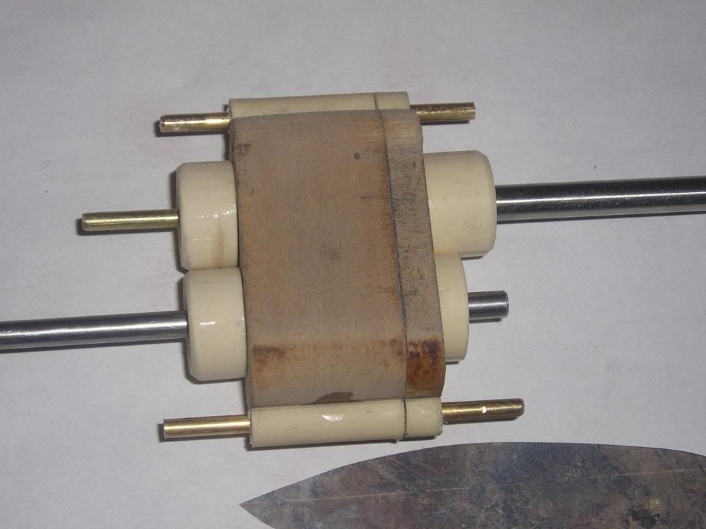
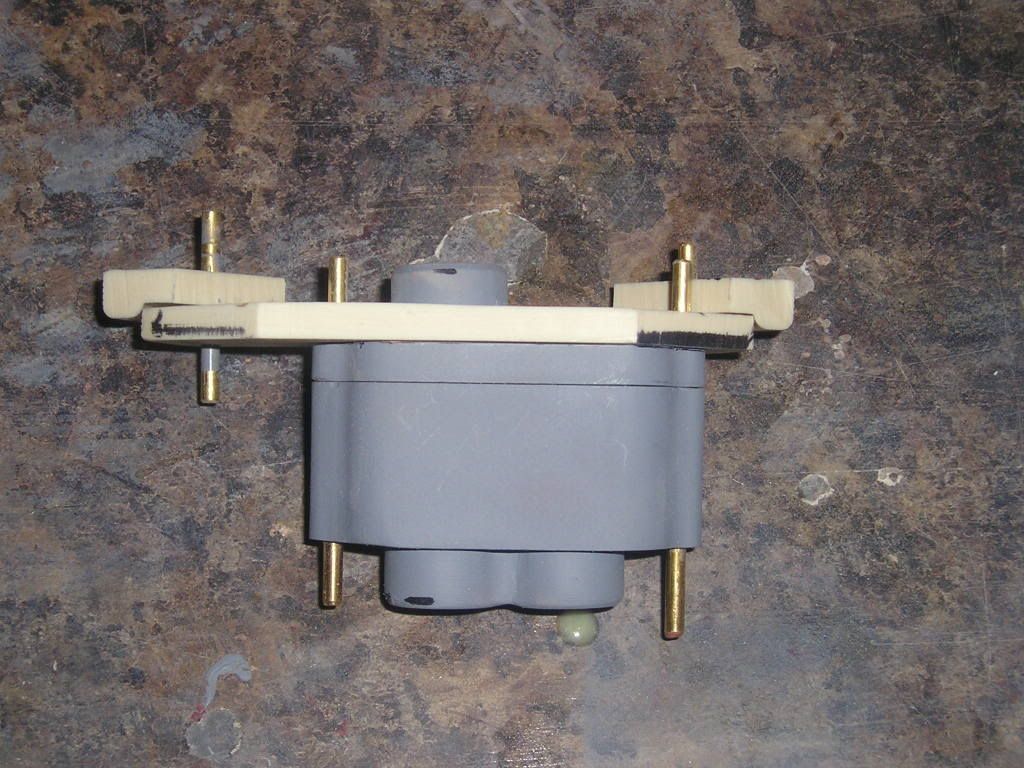
To keep this sucker held together and to have a way to mount the gearbox to mount inside the hull I have chosen to install two stud housing on each side of the gearbox. These will permit the two box parts to be attached firmly to each other and a bracket, all perfectly registered to one another.
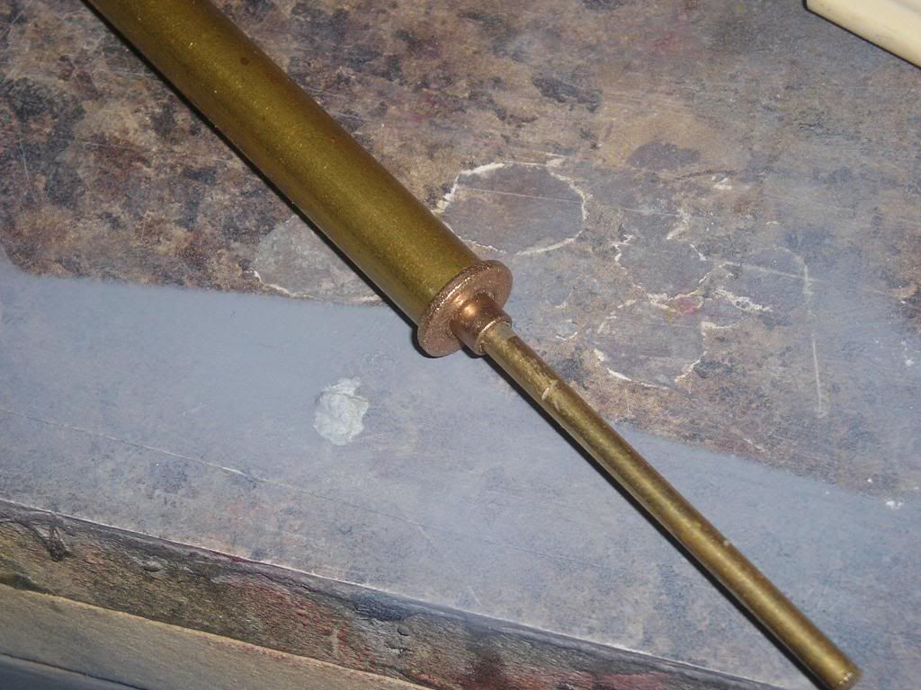
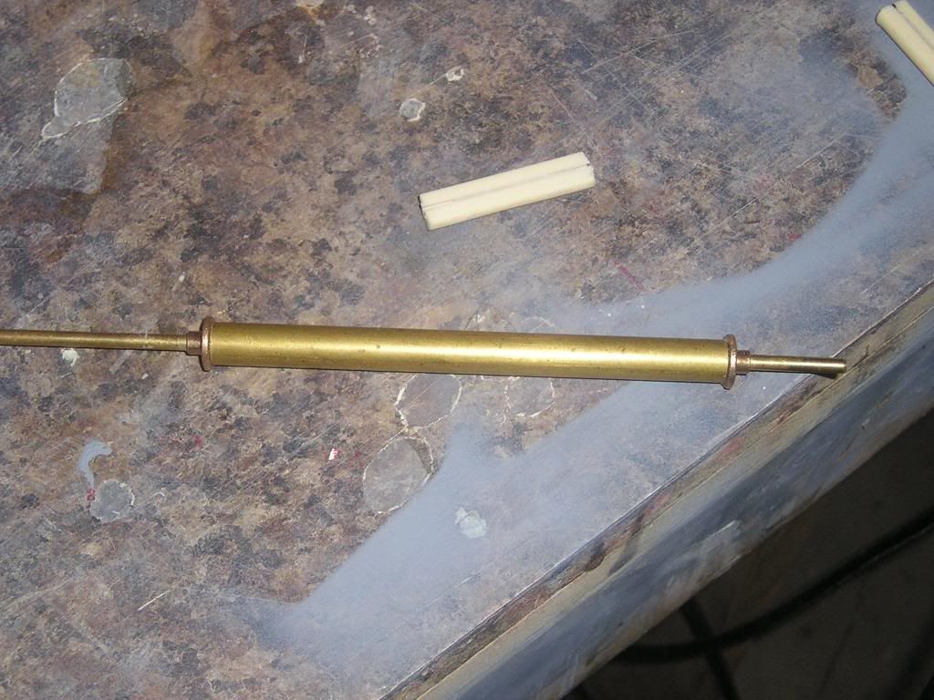
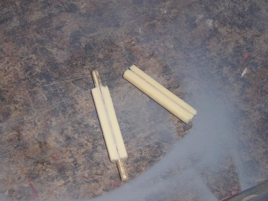
I could have made these with wood dowels and machined holes in the middle of them but the diameter wouldn’t fit into the chuck I presently have on the wood lathe, just too small. So I went a different route; I used some brass tubing that had the internal ID that wanted and fit a brass bearing into the bottom with a 1/8 rod going all the way through. This was in turn held steady in some modeling clay. Keep in mind that all brass surfaces inside my little mold here was brushed with Vaseline as a mold release. Alumilite was then poured in the top and then another bearing was slid down ensuring the shaft was perfectly centered in the tube. The whole thing was placed in the pressure pot while it cured. Finally, to remove the new plastic dowel I fist punched out the 1/8†rod using a hammer and smaller diameter rod. The plastic itself was pushed out using a smaller diameter bolt on one end with the bearing pulled out, and the other end of the tube’s lip on the other jaw of my vise. I simply cranked the vise until almost all of my plastic dowel was exposed…voila! The dowel itself was put into the vise length wise with a brass rod re-installed, and I filed down material until I almost hit the brass rod…this gave me a flat surface to mount to my gearbox.
The stud housings then had CA wick’d throughout the joints to hold securely into place
This basically finishes the construction of the gearbox itself, now onto the surface finishing (fill, sand, and prime, repeat until happy!). I suppose the advantage of building mechanical parts like this is that you don’t have to go too crazy with the final finish as opposed to a propeller or any other exterior finished master pattern.
Just some minor small fills with some red glaze and this part should be done]http://i171.photobucket.com/albums/u319/Rapperkiller/CopyofP1011471.jpg[/img]
Next: To figure out and build some sort of bracket to hold this bad boy in place!
Joel
very nice, I like the hands-on report.
This will be the master fro some cast, right ?
Or will the whole be mounted in the dry compartment ?
Thanks Ronald,
Your right, these are all master patterns for use in making a mold and then casting urethane plastic reproductions, the seals on it to keep just the gear compartment from flooding with water and robbing power, hopefully it all works according to plan!
Hello,
To finish things off with the gearbox assembly I need something to hold the gearbox in securely to the hull. There are prerequisites that have to be incorporated into the design;
1. The gearbox itself has to be able to slide forward easily to allow for maintenance on the box
2. The bracket and box have to be easy to install
3. The bracket itself has to be removable to allow for easy maintenance in the stern cone of the boat (linkage adjustment, etc…)
4. All the parts herein have to be easy to mold and then reproduce
Number 4 is 80% behind my reasoning for redoing all my molds for the Permit. I have to make things easier for myself if I am to keep reproducing these kits so that I don’t get discouraged from the amount of work or screw up from my poor original mold designs.
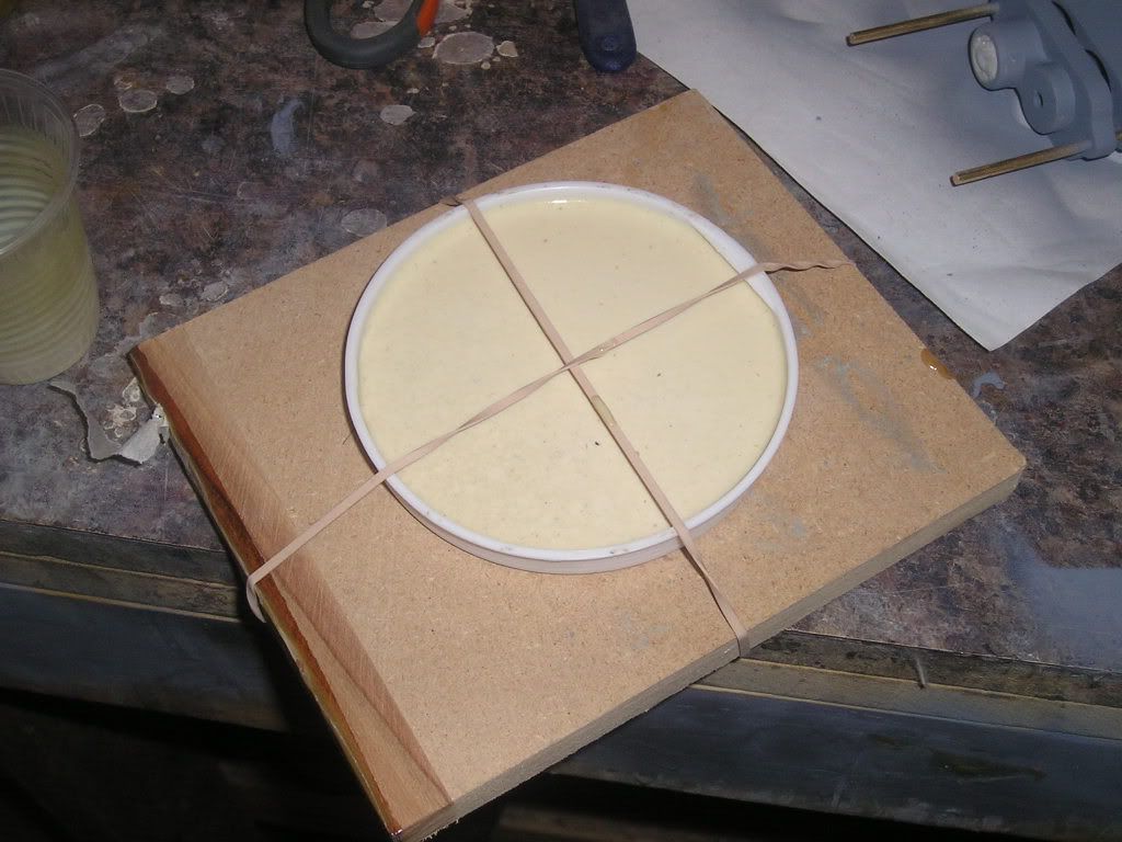
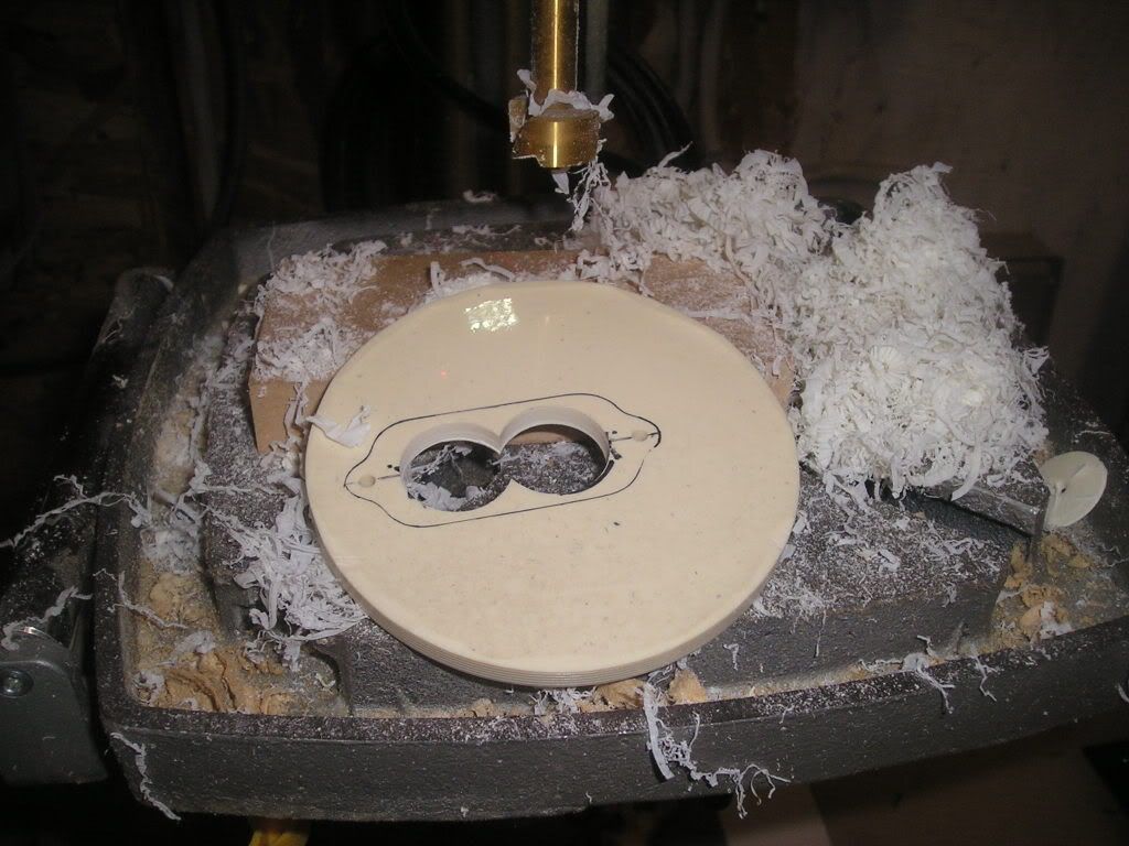
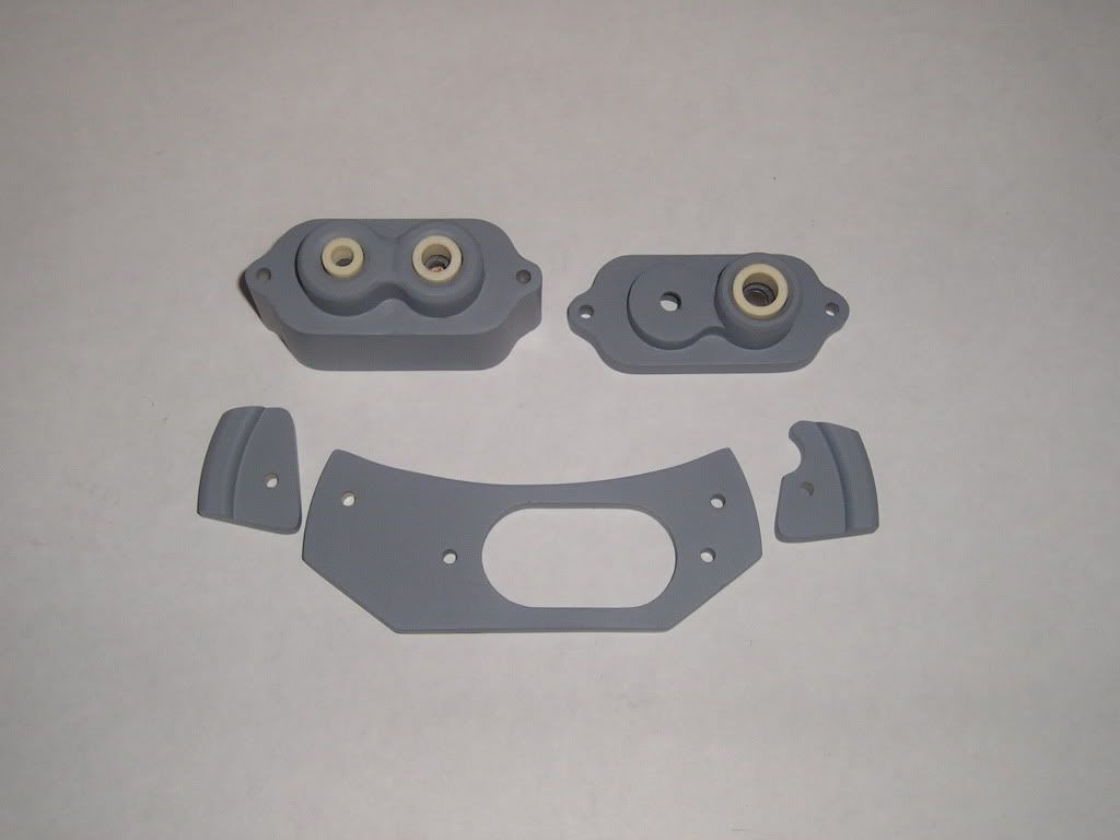
My pattern material of choice is Alumilite poured into a mailing tube plastic cap that works very nicely as a form for the shape I need
A center hole is drilled for my main starting reference point for mounting the box
Forstener bits are used for boring into the material with out worrying about drill bits catching and chipping out the material
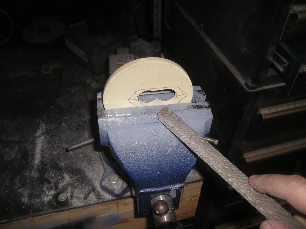
The inside edges are filed down to give a nice oval shape
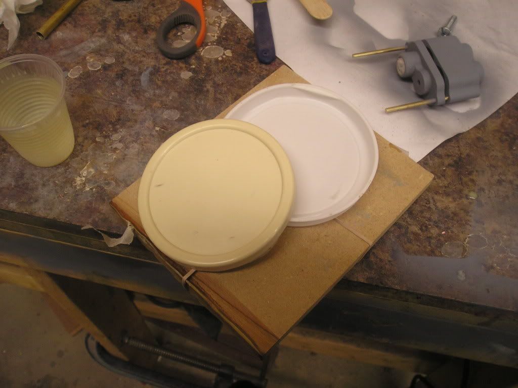
I make sure everything fits before going to the next step;
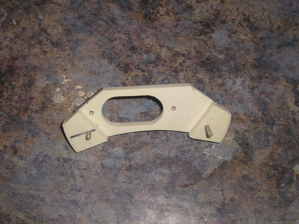
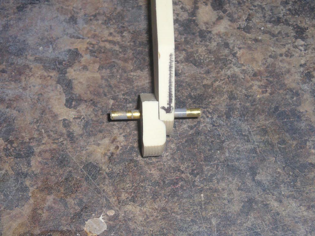
Using the scroll saw I then cut out the final shapes for the bracket. The two brackets holing brackets were also cut out from the plastic disc. Notice how the main bracket fits beautifully into the lip that the mail tube cap/mould provided around its outside edge. The Two small mounts will be the only parts of this glued directly to the hull… so that the main bracket can come right out with the box
Just a minor update here to show that I am still plugging away at the project here.
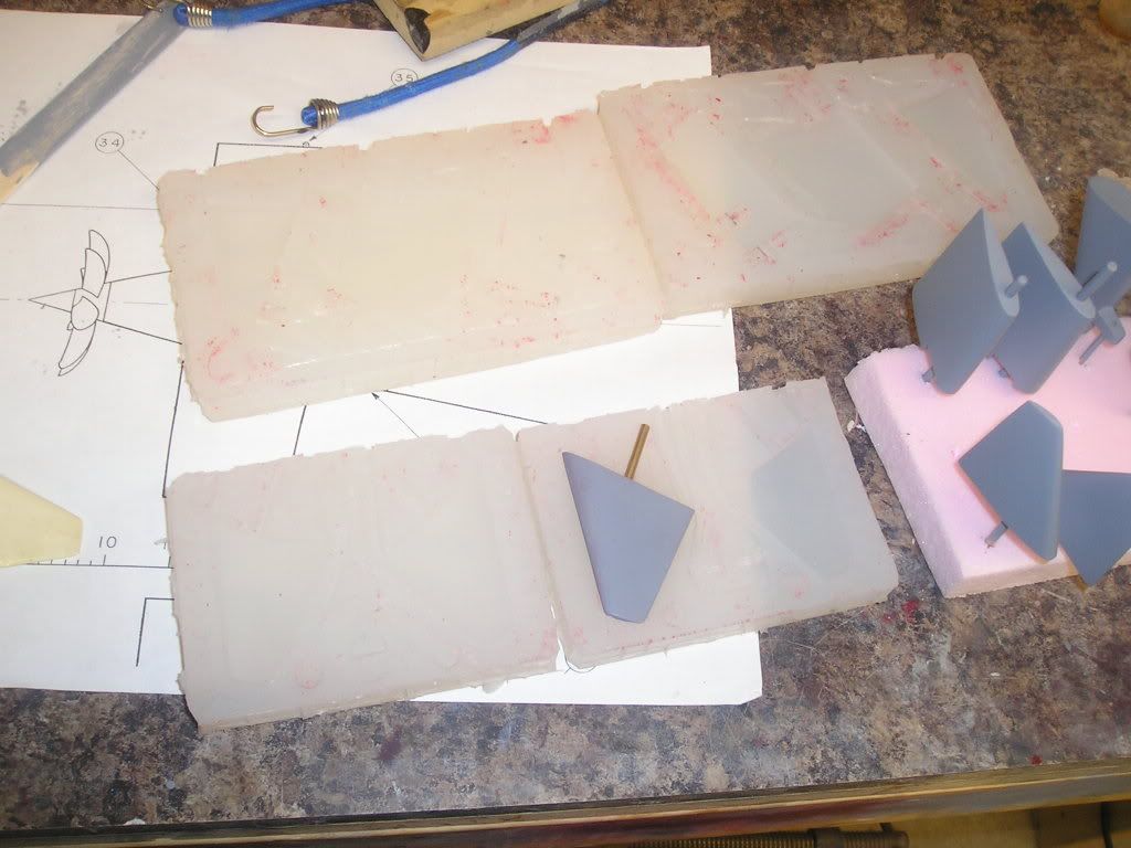
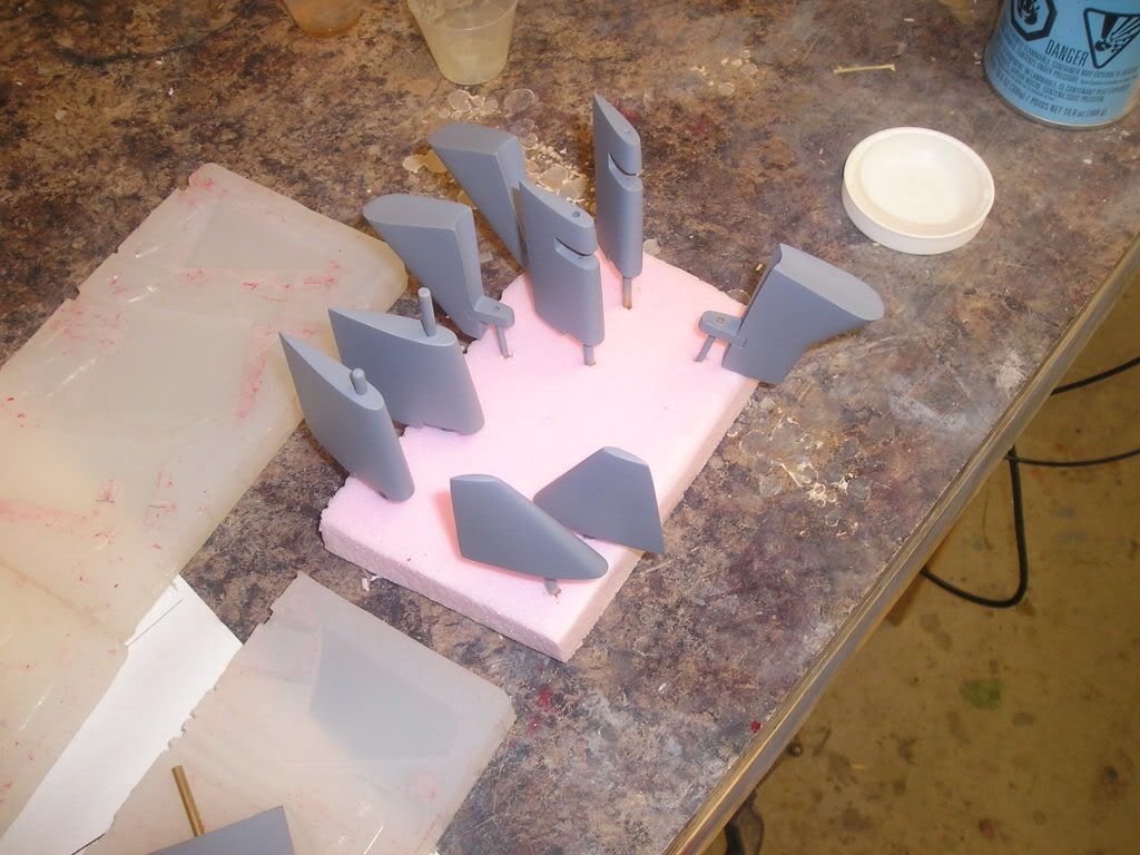
Intermediate molds of the appendages were made so that I could have two of everything, so that when when pouring replicas I only have to cast once instead of twice because I hate wasting time casting! This time around I'm using Smooth-Sil 920 as my rubber moulding compound. I'll have to say I like the stuff. It feels tough and the gallon kits I have bought are more cost effective than the previous rubbers I have bought. I also like the translucent effect of it too. I have also switched my choise of modeling clay to some professional stuff over PlayDoh. It costs more but at least it doesn't shrink and pulls away fom the cured silicone very well.
Appendages drying in primer and waiting for final sanding to achieve a nice consistent surface texture;
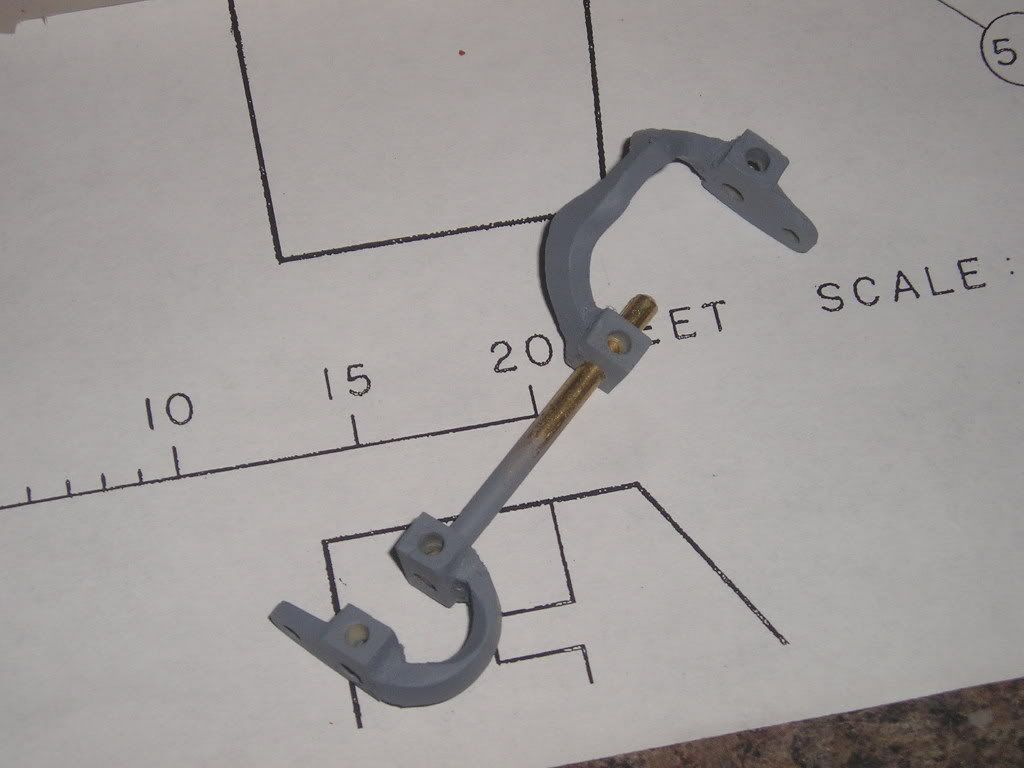
Here, also is the new bell crank system in the rough that I have made for the rear control surfaces. These will increase the efficiency of the install for the modeller, just plain old better design with better aesthetics! Dont' be fooled, the large crank is a little different than the pic indicates, it's a pure optical illusion a la Manowar Copperfield.
Do you have any more pics of your contra-prop setup that show how the motors will connect to the gearbox?
I see two gears side by side and the box with two shafts on the motor side, then one shaft going to the props. I assume there must be a solid shaft within a hollow shaft going to the props, but I'm having trouble visualizing how the two gears on the motor end are translating rotation to a shaft within a shaft on the prop side of the gearbox.. Are there other gears inside the box that are not shown in any of your currently posted photos?
Steve
Hi Steve,
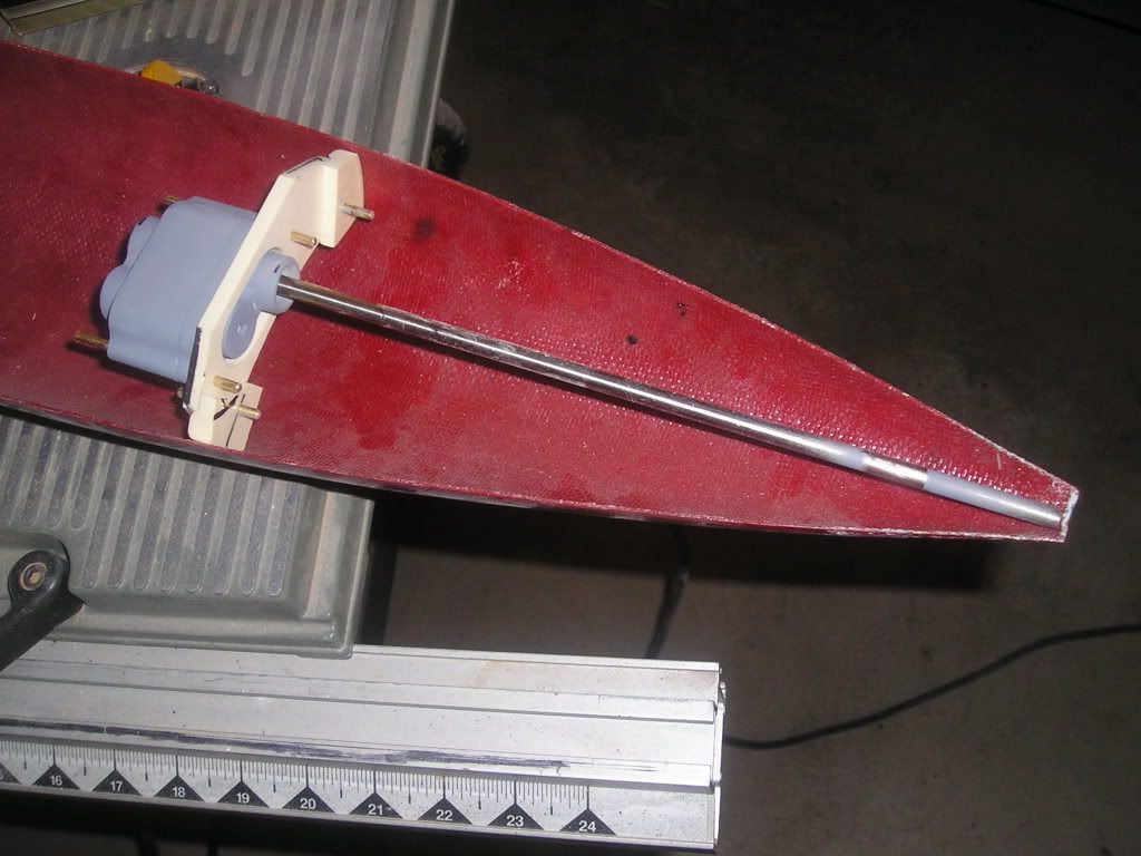
I am at work at present so i'll try to post a pic when I get home later. I can explain how this works though. There are two motors driving this whole thing. Both are coupled to their repective drives using dumas dogbones. One shaft is directly attached to the inner, smaller diameter shaft which in turn drives the most aft, small diameter prop. The other motor drives the outer sleave shaft which drives the larger diamter prop. The gears (only two) are there simply as a means of power transmission and they can be any size I want them to be as long as they are the same size as each other. I've made other designs, one of which is a differential system using a one shaft input, this two-motor way is alot simpler.
Thanks Joel. I'll look for the pic after you've posted it.
If I understand what your saying correctly, your set up works like this:
One motor drives the aft prop, using a solid shaft, that passes through the center of the first plastic gear (but is not connected to the gear itself). The other motor drives the second gear, which in turn drives the first gear, which is attached to the hollow drive shaft which turns the forward prop.
If this is the case, then both drive motors are rotating in the same direction (probably counter clock wise when seen from the stern) and not canceling out their generated torque roll. The props are canceling their torquing action, but not the drive motors. Wouldn't the sub still tend to torque roll to one side because of this? Especially if this setup was used in a boat with rather powerful drive motors (something different than the Jack lets say).
Are you going to have one ESC controlling both motors or use two ESCs?
Yes Steve, you have it right on the money for the configuration setup. You present an interesting question as far as torque roll is concerned. I've always thought of torque roll as caused by propellers biting into the water, but you could be absolutely right in regards to motors doing the same. The options were to either use the two smaller motor setup or a large single motor which could in itself cause more roll. I think the best way to see what will happen is to run the system in a finished hull just without the propellers in the water...


Comment