Attention all registered users. The new forum upgrade requires you to reset your password as you logon for the first time.
To reset your password choose this option that is displayed when you attempted to login with your username: "Forgotten your password? Click here!"
You will be sent an e-mail to the address that is associated with your forum account. Follow the simple directions to reset your password.
If this is your first visit, be sure to
check out the FAQ by clicking the
link above. You may have to register
before you can post: click the register link above to proceed. To start viewing messages,
select the forum that you want to visit from the selection below.
Oh a super secret mixture of black and white
he diffrence this time i think is that I used a matte finish for the clear coat and I applied it at a distance shaking it vigorously. It gave it that uneven paint job look that the real things have.
Hey guys, I forgot to mention this, but I am contributing the documentation of the Long sail Permit as an exclusive build thread on Brian Stark's new site to kind of help get it going. Over there you'll find a nice gathering of modellers starting to form who are into the whole spectrum of building. The link for it is below in my signature.
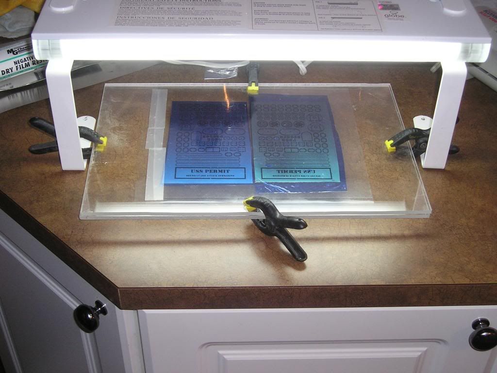
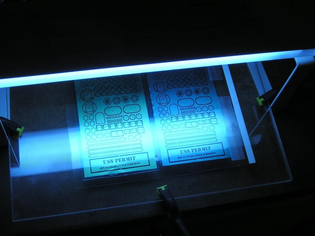
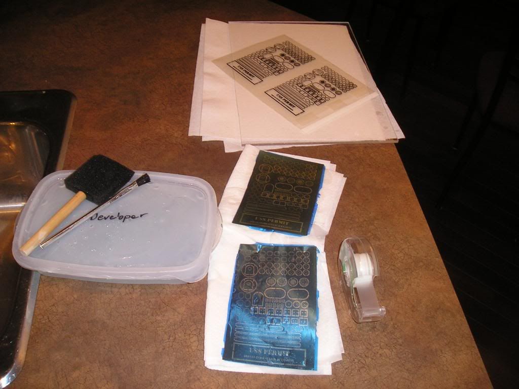
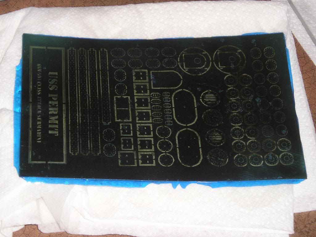
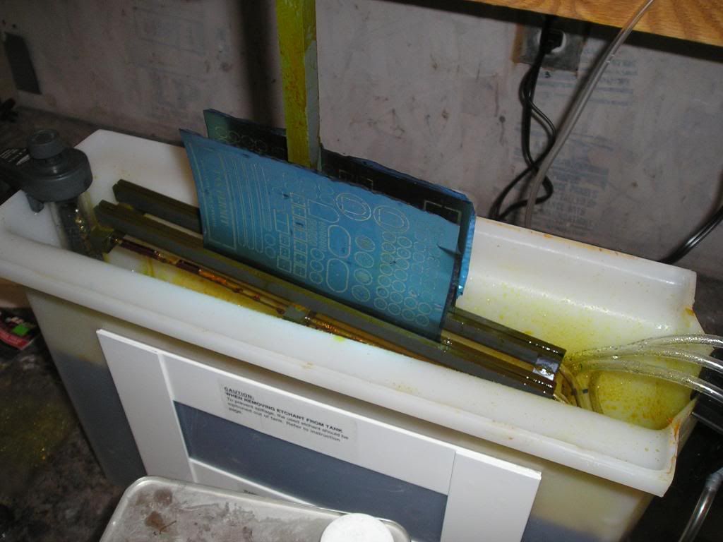
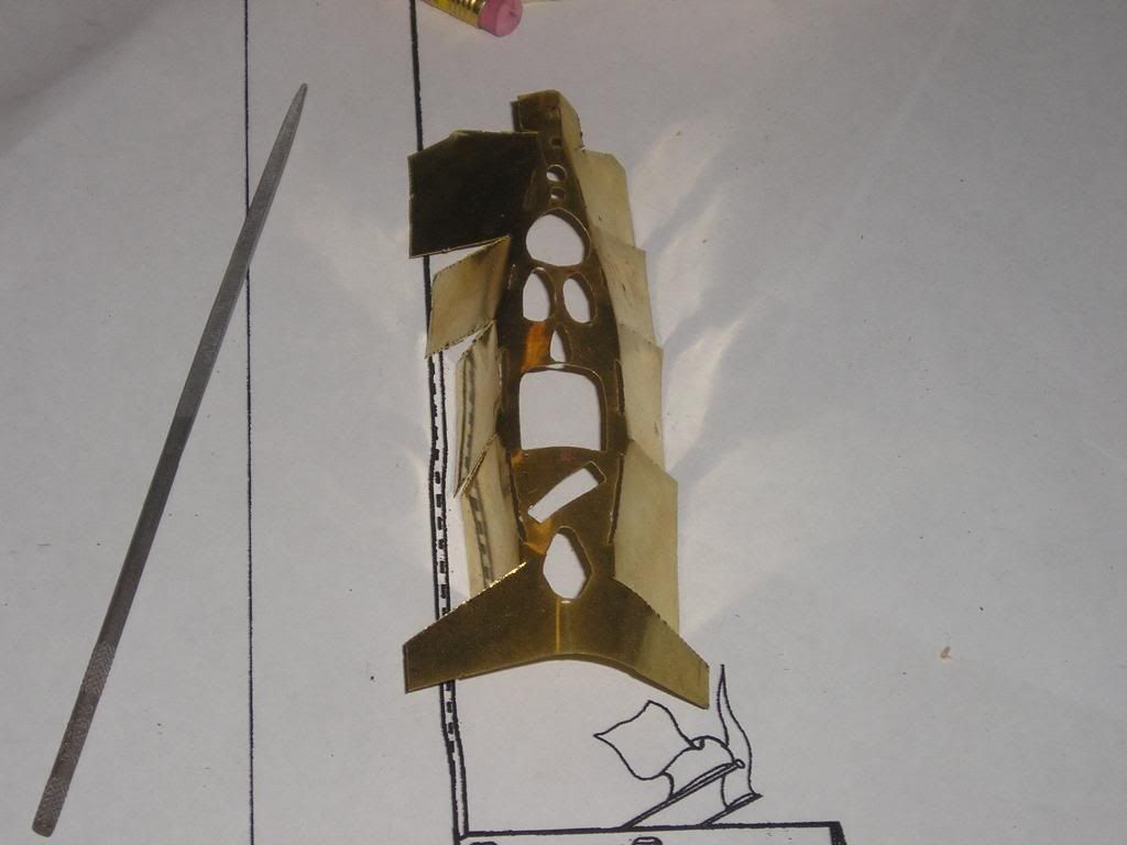
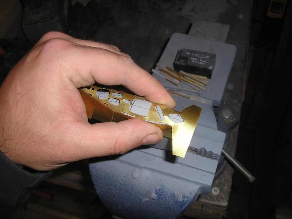
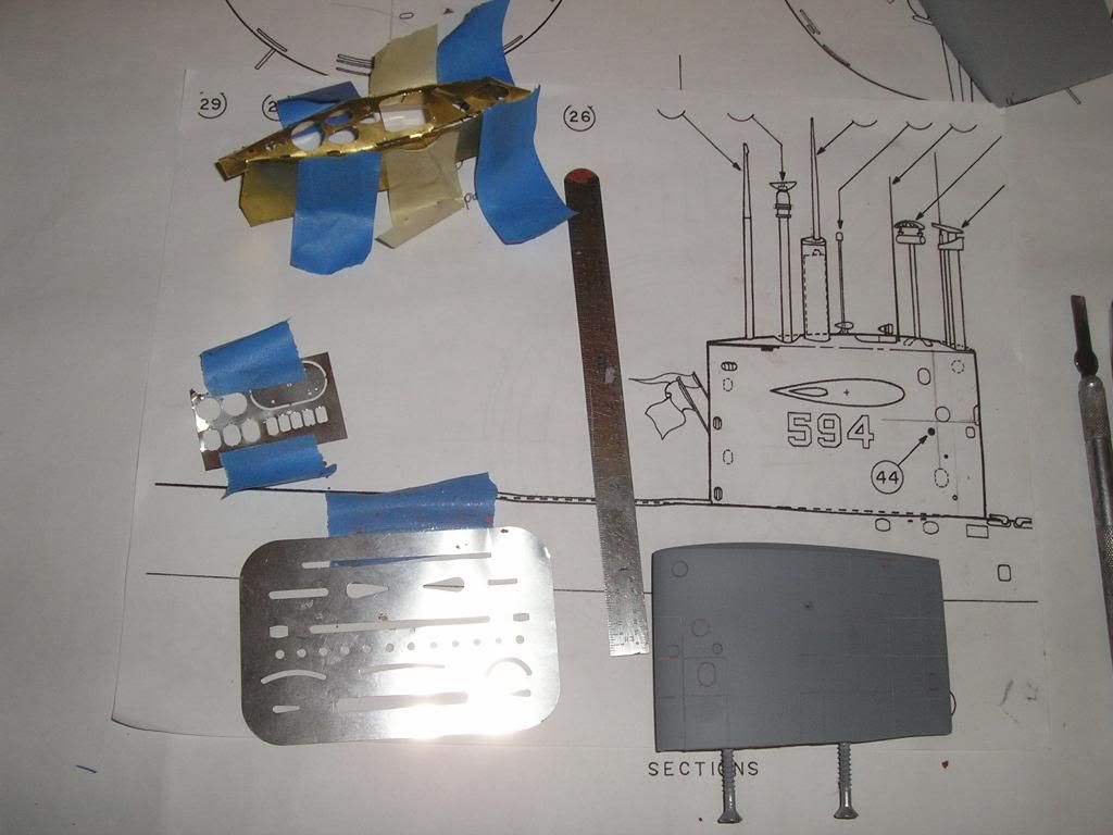
So getting further along here in the build I have decided to once again use photo etched details on the hulls, so I’ve gone out and purchased a larger professional PE system so I can do multiple copies and much larger sizes of PE sets. Yep, it cost lots more than the Micro Mark system but the results will be better.
Now with the help of my buddy Olivier I am improving the lines for all the circles on my PE template. MS paint has very severe limitations when it comes to dpi resolution…
Thanks Brian,
This etching can be somewhat of a black art to get perfect, watch what I do and learn from my mistakes and you won't have to got the pain that I have!
Here's a small update to get you primed up for the weekend.
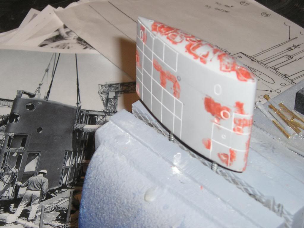
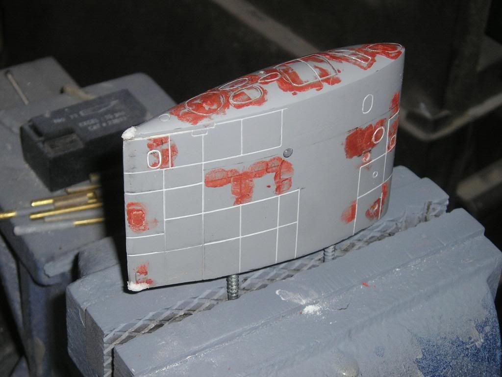
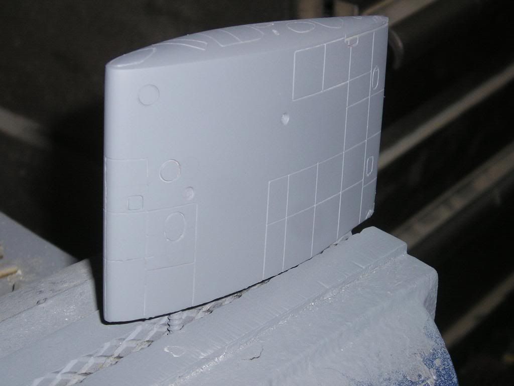
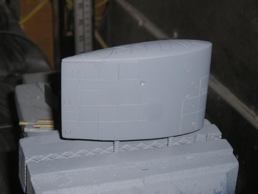
I did some work on the sails, which was mostly sanding and prepping for detailing. Basically all sanding was done with wet sandpaper, starting at 220 grit. This is course enough to remove any orange peel or iregularities from the spraying process. Keep in mind here that my vinyl ester ultra super hard, high build primer is also super hard to sand. But that's cool because that tells me its got some properties for scribing that I am looking for...like structural durability to produce sharp edges in the scribes. Like my hull, the sanding is halted at 400 grit and then it's detail time. Once all scribing is done, I proceed to polishing and then after that I drill out all detailling that will take sunken photo etch detail and then apply the detail itself. I wait until the very end for that because because buffing over PE no matter how thin it is will get caught on either the sandpapaer or the buffing wheel itself.
For the detailing on the top of the sail, I am cheating. I copied the plans and made a PE template directly from it. Notice I have made some modification to some of the shapes if you are familiar with the Permits. These are simply to get closer to what the real thing looks like.
Here is the top of the sail with the detail drawn out on it. I actually scribed the details in later, but I found I didn't spray my primer thick enough. I was digging into wood, and that angered me. So I ended up adding a much thicker coat on and went through the whole sanding process again. Whatever, as long as I get it right.
Hi Lulatos,
There are four prices for these Permit class kits:
Permit circa 1961 is 500$ US plus shipping
Permit circa 1979 is 550$ US plus shipping This comes with towed array fairing, applicable perscopes, sonar jammer, modified stern plane, and towed extraction tube and of course a modified sail with a minisail attached
(Note for these above that a long sail, long hull version will be available for the same prices)
Jack circa 1967 is 600$ US plus shipping
Jack circa 1980 is 650$ US plus shipping (same add ons as the Permit '79)
The reason for the extra cost on the Jack will be due to all the extra parts costs incured..eg. gears, bearings, shafts and of course all the extra time to put thing together.
That's what I am going to start with anyway, it might end up being more seeing how the first few work out.
Just contact me at jstadnick@toromontsystems.com, but I'll take certified cheques too. Just a note though, I am still a few months off before the moulds will be ready to start production.
Good evening,
We’re continuing work on the detailing of the sail (short version) pretty much all day today. A perfect day really to be doing this because I pulled my groin playing hockey the other day and can barely walk, and it’s minus 30 degrees Celsius with around 3 feet of snow on the ground…Ah the beauty of living in Canada, I bet you all wish you were here! At least Christmas is authentic here
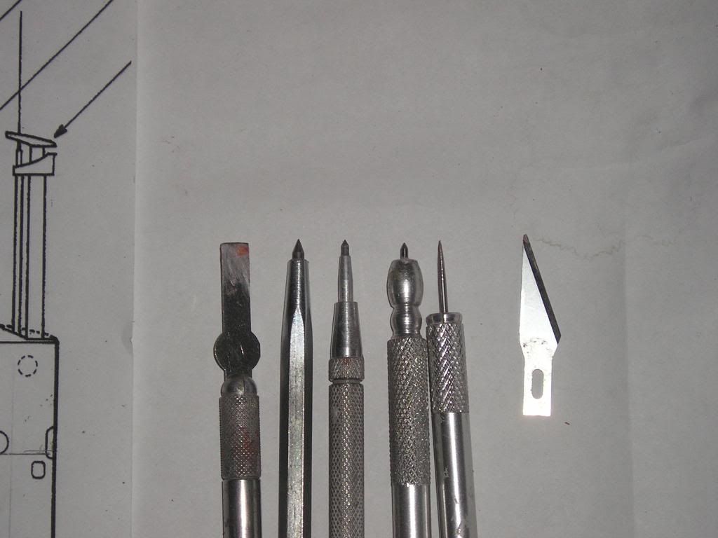
Here are the tools I’m using for scribing:
My favorite tool for the base scribing is the second from the left; it has a good feel to it and seems to hold a sharper edge. You can also go quite deep with it, but I use it mostly for the initial stages of scribing. To its right are various machine scribes that will give me varying degrees of width to the scribe. I use the two tools on the right for touching up and tweaking scribes, and on the far left is a no. 17 Exacto blade, the best thing I’ve found to date for applying air dry red putty for localized filling work.
Here is what I use for straight edges and templates. Thin gauge metal for easy wrap-ability around curves. I think my favorite out of these is the erasing shield as it’s very flexible and can be used for a multitude of uses, including shielding pencil marks while you are erasing!
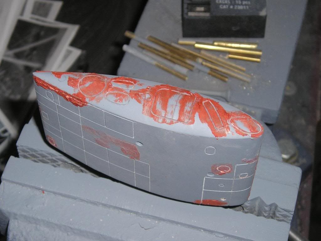
The detailing is actually a multi-step process, it doesn’t look the best when you first get going, but right now is when you want to get line locations and fix misrepresentations. For those that know the Greg Sharpe deep Sea Design plans for the Permit they will notice that I’ve added panel lines and changed locations of some details…all the result of looking at pictures over and over again. One thing I noticed big time between pictures of the sail taken from different eras in the ship’s life is that a lot of these panels and vent locations changed over the years. I started to panic when I scribed some details in certain spots and found them to be in different locations when looking at some drawings, only then to calm down when finding other pics with the details were I put them…whew! Even if my locations were wrong it really wasn’t a big deal to move them. Just fill the old and scribe the new.
All of the red filler is applied after I do the rough scribe and want to clean the lines up. I’ll scribe the line, fill and then use my ultra pointy tool to go through the lines. I’ll let the filler dry and then sand the edges down and then prime to see how my work looks. I find I have to do this about 3 or 4 times already with maybe one or two rounds of this process to go. It sure does work though, the lines come out crisper each time I do this…Thanks Brian for the good advice!
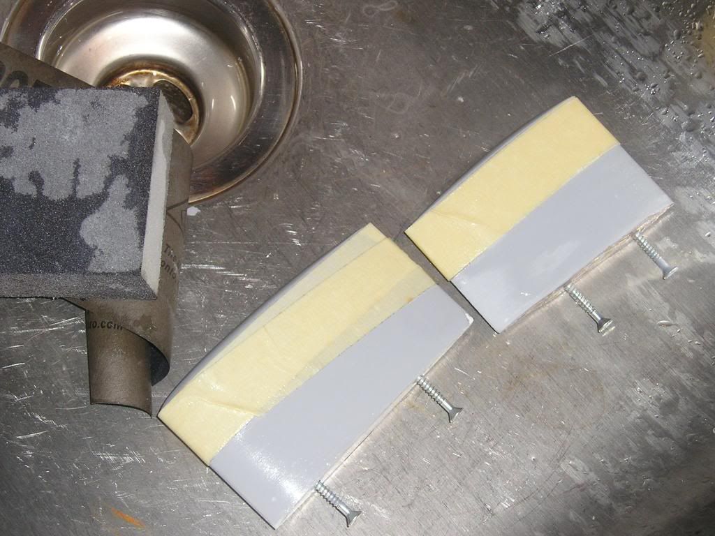
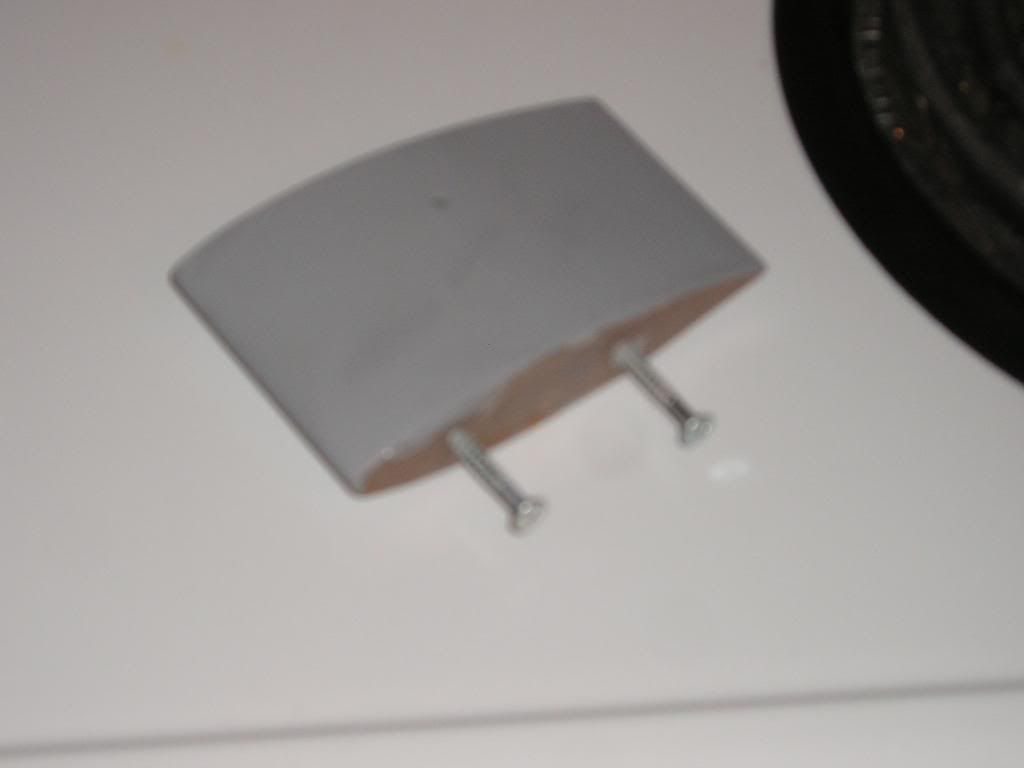
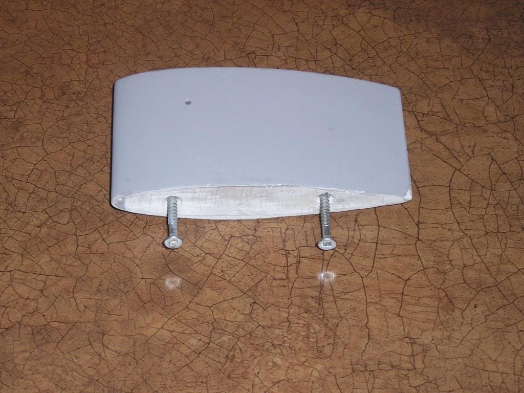
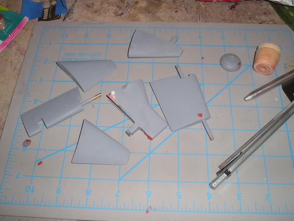
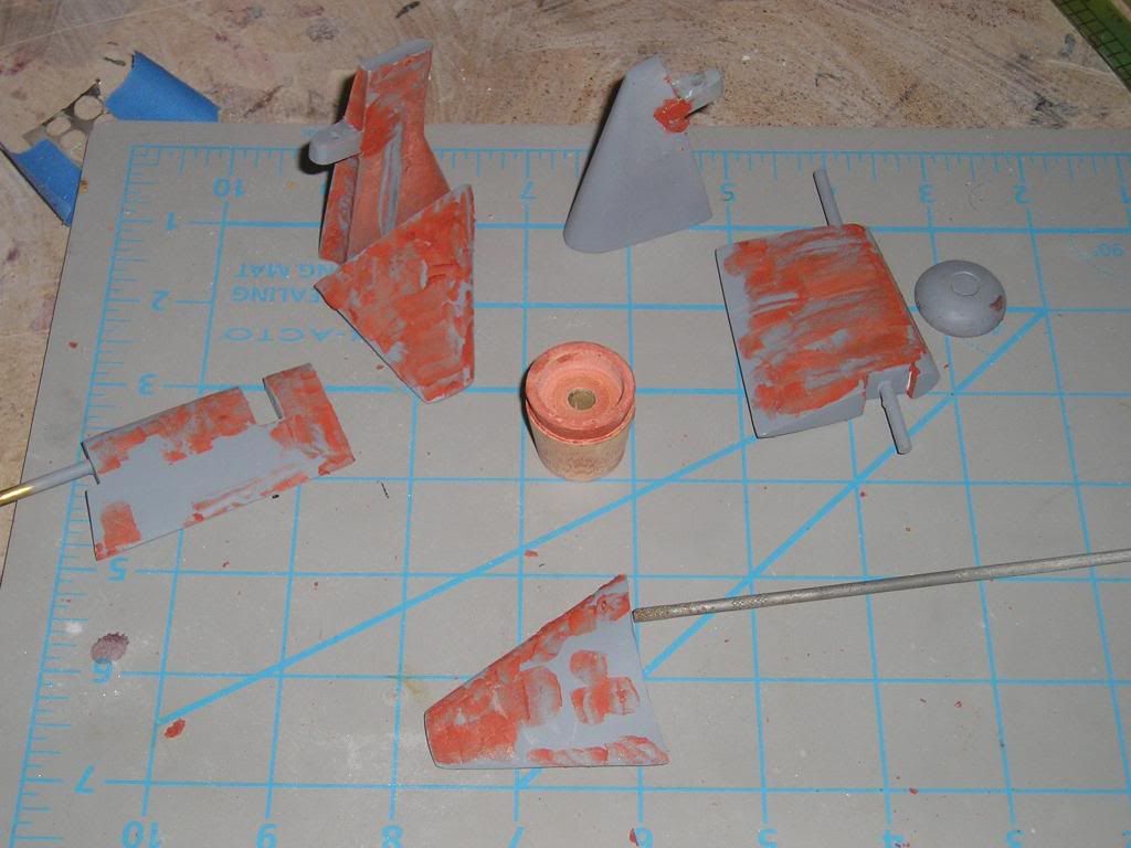
Sometime you have to do other stuff while your putty or primer dries, so I have been touching up and cleaning up all my appendage masters. I have to make new moulds of all these because all my old mold designs were simply not production friendly.
Thanks Kevin!
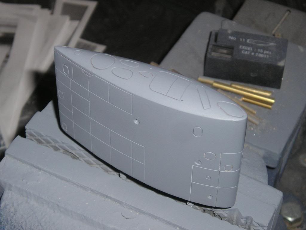
I just felt that the sail according the plan was just too...well, boring. There is other stuff on it than what the plans depict, you just have to look really closely at the pictures to find it. I guess that's what I'm trying to do with this go round, really make a guy look and see what is different (not in the non-scale different kind of way) or added from the plans.
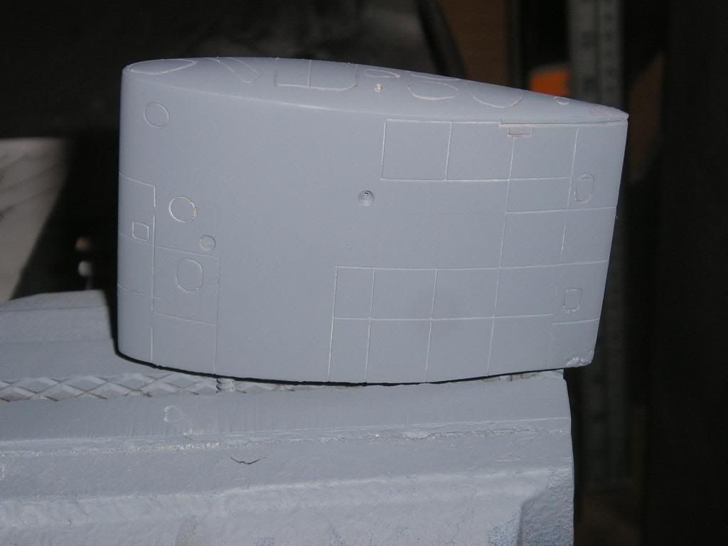
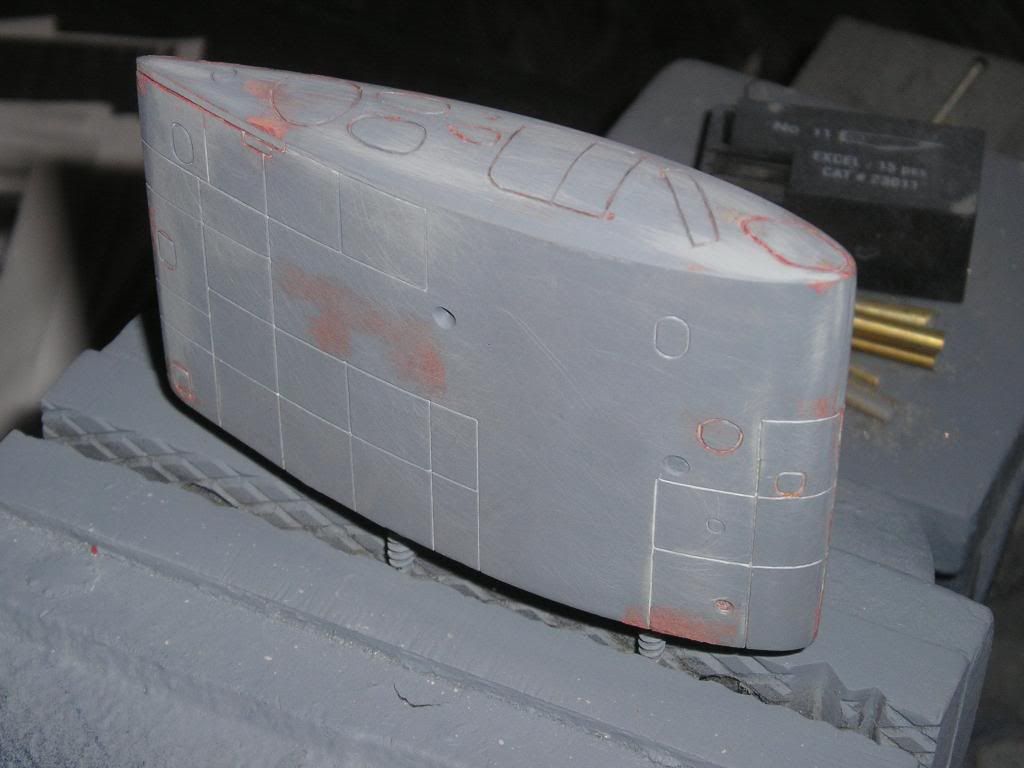
Also, I scribed the panels just deep enough, so that after the modeller puts on a coat of primer and then paint it should knock the lines down to where they will stand out a little less, just like the real boats...scale, and Metal!
Hello,
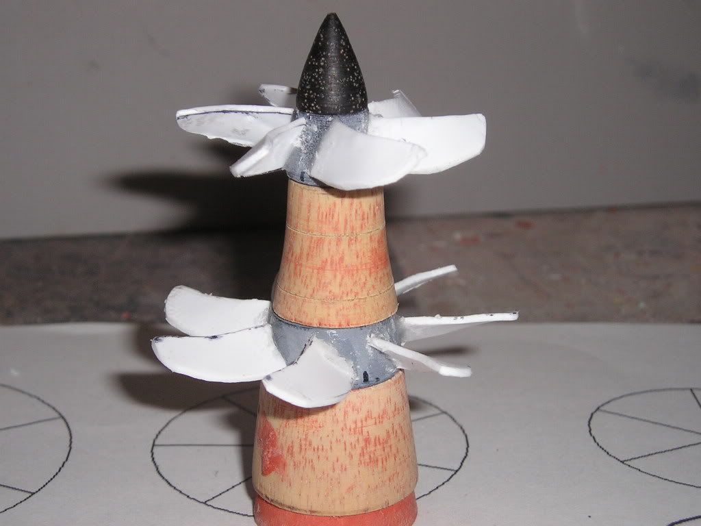
Now that I would pretty much say that the new one piece sail is pretty much done in the way of detailing and the appendages as well, I thought it was about time to tackle the new Jack screws (I’m doing a high pitch Permit one as well. I actually built screws for the Jack way back when, but looking at them now and comparing them to the pictures of the actual screws made me unhappy, they just had to be redone. This time around because of more thorough research I am also doing different things with the blade pitches on the two props. Before I made both props with the exact same pitch as each other, and to my folly, I discovered that this wasn’t the theoretical best way to go. The front larger prop’s pitch has been increased by a quarter diameter and the pitch of the aft prop has been made to double that of the front one.
Some technical data for you all:
Permit screw diameter: 15’
Jack fore screw diameter: 12’
Jack aft screw diameter:10’
The actual design of the twin screw configuration for the Jack wasn’t planned on from the beginning. Portsmouth engineers asked for, and were granted to do the modifications. Perhaps this was why the boat took so long between the laying of the keel and the actual commissioning, or maybe it was due to extra testing needed because of all the extra stuff on board. None the less, the real boats didn’t quite produce the results that were desired by only giving a fraction of a knot in speed increase and around 15% efficiency gains
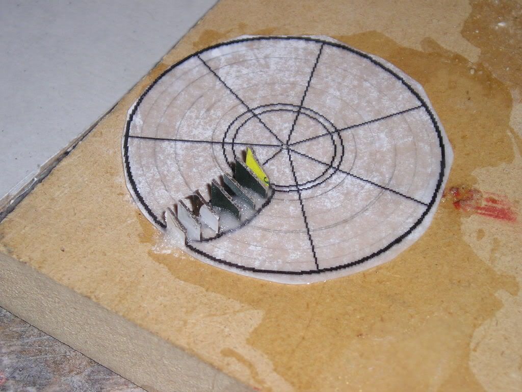
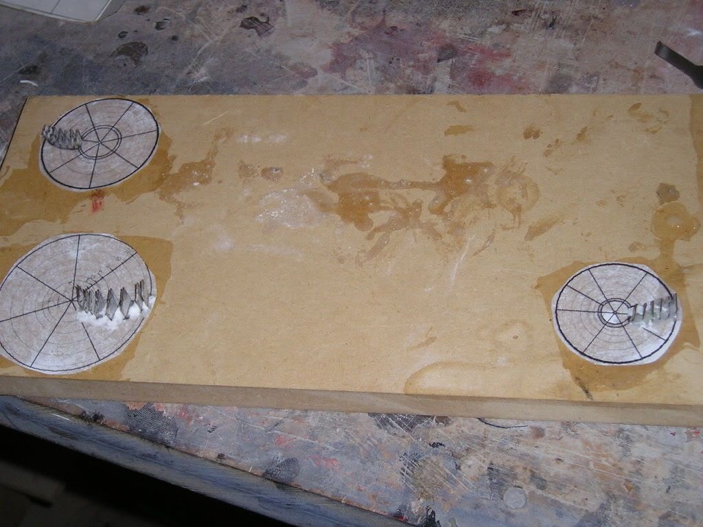
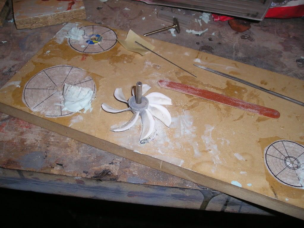
To get started, here are the charts I made to produce the helical twist required to make constant pitch propellers:
The angular sections were glued to circular pie charts printed out on the computer
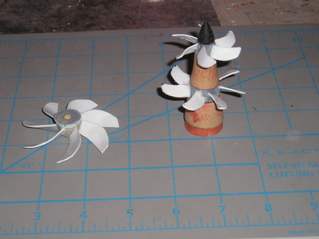
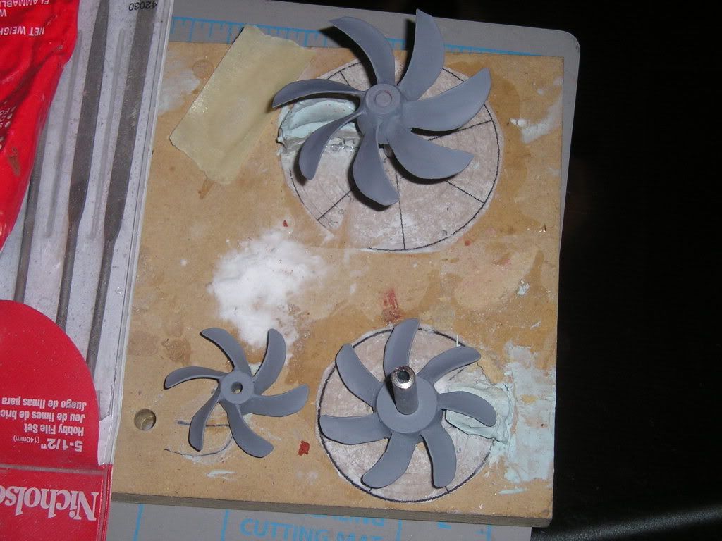
All three prop pitch and position jigs set up on a prop making board
The gaps between the cardboard were then filled with Bondo
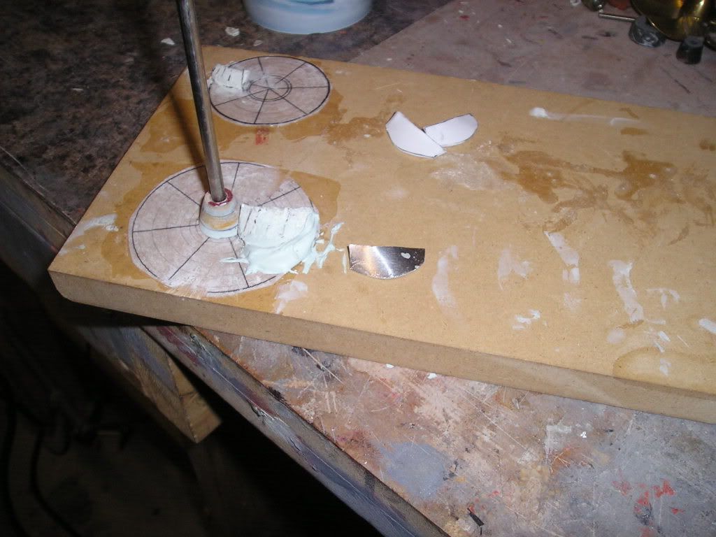
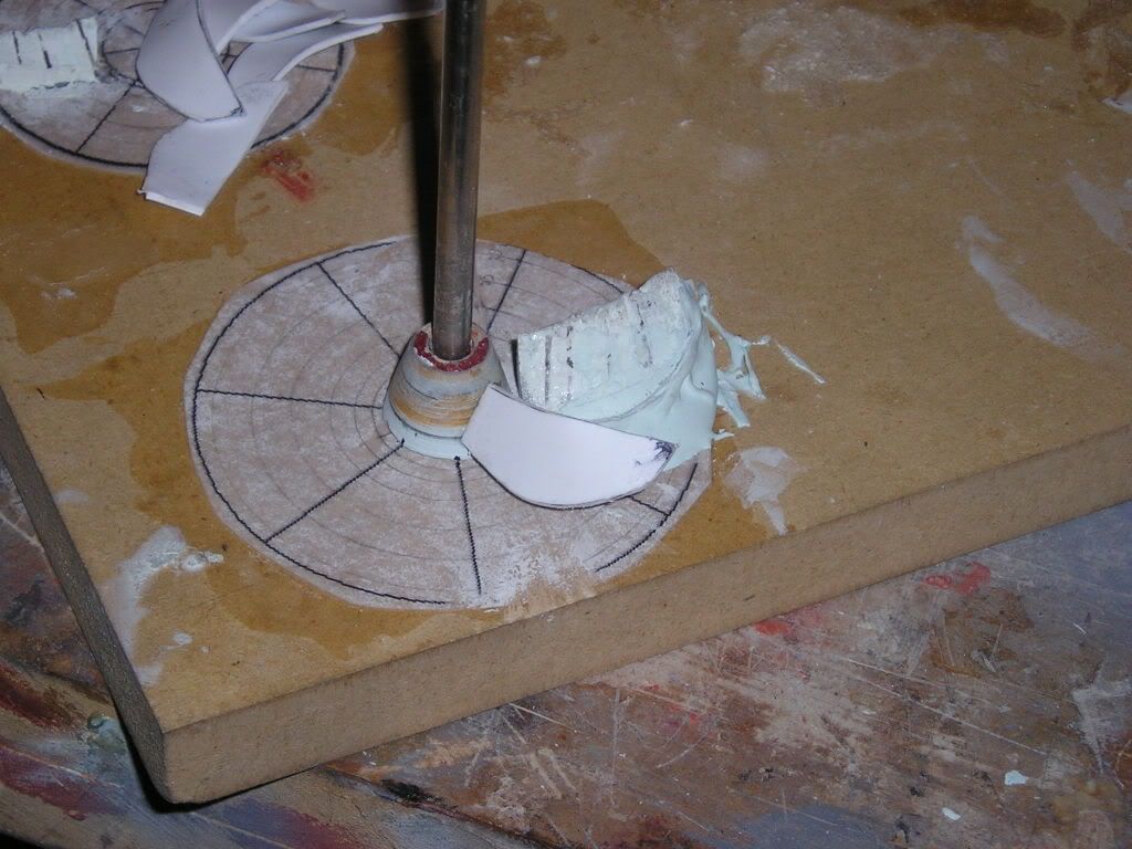
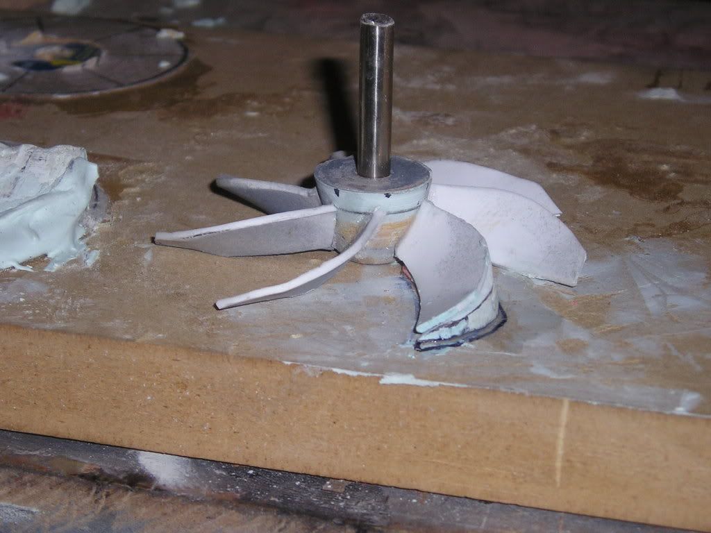
Now this time in my prop making endeavors I am doing something quite different than last time. I am not wasting time or money making moulds from masters of each prop blade. I am making a master blade from aluminum and then forcing the twist shape by simply pressing the blade on my pitch jigs. I then take Styrene sheet cut roughly to size of the master and then clamp it in place. I heat the styrene with my hot air gun and press it to the shape of the master blade. The edges of the styrene are simply then filed to the edge of the aluminum blade producing and exact replica…something that I couldn’t achieve perfectly with a mould, believe it or not!
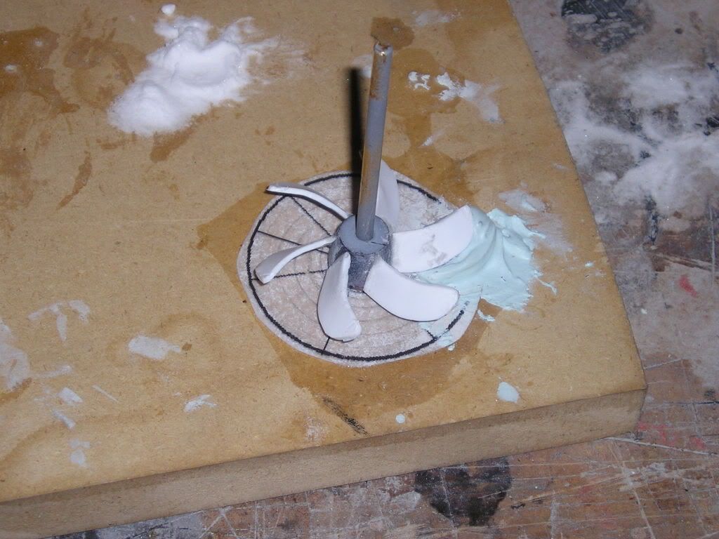
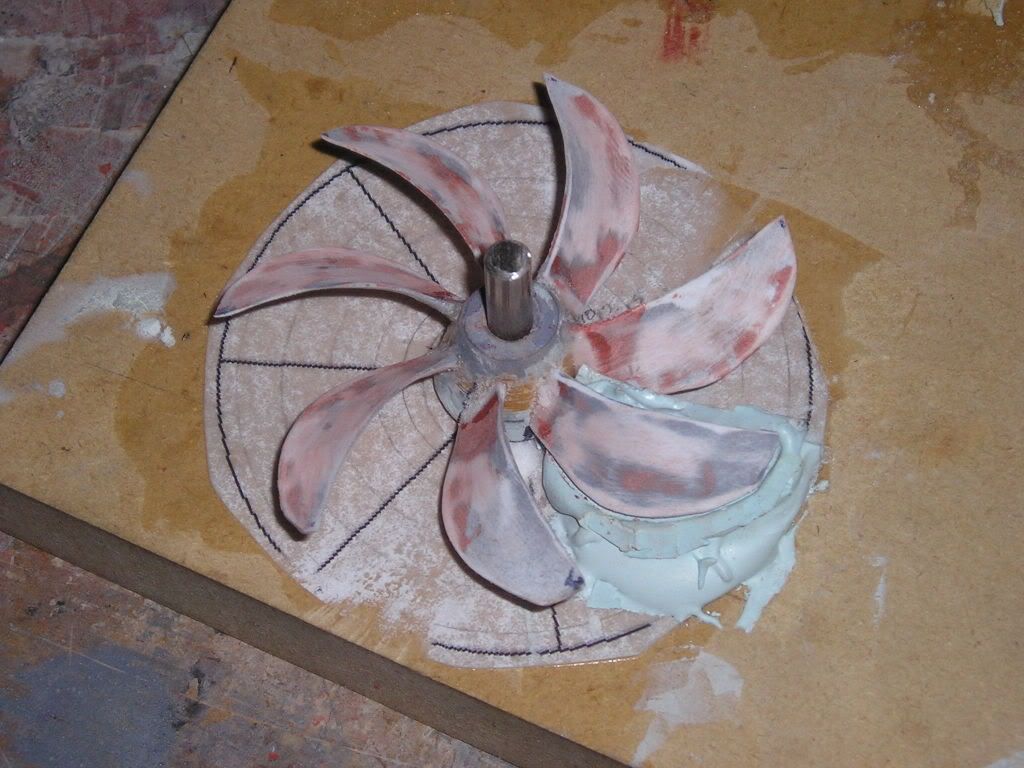
With the hub and shafts in place on the jig each blade is carefully glued onto the hub. Not much glue (CA) is used as I don’t want to make a mess or have it drip down and glue the hub to the jig. Baking soda was also used very sparingly to speed up the process.
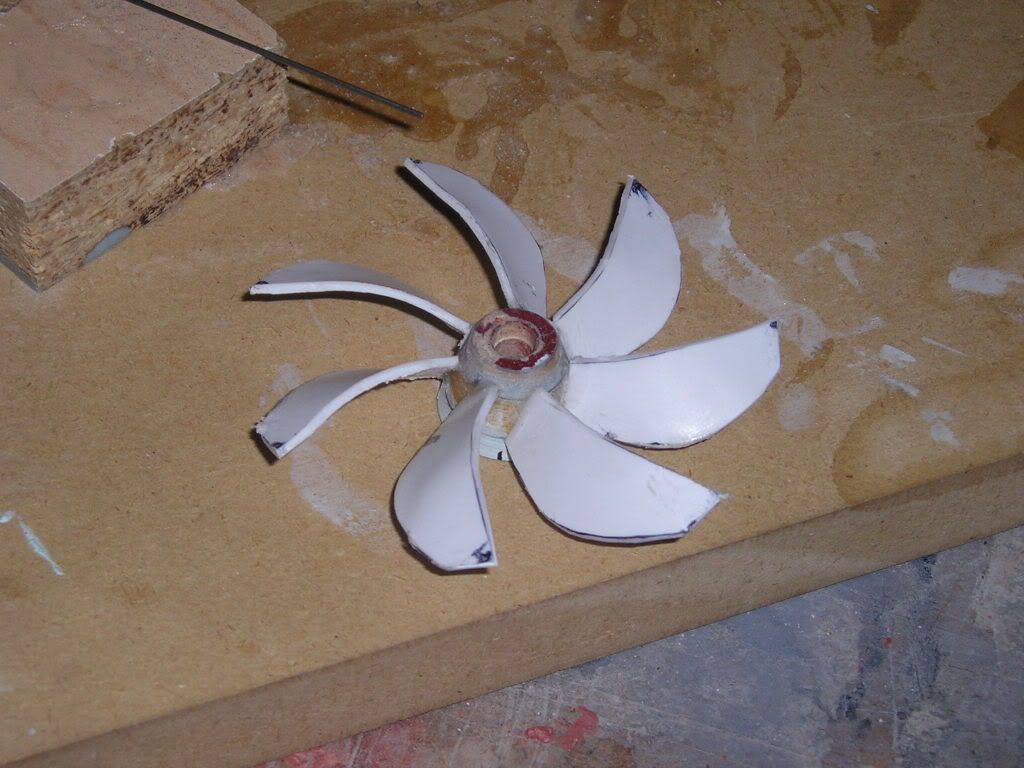
Here is everything assembled]http://i171.photobucket.com/albums/u319/Rapperkiller/P1011395.jpg[/img]
Next, I’ll add blade root fairings and do some blade profiling….Happy new year!
Joel
Good evening,
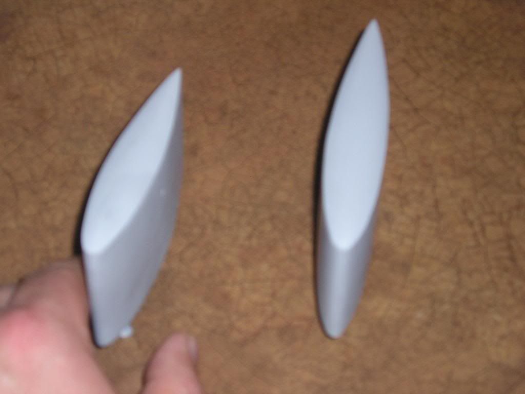
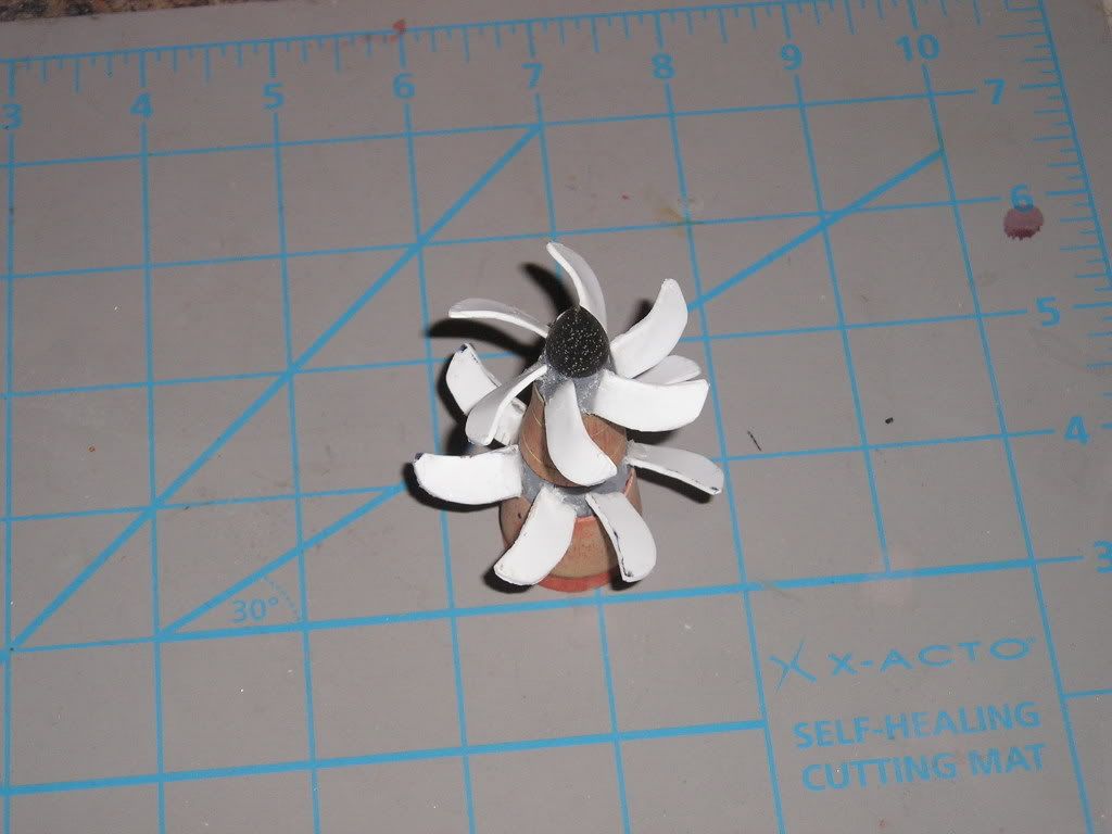
We’re still rollin’ on the screws. Like I said last time I am going to be working on blade profiling. I would define profiling by what you would see when looking directly at the propeller blade from the side of the propeller. What I want you to see is basically a marine version of the Clarke-Y-foil…the basic design of an airplane wing but with the thickest part of the blade brought back from the front tip a little bit. Also, as per some marine prop designs I am adding some cup to the high pressure side of the blade in an attempt to give these props some nice bite when starting from a dead stop.
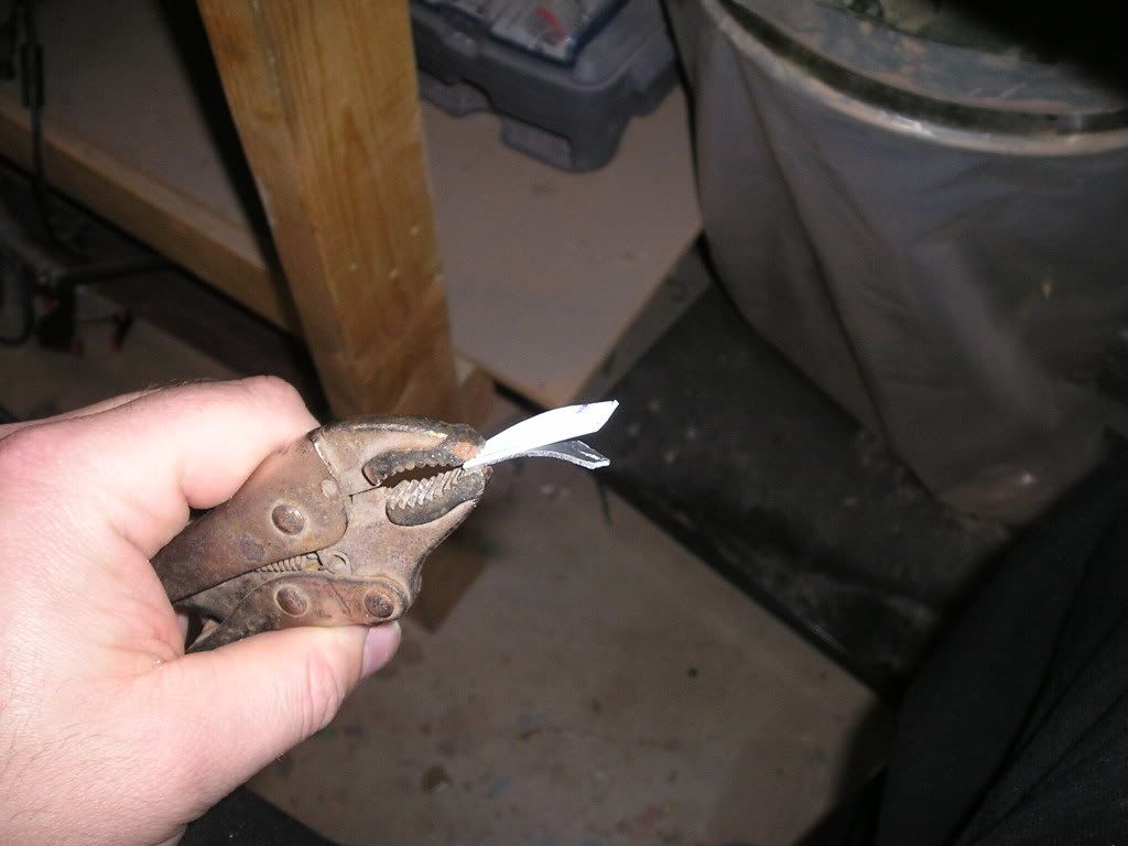
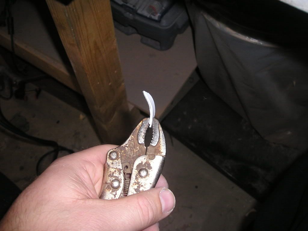
To accomplish all these complex weird shapes an incorporate them all in one blade is damn near impossible to achieve when starting from a flat piece of brass, or whatever., so this where I am really glad that I chose to use styrene as my master material of choice.
First off, I flipped the props upside down and made another blade cradle using Bondo to form to this opposite side.
Lines were marked out where I wanted to have the blade width peak at. The Bondo blade was removed from the work space and I carefully filed my new profile into it. The Bondo-blade was then CA’ed back into place
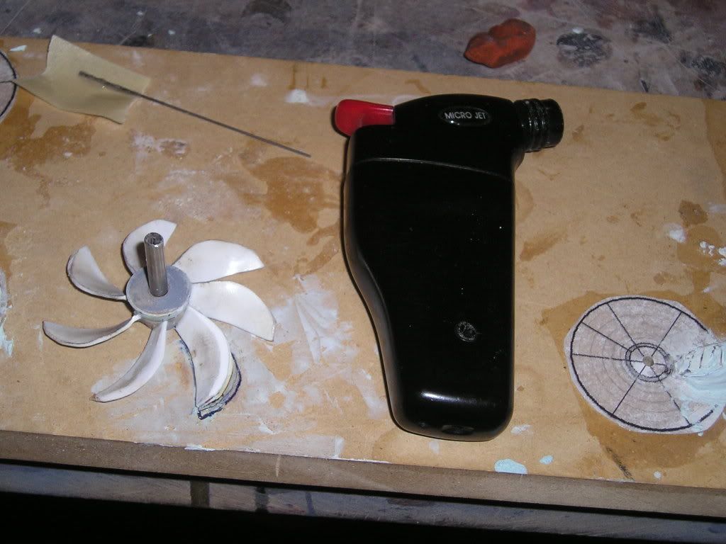
Now, this is where things got a little hairy. With the blade in place on its new curved shaper I gave the blade a quick shot of heat using my little butane torch. I had to really be careful here not to leave the heat on too long for fear of distorting the neighboring blades. Once hot I put pressure on the whole with my finger so that it conformed to the shaper (Yes, it was hot…yes, it did hurt! But after about 5 blades I had no feeling left in my finger so all was good for the rest)
New profiles added to the blades, I then proceeded to “sharpen†the blade tips front and back with files and sanding sticks
Ahoy,
We’re carrying on with more work on the props. Yes, I know, this is going slow, but hey, they aren’t letting me go home from work these days!
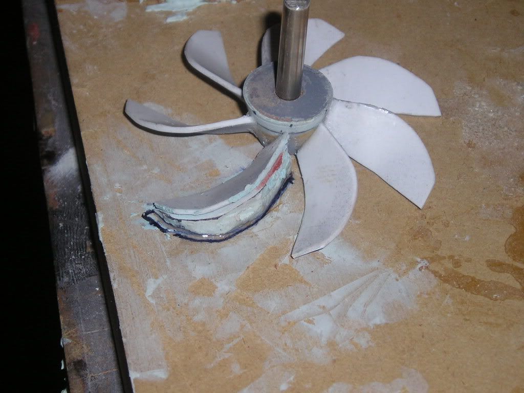
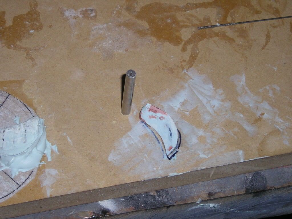
I think the major drawback in using styrene in this application is the weakness of the joints connecting the blades to their respective hubs. But whatever though, I have been making cradles and supports that back up the blades when I work them
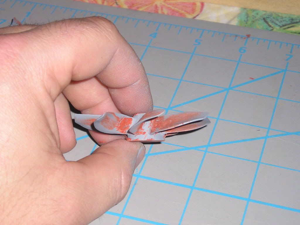
One thing I have done differently on the props compared to past efforts is my technique of applying the fillets at the base of the blades connecting to the hub. The usual process is to glue the blades on and then build up the fillets using automotive filler. This I glued the blades on, but now I add a very small amount of baking soda to the joint, press it in tight with my round file for the shape. I use my #11 Exacto knife to carefully scrape away any excess baking soda.. I have a little pool of thin CA nearby from which I draw a small amount using wire dipped into it, and in this case I use the very rigid music wire. The wire has enough CA on it that when it comes close to the blade root it then wicks into the CA and instantaneously catalyses to the shape I wanted. This also great increased the blade root strength considerably so I put a little more pressure on with out worrying about breaking a blade off, or more importantly from periodic drops to the hard ground or bench. I have no pictures of this process as I only have two hands in which to work with!
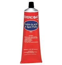
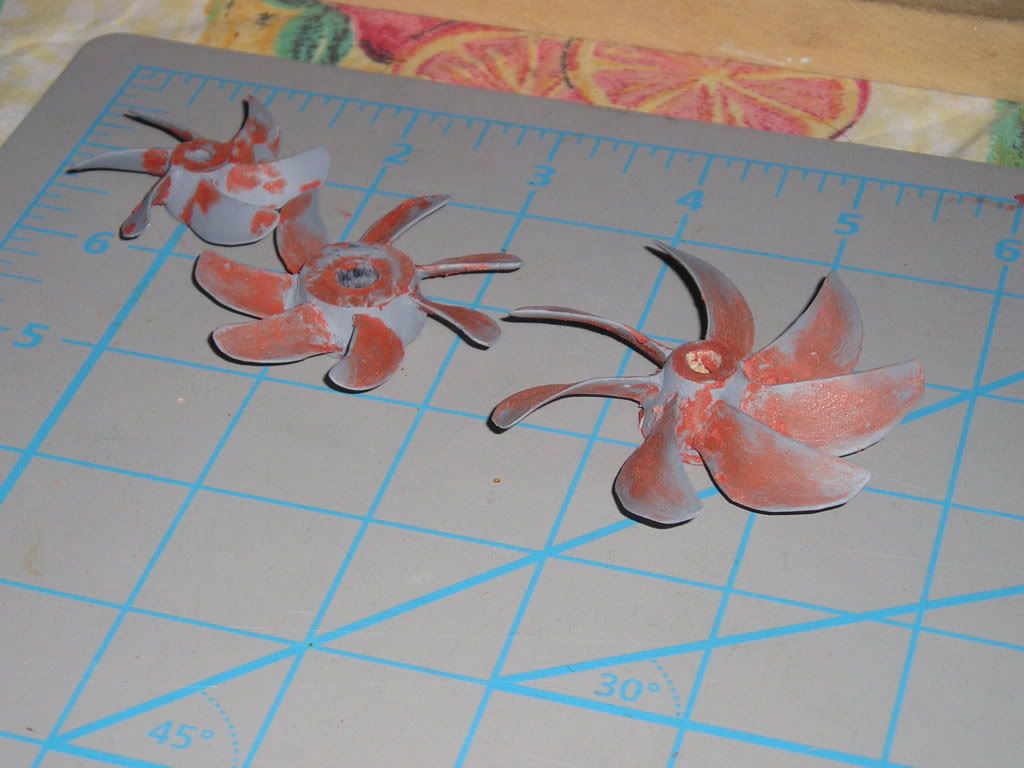
Now to get to what I consider is the most labor-intensive part of building these things; the surface finishing and flaw removal. First thing’s first and that is to give the props a good first coat of grey acrylic lacquer primer and then take a real good look at what you have to work with under some good lighting. All those flaws and imperfections will now “jump out at you†and present you with and idea of what you have to do next. In this case because parts are so small, I will be using red lacquer air-dry spot putty. Right now I use Evercoat brand stuff, but there are many more brands on the market.
I guess the biggest piece of advice on these props is patience. It’s a multi-step process carried out multiple times. I’ll apply the putty sparingly where I think it is needed, then sand it it down when dry. I’ll spray on another coat of primer to see how it looks and then start all over again. I’ll keep doing this over and over and over until I’m happy with the final product – patience. I didn’t have much before starting this big project but it has certainly become more ingrained in me over this time.
Notice the complex helical twist and blade cupping;


Comment