USS Jack

Collapse
X
 
  • Filter
  • Time
  • Show
Clear All
new posts
  • manowar
    Junior Member
    • Jun 2007
    • 173

    USS Jack

    Hello Everyone,
    I would like to formally introduce myself. My name is Joel Stadnick and I absolutely love to build things, and lately over the last year and a half or so, those things have been scratch built submarines. I am also the guy who built the HMK USS Permit reviewed in the last SCR by Paul Crozier

    My background is a mixed one. I live In Calgary, Alberta, Canada and currently, I supervise the instrumentation technician crew at a natural gas compressor-manufacturing firm where we install and commission all the automation and controls for these units. An interesting note here is that we actually test run some of the same engines that the US navy currently use as auxiliary drivers for their newest attack submarine class. Before getting into this racket though, I have worked at various construction jobs with the majority of them involving cabinet and countertop making. I am married and we have two small boys, and as you can guess, they take quite a bit of my free time, but I like to get out in the shop whenever I can. Hobbies include woodworking, electronics, home theater, and of course, model building.

    Getting on to what my purpose is here, I intend to do a build thread highlighting SSN-605 USS Jack done in 1:72 scale based on my Permit class kit that I built over the last year and a half and will utilize many of the same parts used there and modify others, not exactly a true scratch build, as most of the hard work was tackled when doing the Permit from scratch. I will also be offering the Jack as a kit like my 1:72 USS Permit/Thresher sub is. For those interested in reading the full build from the start, it can be found at this link: http://www.subpirates.com/viewtopic.php?t=2540
    I will still update that thread once in awhile, but I think most of what I am going to cover here has already been done over there, plus I would like to make a few new friends over here as well! I definitely invite any questions, comments and constructive criticism that anybody here has to add over the course of the build.

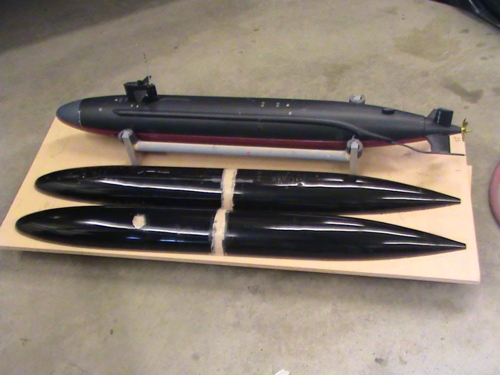
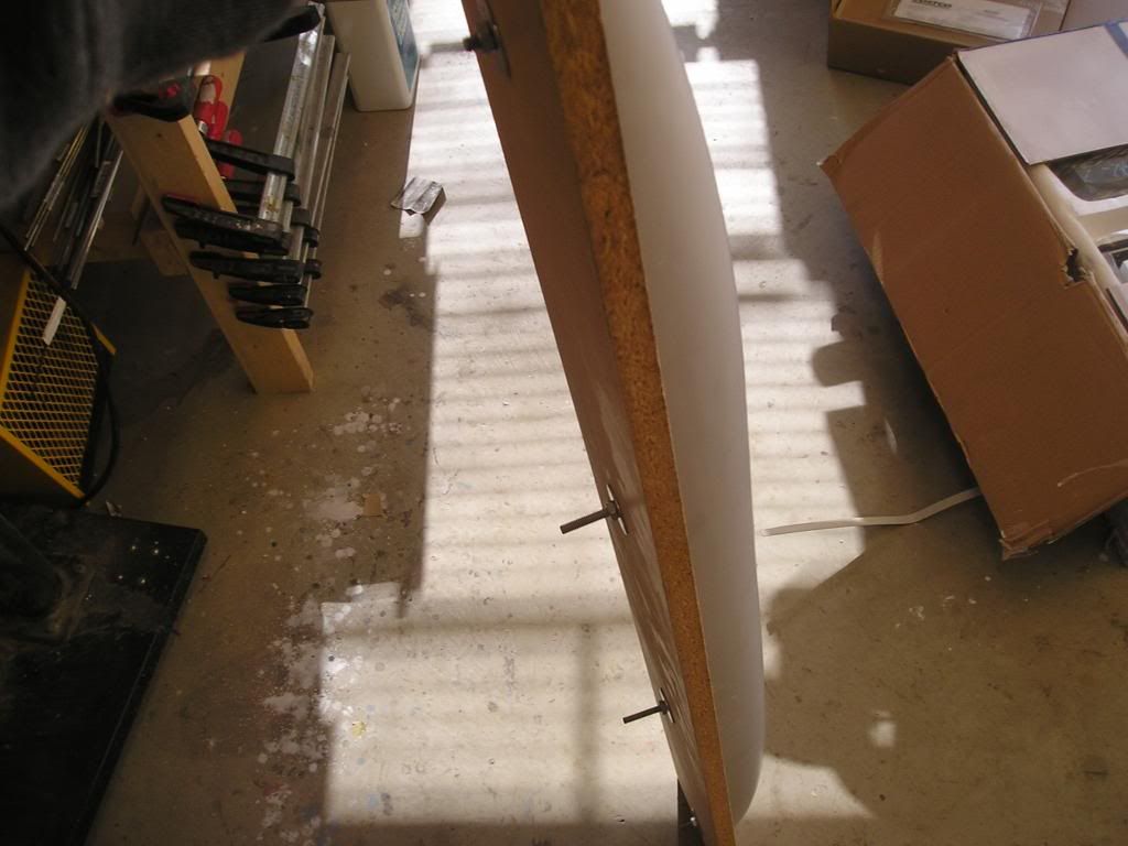
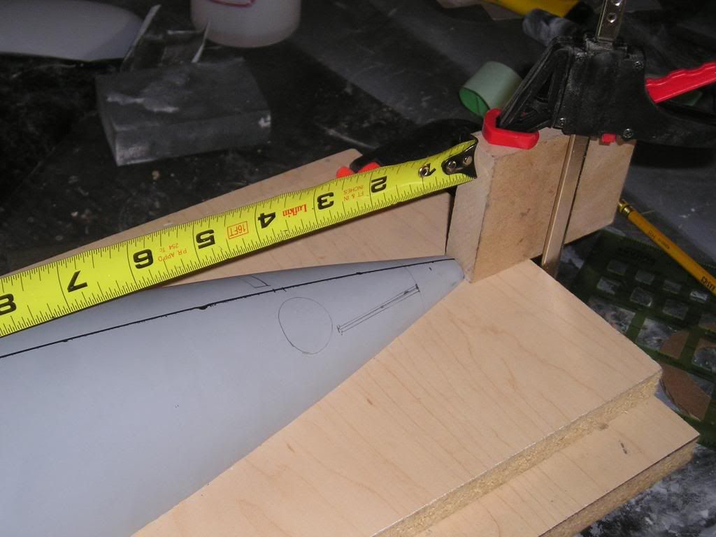
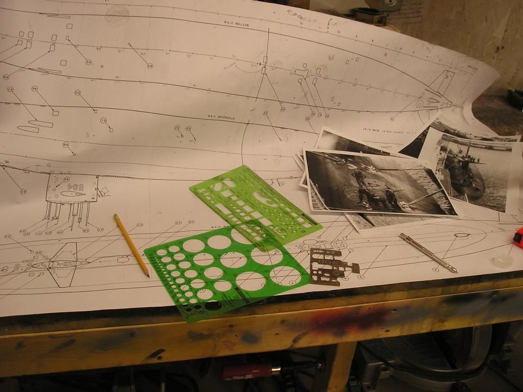
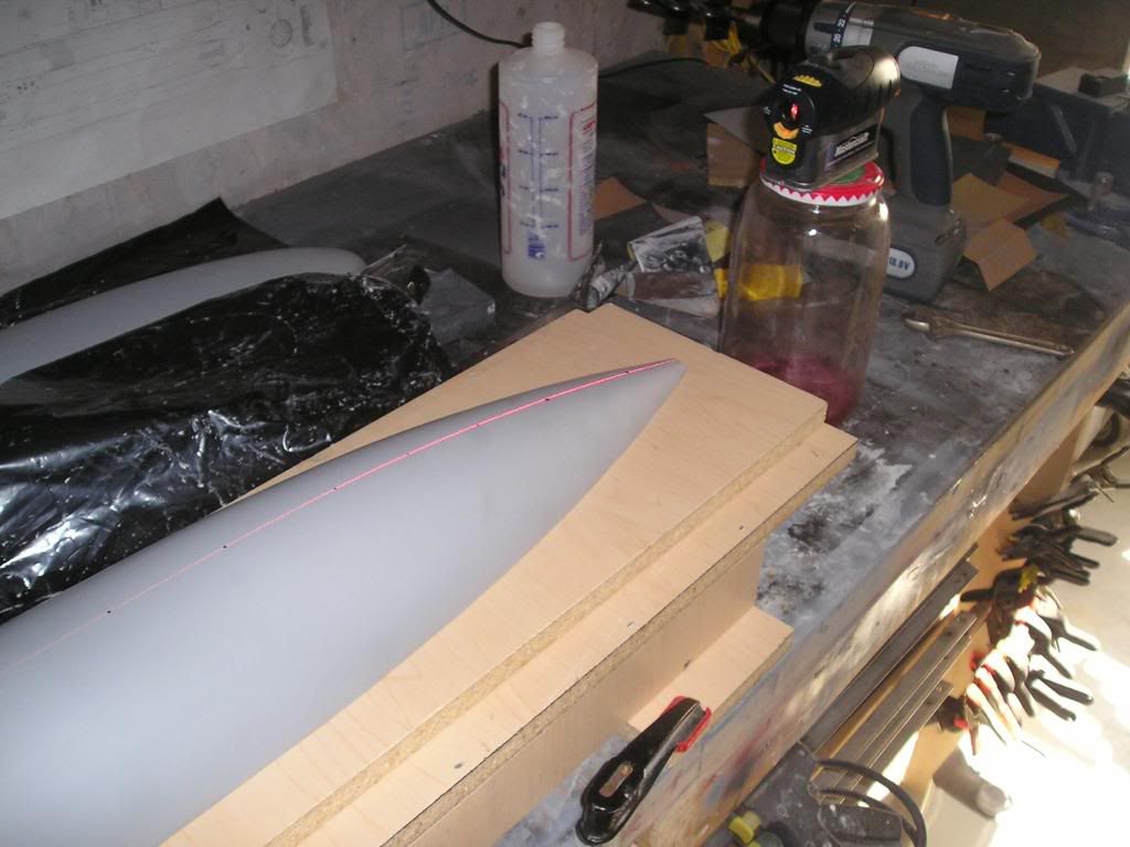
    Here’s a few pics of the Permit boat and the beginnings of the Jack build]http://i171.photobucket.com/albums/u319/Rapperkiller/P1010748.jpg[/img]


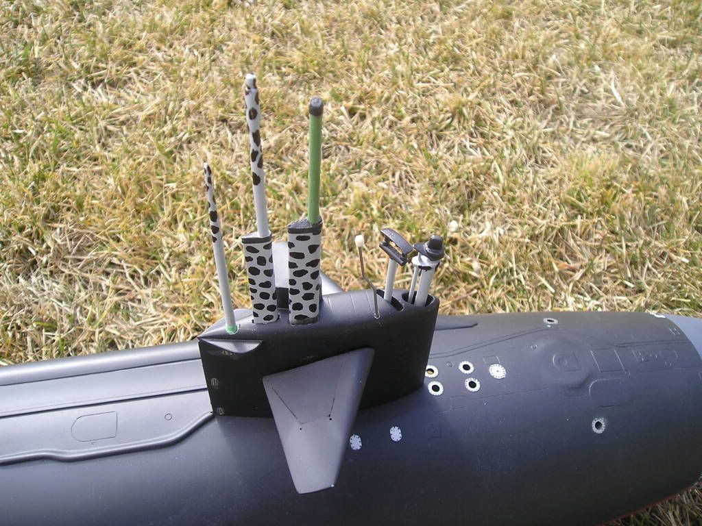
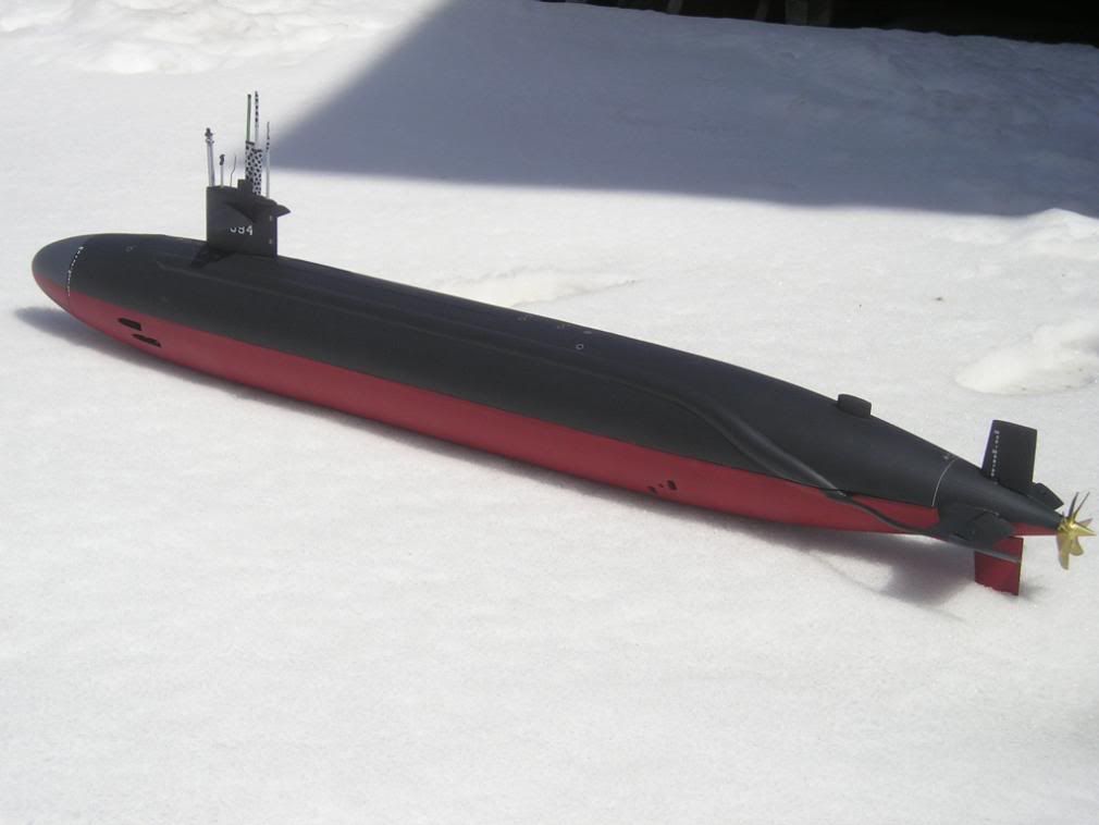
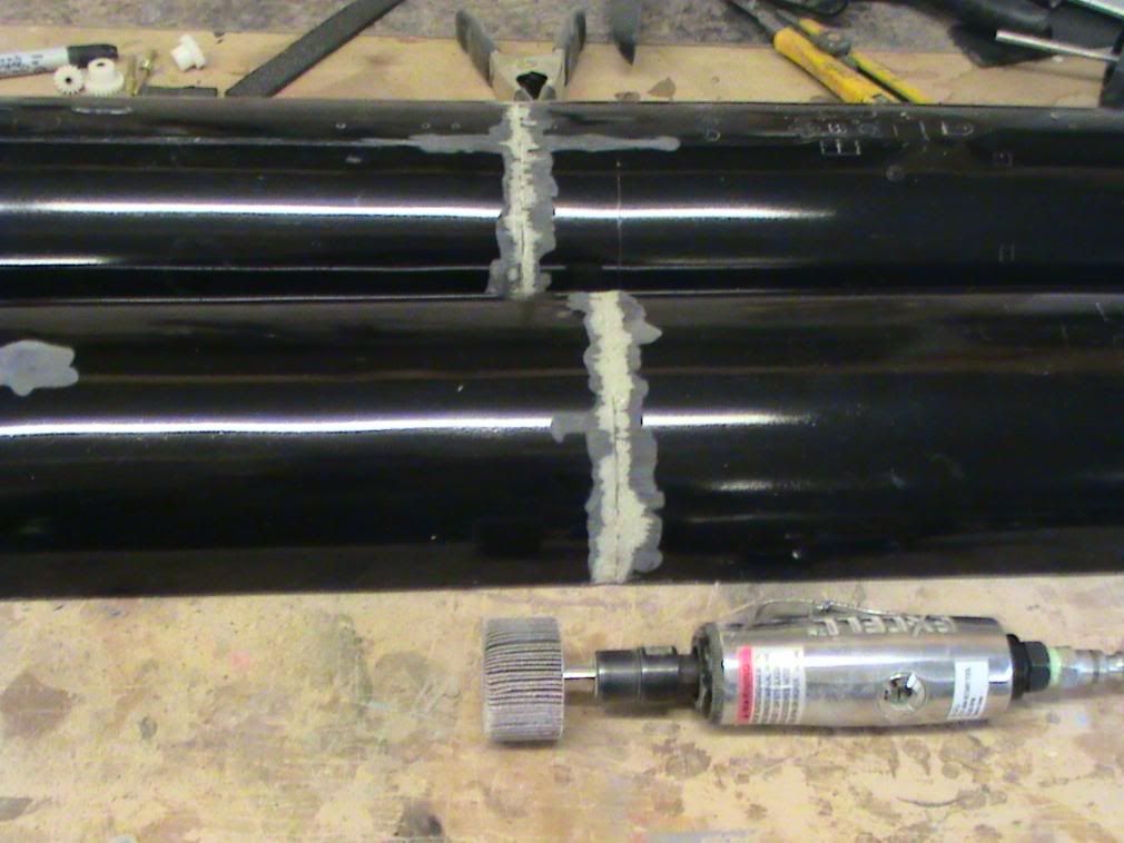
    The Jack is part of the Permit class of attack submarines, which were all built in the late 50’s and early 60’s. It was pretty much a one of a kind boat as it had a very special feature that distinguished it from all other nuclear submarines ever made: It had two propellers that contra rotated on a single shaft. In having this feature the hull was lengthened by 10 extra feet to accommodate the extra machinery that made this system work. The overall length added to a standard Permit was 17’ in total. There are conflicting reports as to whether this configuration actually brought any great performance gains, and the fact that this boat was the only one ever built like it probably proves that there weren’t, but it sure makes for an interesting and challenging model subject!

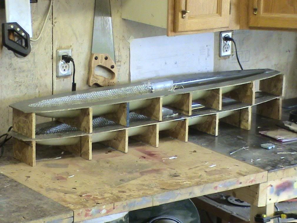
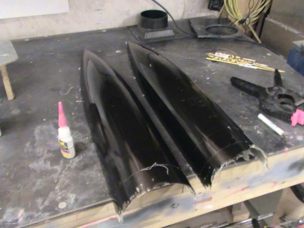
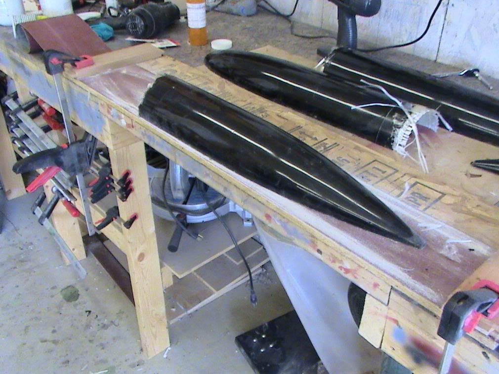
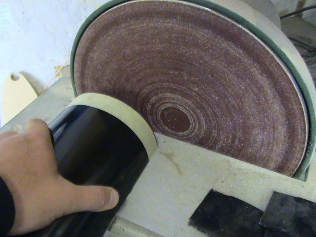
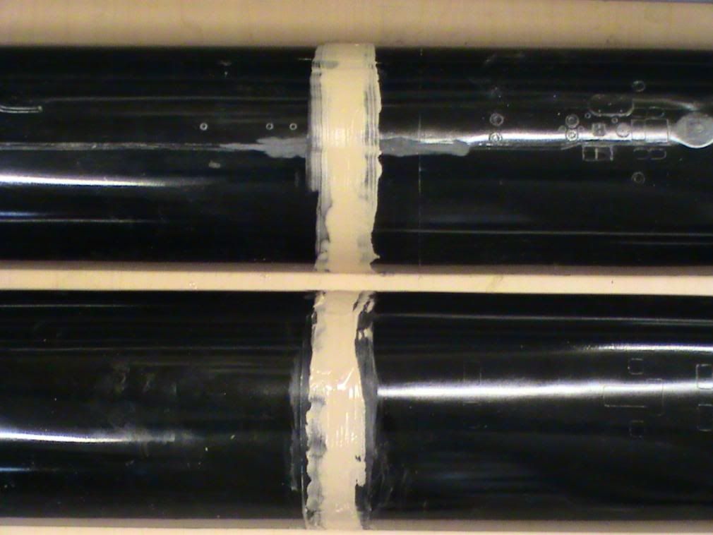
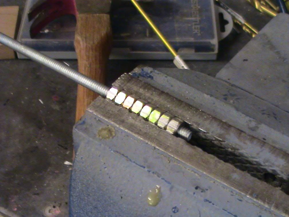
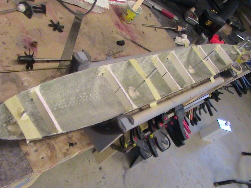
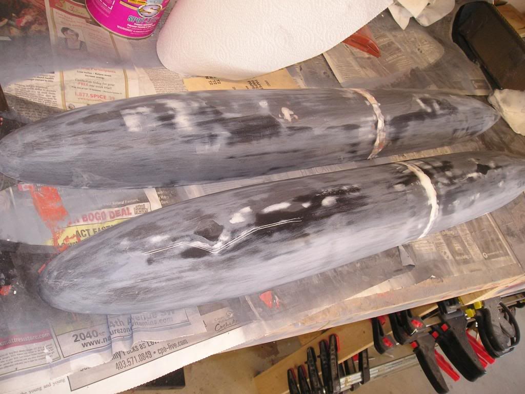
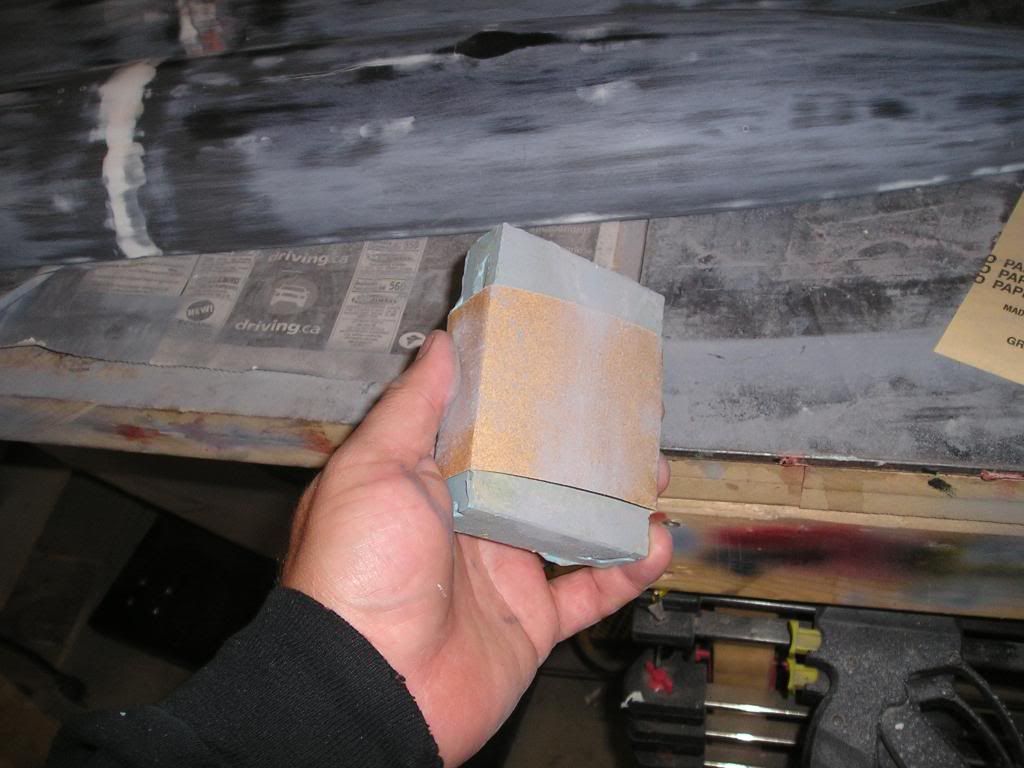
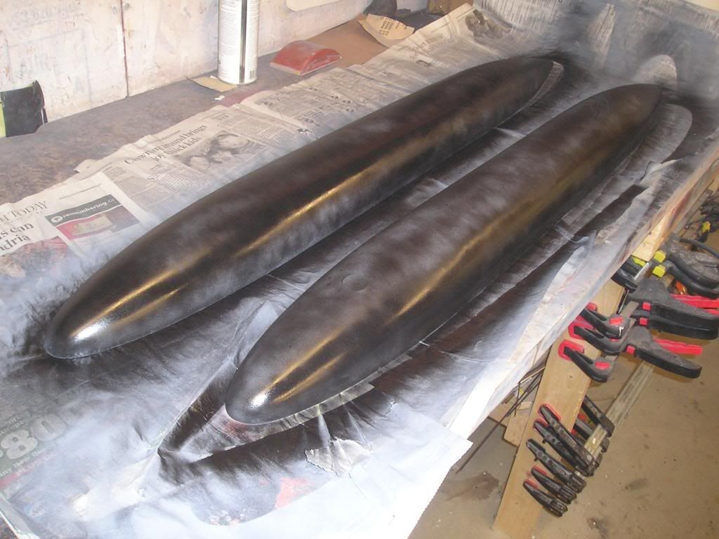
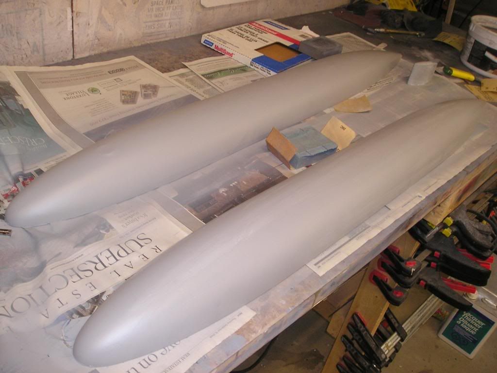
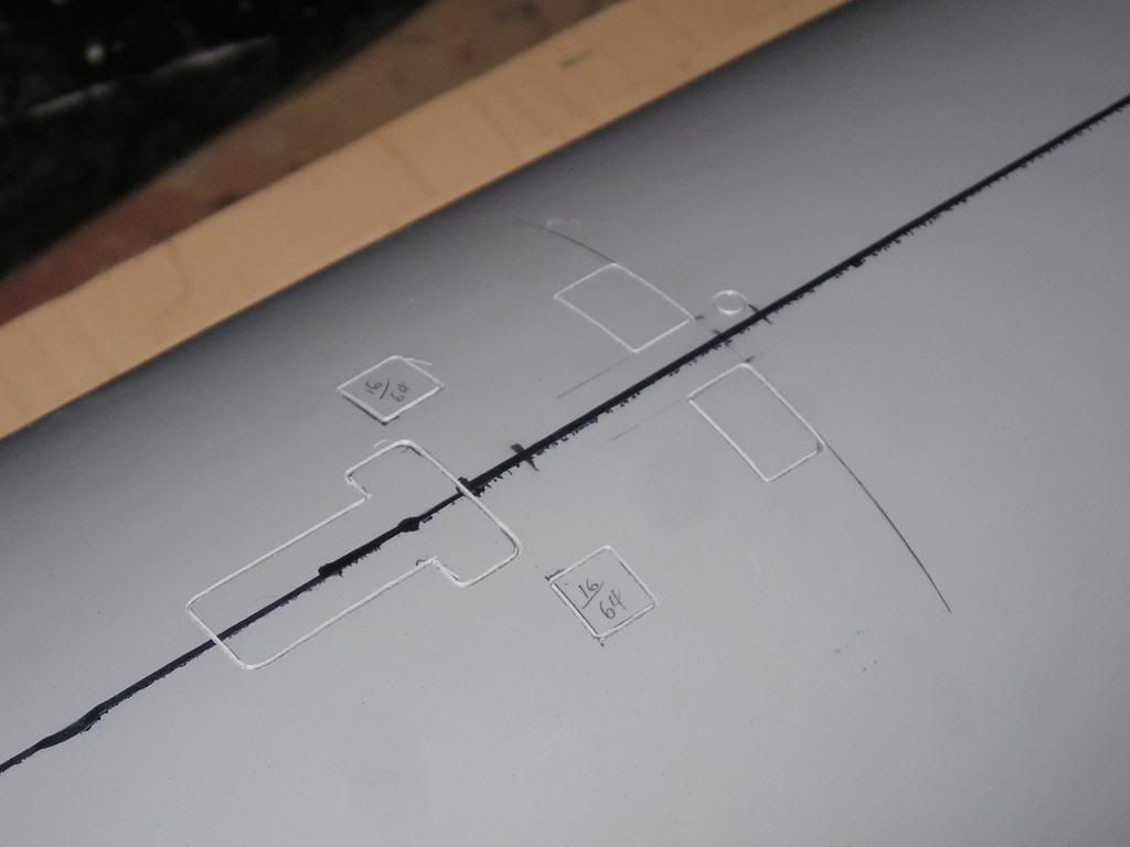
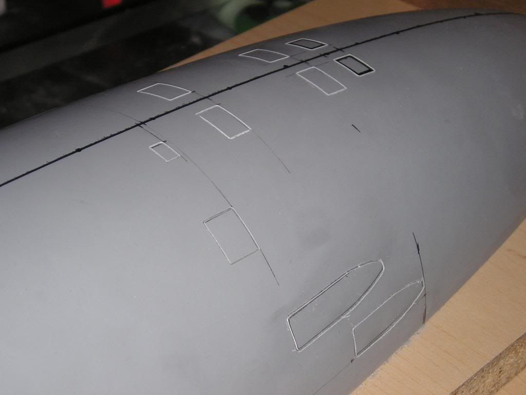
    To Start, we will begin will the hull transformation from Permit mold to Jack plug mold….

    Joel
  • manowar
    Junior Member
    • Jun 2007
    • 173

    #2
    Hull part 1

    Hello,
    To start off with I chose to get going on the hull, as it will be the largest part of this project. I have already made an accurate plug and mold of the base Permit hull, using MDF as the building material and machined to shape on my wood lathe. I will not be making a whole new hull plug for the Jack this time just to add 1 5/8” to the whole thing. Rather, I opted to make two longer pieces of each hull half using my existing Permit mold and then attach them after all the parts were cured.


    Two lines were drawn into both mold halves using a Sharpie marker designating where I wanted my hull seams to be. After lamination the Sharpie marks transferred onto the surface coat telling me exactly were I would have to sand to join the hull halves together. I chose a spot on the hull that wouldn’t interfere with any present detail positioning, a strategically chosen spot if you will. For these parts, I used a very heavy top coat of filled black-pigmented epoxy and then a very heavy woven roving lay-up to around 1/8” final thickness. The goal here is have a very firm part with lots of topcoat in which to scribe into, just like a master tool part should be.

    Before the parts were cured, I fit and adhered plastic stiffeners to the insides.


    Regards,
    Joel

    Comment

    • PaulC
      Administrator
      • Feb 2003
      • 1542

      #3
      Joel,

      Great to see this thread!

      Joel,

      Great to see this thread! Looking forward to your progress.
      Warm regards,

      Paul Crozier
      <><

      Comment

      • manowar
        Junior Member
        • Jun 2007
        • 173

        #4
        Thanks Paul!
        Lots of new stuff,

        Thanks Paul!
        Lots of new stuff, techniques and good info coming up to share with everyone...

        -Joel-

        Comment

        • tmsmalley
          SubCommittee Member
          • Feb 2003
          • 2376

          #5
          Welcome to the gang Joel.

          Welcome to the gang Joel. Super work! Looks like we have a speaker for next year's SubRegatta...

          Comment

          • PaulC
            Administrator
            • Feb 2003
            • 1542

            #6
            That would be a good

            That would be a good choice.
            Warm regards,

            Paul Crozier
            <><

            Comment

            • tmsmalley
              SubCommittee Member
              • Feb 2003
              • 2376

              #7
              Don't laugh Paul - you're

              Don't laugh Paul - you're next!

              Comment

              • manowar
                Junior Member
                • Jun 2007
                • 173

                #8
                Welcome to the gang Joel.

                Welcome to the gang Joel. Super work! Looks like we have a speaker for next year's SubRegatta...
                That is a heck of a long drive for me Tim (1600 miles as the crow flies) but maybe a video presentation might a cool thing for people to watch....
                Either way it would be nice to be part of it

                Joel

                Comment

                • manowar
                  Junior Member
                  • Jun 2007
                  • 173

                  #9
                  Hull Part 2

                  Hello again
                  Continuing on putting the hull together we will start by cutting each quarter part to exact length. It’s impossible to see in the pictures, but my Sharpie lines transferred perfectly to the part reproductions. I masked off with tape on the lines and then cut the majority of excess of with the hacksaw.

                  The next step was to precisely trim to the lines. This was done on the 12” disc sander. Not shown here was the effort put in to making the work table 100% 90 degree perpendicular to the sanding wheel using a speed square. We want a perfect fit when butting up the hull pieces, no gaps!

                  After I was completely happy with how the quarters fit together at the butt joints I ground the insides of the joints to about an inch from the edge using a flapper sander on a pneumatic die grinder. Note that every time I have to do some kind mechanical bond that I grind the bondable surface and then clean with either acetone or laqueur thinner to remove any remaining particulate. Once that was done I aligned the par on a straightedge and tacked them together using thin CA. When the CA dried I flipped the halves over and epoxied in a few layers of 2 and 3 inch fiberglass tape. It turned out to be a very strong bond.

                  With the epoxy cured on the underside (It would have been foolish to do any more work on the hull if it had not) I ground our out a fairly deep groove on the surface side and filled with epoxy mixed with a nice fairable filler. The reasoning here is give me a larger surface area to blend together using the basically the same surface material as the rest of the hull instead (expansion, warp prevention) of trying to fix any abrupt imperfection caused by a butt joint.


                  More hull work to come,
                  Joel

                  Comment

                  • manowar
                    Junior Member
                    • Jun 2007
                    • 173

                    #10
                    Hull Part 3

                    Ok
                    We now have two hull halves instead of 4 hull sections and the epoxy and glass work have given me a nice strong joint on both pieces that cured without any kind of pulling or warping action…like epoxy would do that anyway! The next step was for me to install some multi-purpose anchor points on the insides of the hull halves. These will serve two purposes in life. One to hold the hull halves down to my mold parting board and keep the halves straight and true. Two, to provide an anchor point in which to hold a jacking bolt that will in turn ease the release of the plug from the mold when cured. A guy has to think of this stuff in advance or else he could end up either having an extremely hard time removing the plug from the mold and in turn damaging one and/or the other (please see my Sub Pirates Permit thread to fully experience the adventures I went through experimenting with different molds and trying to remove the plugs).

                    With that being said, here is what I am doing on this hollow shell plug mould. ¼” nuts were threaded onto a rod and squeezed into my vise. The outside surfaces were given the run-through with my hack saw thoroughly roughing up the out sides in preparation for being bonded to the insides of the hull.


                    The nuts were glued into place with a heavy mixture of epoxy filled with fiberglass strands and some colloidal silica to prevent sagging. Threaded rod was cut to size with the burs ground for easy threading. These were greased up with Vaseline and threaded into the bolts and held in place with masking tape. Once cured, I had tough anchor point s for mounting the threaded rods.


                    Next: I’m going to get into getting flaws out and readying the hull surface for detailing. Lots of sanding ahead!

                    Joel

                    Comment

                    • manowar
                      Junior Member
                      • Jun 2007
                      • 173

                      #11
                      hull part 4

                      Hello everyone,
                      We’re back again with getting the hull ready for detailing. Everything you see here was pretty much learned by following Brian Stark’s procedures on his various projects, with trying to get a flawless finish on the plug mould. Really though, for this application there is no one better type of person to follow than a professional body man, of which he is
                      Number one, using very heavy grit sandpaper I’ve sanded down the entire surface of the plug, and this includes all the details. All the scribed details have been filled. Yes, I am redoing all the details as I feel I can do a better job than on the Permit. Block sanding is the order of the day to smoothen out the high spots. To smoke out the low spots, I spray some cheap black paint on in a mist coat and then block sand when dry. If done correctly the low spots should show nicely when done, and then fill them up with an appropriate filler and sand. I kept repeating the process until I was happy.


                      So, with all the things filled that needed filling like details and imperfections in the surface I proceeded to block sand the whole thing down. I am not worried about filling deep scratch marks this time however, I have a secret weapon (of which I’m about to share with all of you) that will eliminate these. Let me first illiterate my goal here, I need a decent surface in which to scribe to and later sand to a polish. The Permit has an MDF substrate (among other different fillers with different hardnesses beneath what I would call a pretty thin layer of Acrylic auto body surface primer. Don’t get me wrong, that primer is the very best for finding flaws and its extreme sandability, but in that case it was the wrong tool for the job. It can be polished but the layer won’t be thick, and when the layer isn’t thick you will be scribing into MDF (or whatever else is underneath that has a different hardness) The scribe lines will also collapse if too close to other scribe lines because the primer just doesn’t have the structural integrity that is needed. This caused massive amounts of spot repairs, and frankly the scribes just weren’t that clean.
                      So here is the answer to all that. After much research (actually I landed on this stuff by fluke) I found some primer that is made exclusively for fiberglass plug mould finishing. I was actually was pursuing the polyester version of this stuff, but the guy at the store convinced me that this vinyl ester stuff was better. It can be sprayed on to almost 1/8” thick in one spraying

                      Now, even though this is super hard, self leveling, and nice to scribe into, this stuff is very thick and has to be thinned quite a bit with styrene to be able to spray out of my conventional HVLP gun. It also has a 10 minute pot life after being catalyzed with MEKP. Oh Ya, did I mention that this stuff stinks?? The smell somehow got into my house from my attached garage, even with all the doors shut and all windows closed on the house. Definitely use proper breathing filtration of even supplied air and a mask when using this, no question asked!


                      This also isn’t as easy to sand. I started my polishing procedure using 220 grit wet sand, then going to 340 and then stopping for now at 400. The things to remember are to change your water after going up to the next grit paper and squirt in a little dish soap in each batch. This prevents clogging in the sandpaper.
                      Details next
                      Joel

                      Comment

                      • manowar
                        Junior Member
                        • Jun 2007
                        • 173

                        #12
                        Hull part 5

                        Hello again,

                        It’s time to start working on detailing the Jack’s master hull plug tool. Before this can be done I had to figure out a way to keep the hull halves steady and firm so that I have both hands free to scribe and hold templates down without worrying about things moving around when I have to apply extra pressure here and there. Last time I had a heavy MDF master that held itself down and didn’t move around very much, but this time I only have hollow, much lighter GRP laminate parts.

                        Those bolt anchors that I epoxied into place will now be placed into service. The threaded rod was threaded into place and then I took a flat board and drilled out holes for the rods to go through. Nuts and fender washers were tightened down on the other side to hold the hull half in place. Note: these nuts were only tightened enough to hold the part firmly to the board, I don’t want to go overboard and tear the anchors out from the inside. They are only nuts epoxied in place to plastic, not welded to steel this time. Looking back at doing this technique, I couldn’t be happier with how it worked out. The edges of the hull lay exactly flush to the boad and keep the hull perfectly straight.


                        Now, to hold this “parting board” down and to keep it perfectly straight I pulled out the old parting board-box that I used for my complete Permit Hull. I clamped my new board to the old one with the bolts from the new one clearing the previous’ hull cutout. I then clamped the whole assembly to my bench to keep it secure for some heavy-duty scribe action.

                        The final step here was to give myself a way to transfer measurements to the hull from the prints in an accurate manner. In the picture I clamped blocks on both ends of the hull so I had a flat surface for my measuring tools to stop against. I later mounted longer straight blocks along a perpendicular line in relation to the hull’s long straight midsection part. This gave me the ability to transfer measurement around the entire radius instead of just the top.


                        Measuring and applying detail next,

                        Joel

                        Comment

                        • manowar
                          Junior Member
                          • Jun 2007
                          • 173

                          #13
                          Hull Part 6

                          Hello Y’all
                          It’s time now to get down and dirty and start scribing the Jack. There are some things to bring up about the detailing of this boat before we begin though. As everyone knows I based my Permit boat on the Deep Sea Designs prints by Greg Sharpe based out of Victoria Canada. The prints are very accurate for the Permit and they were used as a guideline for the Jack using most of the included details. I am, however, obsessed with the Jack, to the point were at lunch times at work I’ll bring up all the pictures I have of the boat and meticulously look through them over and over. I can recall that on more than one occasion I’ve caught myself looking at a single picture for the whole half hour! Now, through all this I have found some differences between the boats top-side detailing. There is an extra set of cleats on the bow, the safety track in the stern has a different shape by the hatch, I have added a few panels and compartment doors that I have found, lot of little things that make this boat unique from the Permit. Also, this time around I will be adding a designed water line and a sonar dome marking. I wished I had added these to my last model and I made my dream come true on this one. Now, I know you Permit aficionados are saying “Joel, they didn’t add a discernable fiberglass dome until around 1979” and I am going to say “well whether it’s steel or fiberglass, I still see a separation line for that part, although the steel isn’t as visible as the fiberglass it’s still there.

                          One more thing that might be interesting to a few people out there. I see a lot of similarities in the Jack hull, which is a long hull, and the three other long hull Permit class boats...and that is besides the hull’s lengths. Hmm, that might come in as convenient later on…hmmm… wonder why…hmmmm…


                          Alright, with the hull secured down to my board the most important thing I have to do now is find the center line over the length of the boat. Several different size circles were drawn out on cardboard with the half way and right angle lines drawn on. These circles are cut out and the cardboard is fit over the hull and the lines are marked periodically down the hull so I can run my laser down, tape off and draw the rest of the line. I use cardboard a lot for this kind of stuff, a really cheap easy to access material that has a bit of structural firmness.


                          Details are measured and marked out again


                          Aux motor hatch and floods with scratches. I’ll show how I fix the flaws coming up.


                          Notice the torpedo doors look a little rough. This was due in part to excess scribed material left in the grooves and little clean up needed with the machinist’s scribe tool. I’ll say this though; this new surface coat gives me a fighting chance now to put a decent scribe in the first time.

                          Lot’s more to come,
                          Joel

                          Comment

                          • bill rogers
                            Junior Member
                            • Sep 2003
                            • 90

                            #14
                            USS JACK

                            Joel,

                            Great work. I've learned a lot watching both your PERMIT and JACK threads. Can't wait to see more.

                            Bill Rogers
                            1255

                            Comment

                            • polaris
                              Junior Member
                              • Feb 2008
                              • 107

                              #15
                              Yes, I agree with Bill,

                              Yes, I agree with Bill, I cant wait to see more, like a 1/72 Seawolf perhapps.

                              Comment

                              Working...
                              X