February 18th =================================================
Sun is out thought it's 40F.
It is windy but not so much.
I can count the blades on the roof vent spinning.
Okay, in to the shop and turn on the heater.
I plan to paint but while it warms up, I will finish the deck holes by hand turning the drill bit to clean up the CA I put on the bare wood.
This takes a few minutes.
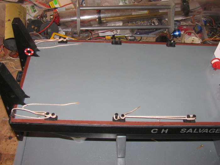
Look at the life rings to see if I need to do more.
Nope, they are going on the barge as is.
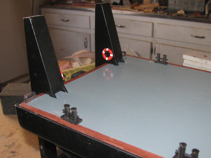
First 2 rings are going on the pusher bars.
The pusher bars are off the barge deck so I can lay the pusher bars on their sides and set the rings down flat.
Moved them around until I think they look right.
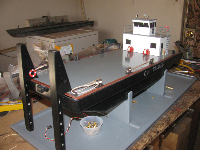
Get my Exacto knife to get silicone glue out of the tube and put the glue on the life rings in four spots.
Using a 1/4" block to get the height right, I carefully set the ring on the side of the pusher bar.
I was originally going to put them on the outside of the pusher bars but when I looked at it, there was not room.
I mean if the barge was working a man could not work on the outside of the pusher bar with the ring in the way.
So, I looked at them on the inside and that is where they are now.
Next to the deck house.
Again I was going to place the rings on the sides of the deck house railing.
And again it does not look right.
Tried a couple other places and the one that looks the most correct is on the back hand railing.
A little silicone glue and there they are.
After the railing ones cure, I think I will use some thread and tie them to the railing to make them more secure.
From the stern.
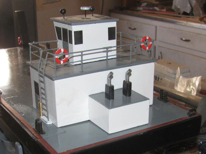
From the bow.
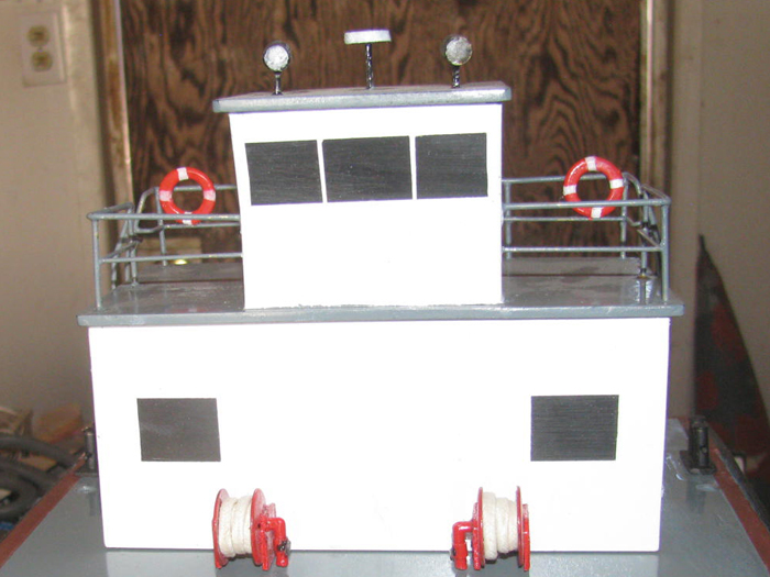
I might try coiling some thread to look like rope but so far I have not had any luck with my big fingers.
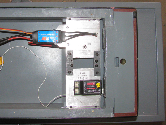
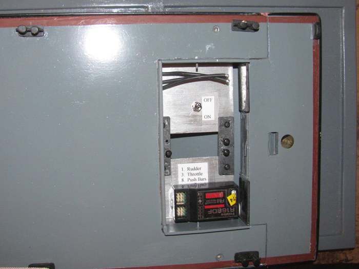
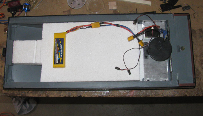
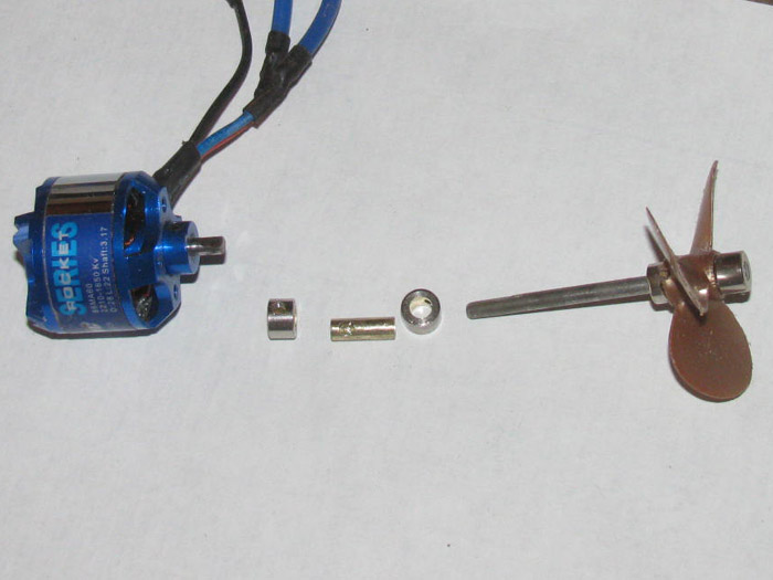
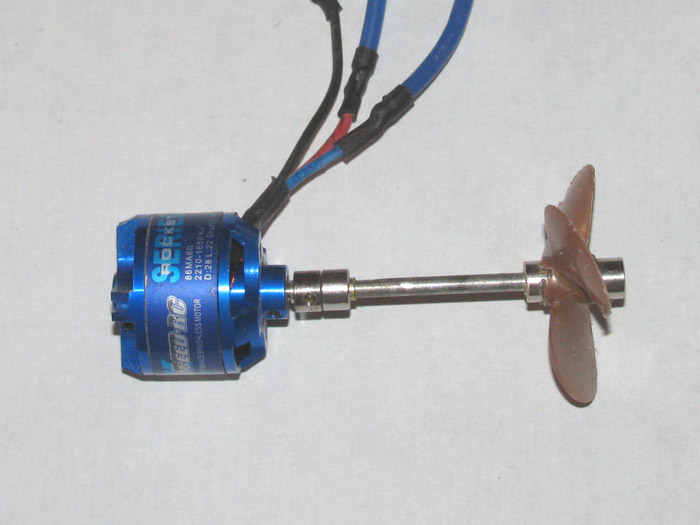
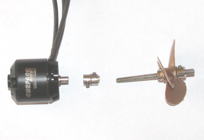
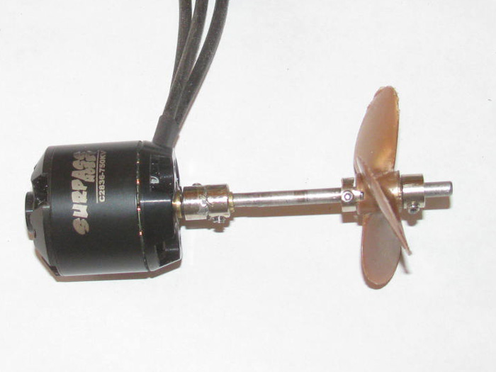
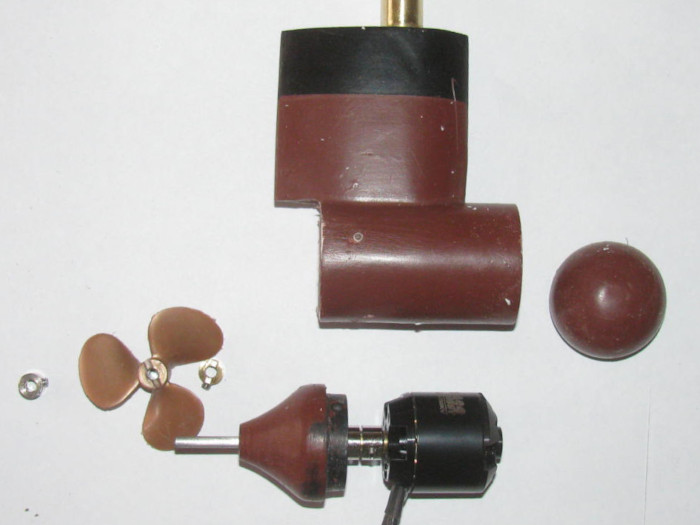
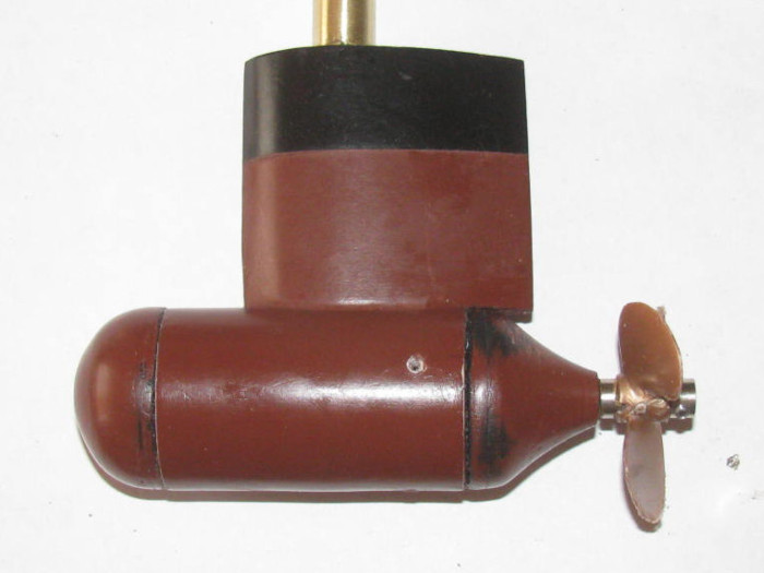
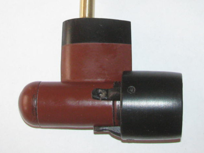
I have reached the point that I am waiting for the new main motor and rudder servo.
Other than making little detail parts to put on the deck, I think I am done.
A tool box at the front of the deck house might look good.
Couple 3 oil drums, maybe.
Well, until water trials and then I can paint the waterline.
I noticed there is black paint splatter on the deck house in places.
They did not wipe off.
To fix it, I would have to repaint the deck house completely.
I do not think that is going to happen.
Sun is out thought it's 40F.
It is windy but not so much.
I can count the blades on the roof vent spinning.
Okay, in to the shop and turn on the heater.
I plan to paint but while it warms up, I will finish the deck holes by hand turning the drill bit to clean up the CA I put on the bare wood.
This takes a few minutes.
Look at the life rings to see if I need to do more.
Nope, they are going on the barge as is.
First 2 rings are going on the pusher bars.
The pusher bars are off the barge deck so I can lay the pusher bars on their sides and set the rings down flat.
Moved them around until I think they look right.
Get my Exacto knife to get silicone glue out of the tube and put the glue on the life rings in four spots.
Using a 1/4" block to get the height right, I carefully set the ring on the side of the pusher bar.
I was originally going to put them on the outside of the pusher bars but when I looked at it, there was not room.
I mean if the barge was working a man could not work on the outside of the pusher bar with the ring in the way.
So, I looked at them on the inside and that is where they are now.
Next to the deck house.
Again I was going to place the rings on the sides of the deck house railing.
And again it does not look right.
Tried a couple other places and the one that looks the most correct is on the back hand railing.
A little silicone glue and there they are.
After the railing ones cure, I think I will use some thread and tie them to the railing to make them more secure.
From the stern.
From the bow.
I might try coiling some thread to look like rope but so far I have not had any luck with my big fingers.
I have reached the point that I am waiting for the new main motor and rudder servo.
Other than making little detail parts to put on the deck, I think I am done.
A tool box at the front of the deck house might look good.
Couple 3 oil drums, maybe.
Well, until water trials and then I can paint the waterline.
I noticed there is black paint splatter on the deck house in places.
They did not wipe off.
To fix it, I would have to repaint the deck house completely.
I do not think that is going to happen.

Comment