I usually post my builds on Sub Pirates forum but it seems the forum was lost while trying to move it to a new host server.
I can not post all my builds again but I will try to post my current build.
I will copy from my build logs on my personal web site.
I am not sure whether I post post post for post or put more than 1 post in each post here.
Won't know until I start.
So here goes.
====It started on Nov 14th, 2020==============
Last time out with my Akula II submarine, (Nov 14th) I ran it so long that the BEC cut main power to the propeller motor.
There was no wind that early in the morning.
I had no where to be that was important so I decided to just sit it out until the boat came to shore.
The real question was which way would the wind blow when it came.
The boat was about 150' out from shore but if the wind blew off shore, the boat would go across the lake and it was about 3/4 mile around to the other side.
I got lucky because there is an aerator out about 175' out from shore and this causes a very slight current moving sort of towards shore at about 90 degrees from where I was using the park bench.
Using trees on the far side of the lake, I could see the sub moving about 10' every 15 minutes and in the right directions.
Then I noticed the leaves on the tree above me where starting to move slightly.
Good news, the wind was in the correct direction so far.
From the time I lost main power until I could reach my sub with the antenna I removed from the Tx.
It took about 1 hour 45 minutes.
Got to sit in the park and enjoy the morning. (A bit of stress)
Everything turned out just fine.
This would not have been a problem if I had taken a second boat with me.
I did not.
I also was running alone because this was not a group day to run.
So there where no other boats of any kind to help push the sub back to shore.
While sitting there watching my sub slowly drift towards shore, I thought I needed to bring a second boat every time I go out.
Also thought I might build a rescue boat for just this sort of thing.
Have it with me for me and any one else who might need rescuing.
There have been others that have gotten stuck off shore and needed a push.
I posted this adventure on Sub Committee and got a response from Greg with attached photos of his rescue barge.
Very simple design and much like I was thinking sitting in the park.
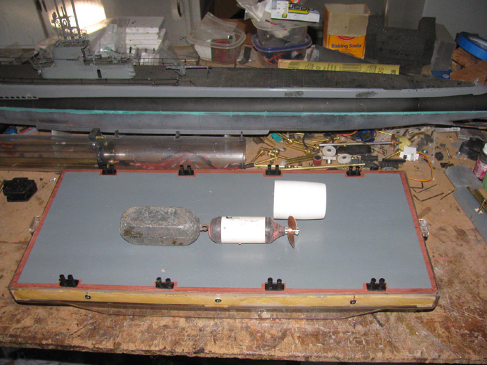
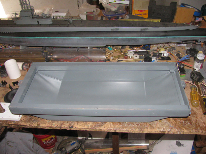
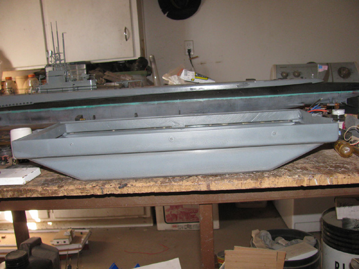
A cement mixing box, square in shape and rounded up are both ends.
Greg made me an offer of a hull like his that I could not refuse.
It arrived with in a few days. (Greg, Thank You)
So here is where the build will start.
====================================
The building of a Rescue Barge.
November 14th =================================================
I looked through my parts box and I think I have everything but a propeller the size I want to use.
I have spare sub propellers but they are either to big or too small in diameter.
I have ordered parts.
Couple of propellers and a couple of dog bone universals. (spares)
I have thought about it.
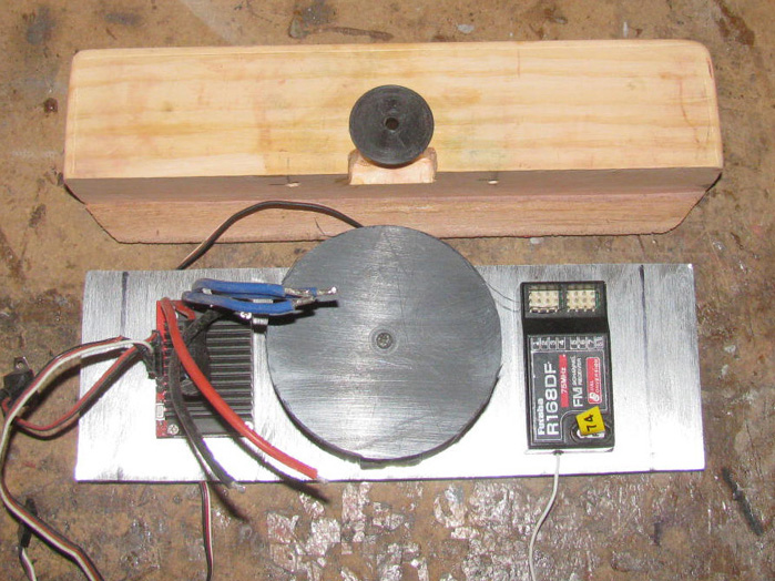
A propeller with 2 rudders or a Pod hanging below the hull with the motor in it.
The steering linkage is simple.
I can get about 100 degrees from a 60 degree servo using 2 wheels with notches and cable.
I am going to start building a propeller pod.
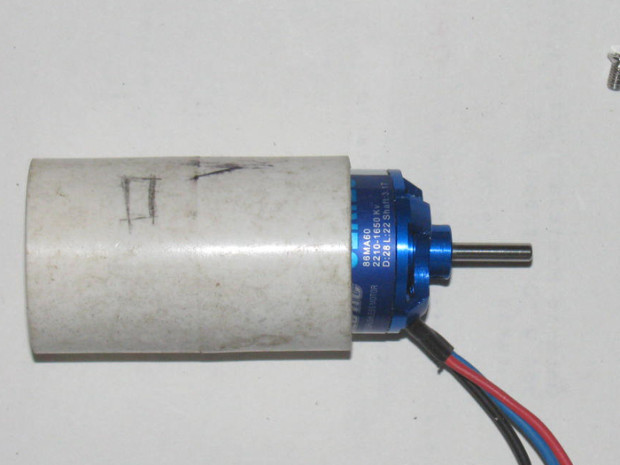
I have a brushless motor that has lots of torque and is small in size.
It will fit inside a 1" plastic pipe connector.
I do have to grind out the inside about 3/32" to get it to slide in.
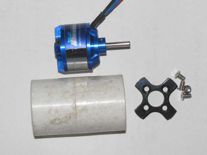
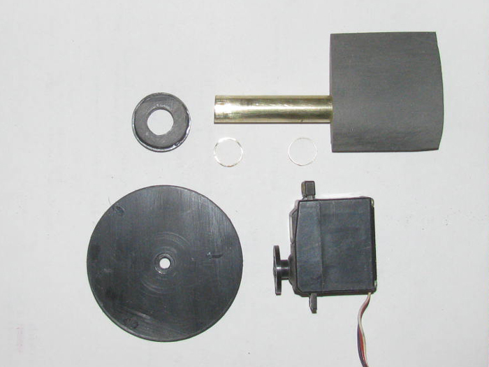
Here is the brushless motor.
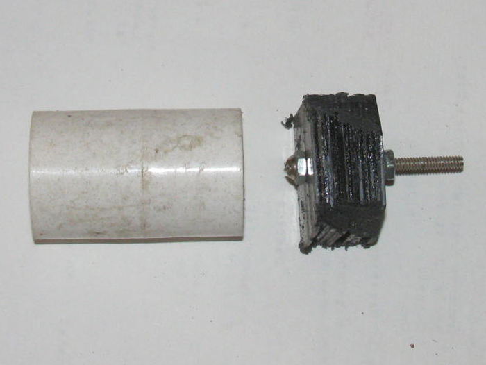
The mounting bracket that came with the motor cut down to fit inside the connector and mounting screws.
The 1" plastic PVC pipe connector.
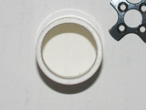
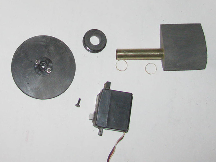
Before grinding on the PVC connector.
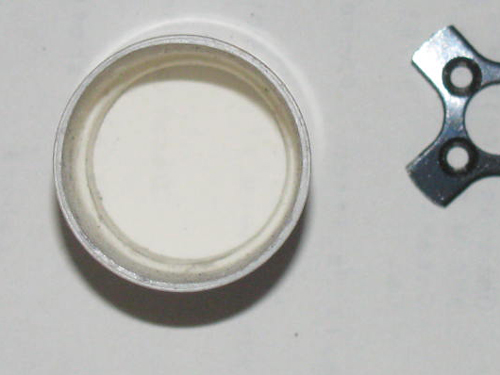
After grinding.
I made a shoulder for the mounting bracket to sit on.
I will epoxy the bracket to the connector.
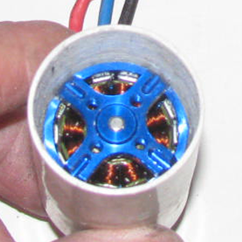
Bracket pushed in to check fit.
Took a couple times to get it down to size.
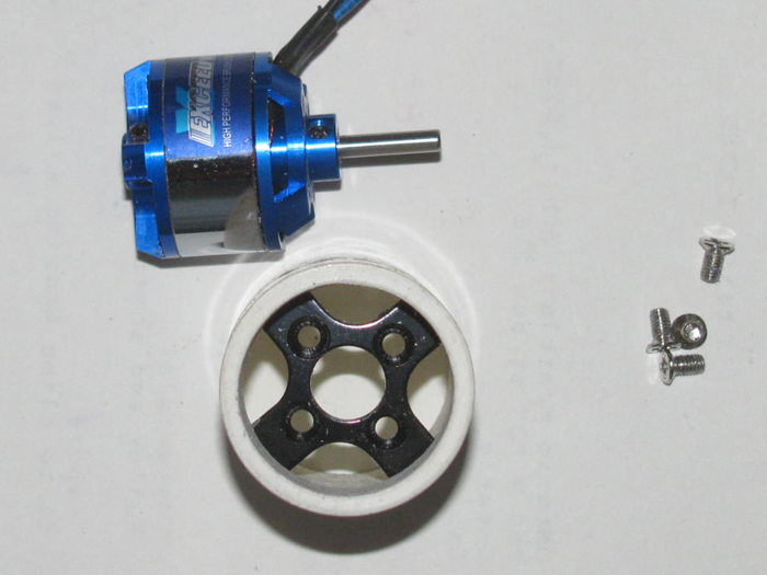
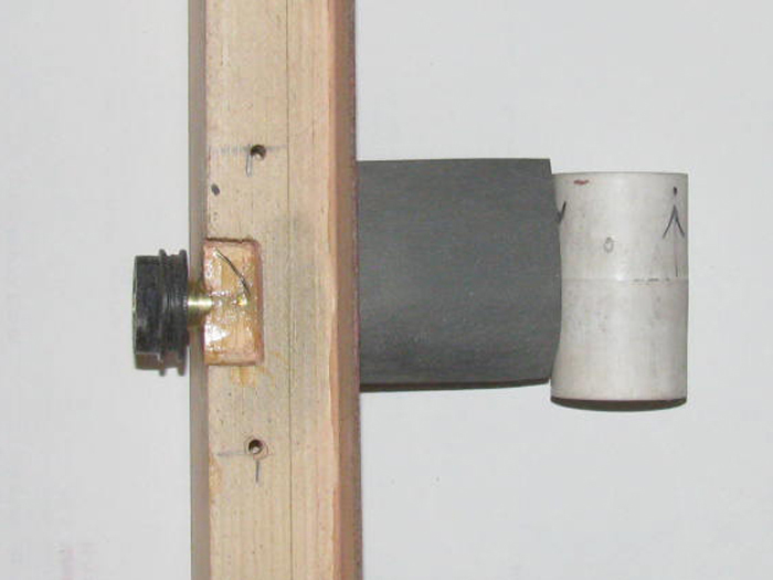
The motor is currently in backwards because the wires are pain to get in the connector and through the bracket.
The wires will come up through a 1/2'" brass tube.
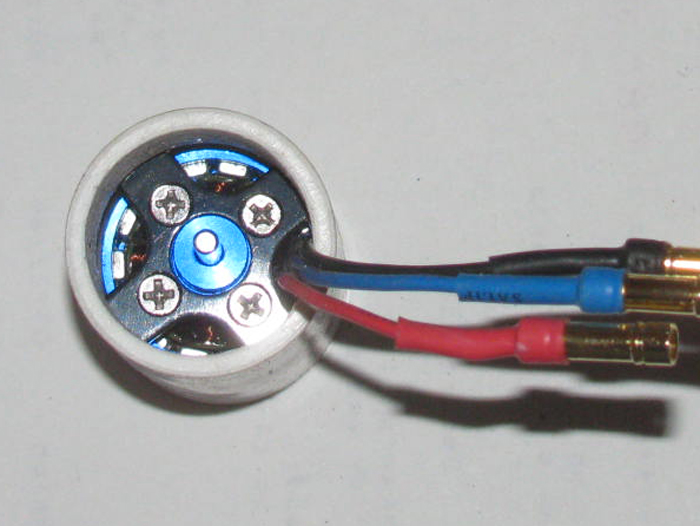
Motor mounted on bracket.
Pushed in to connector to check fit.
I will clean up the inside of the connector with sand paper.
Then I can epoxy the bracket in place.
Something to do tomorrow.
I have also cut a bunch of 1/16" plastic sheet square to make the front of the pod and the rear shaft section of the pod.
The have been cemented up and are in the table vise.
I need to get a cup seal out of the parts box so I know how big to make the tail of the pod.
I will actually wait until the propeller gets here to make the rear section.
I can not post all my builds again but I will try to post my current build.
I will copy from my build logs on my personal web site.
I am not sure whether I post post post for post or put more than 1 post in each post here.
Won't know until I start.
So here goes.
====It started on Nov 14th, 2020==============
Last time out with my Akula II submarine, (Nov 14th) I ran it so long that the BEC cut main power to the propeller motor.
There was no wind that early in the morning.
I had no where to be that was important so I decided to just sit it out until the boat came to shore.
The real question was which way would the wind blow when it came.
The boat was about 150' out from shore but if the wind blew off shore, the boat would go across the lake and it was about 3/4 mile around to the other side.
I got lucky because there is an aerator out about 175' out from shore and this causes a very slight current moving sort of towards shore at about 90 degrees from where I was using the park bench.
Using trees on the far side of the lake, I could see the sub moving about 10' every 15 minutes and in the right directions.
Then I noticed the leaves on the tree above me where starting to move slightly.
Good news, the wind was in the correct direction so far.
From the time I lost main power until I could reach my sub with the antenna I removed from the Tx.
It took about 1 hour 45 minutes.
Got to sit in the park and enjoy the morning. (A bit of stress)
Everything turned out just fine.
This would not have been a problem if I had taken a second boat with me.
I did not.
I also was running alone because this was not a group day to run.
So there where no other boats of any kind to help push the sub back to shore.
While sitting there watching my sub slowly drift towards shore, I thought I needed to bring a second boat every time I go out.
Also thought I might build a rescue boat for just this sort of thing.
Have it with me for me and any one else who might need rescuing.
There have been others that have gotten stuck off shore and needed a push.
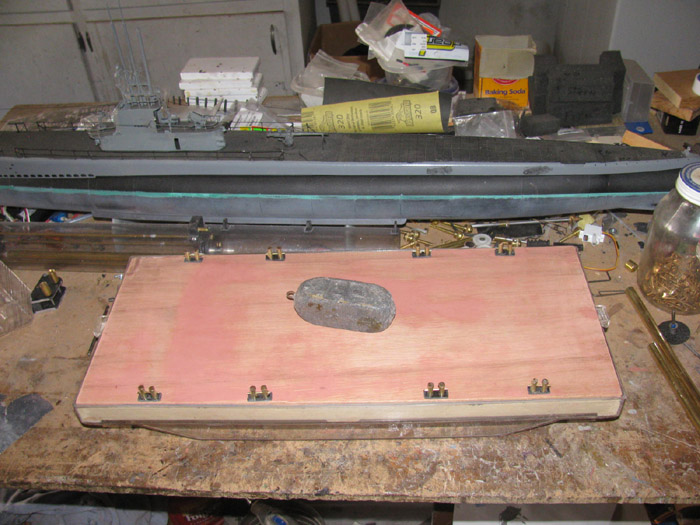
I posted this adventure on Sub Committee and got a response from Greg with attached photos of his rescue barge.
Very simple design and much like I was thinking sitting in the park.
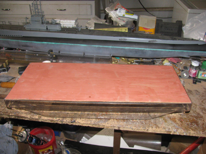
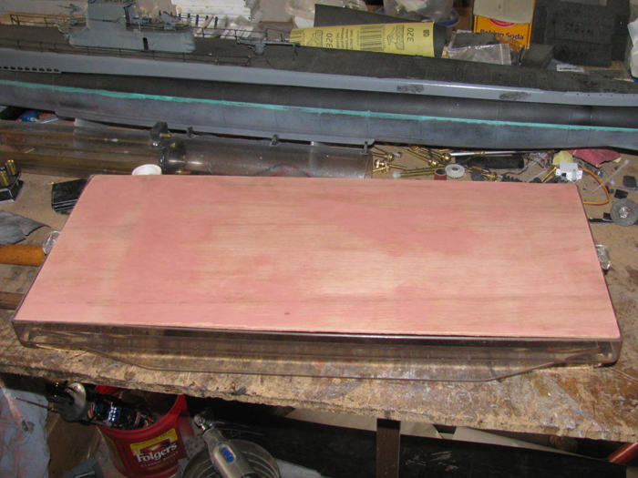
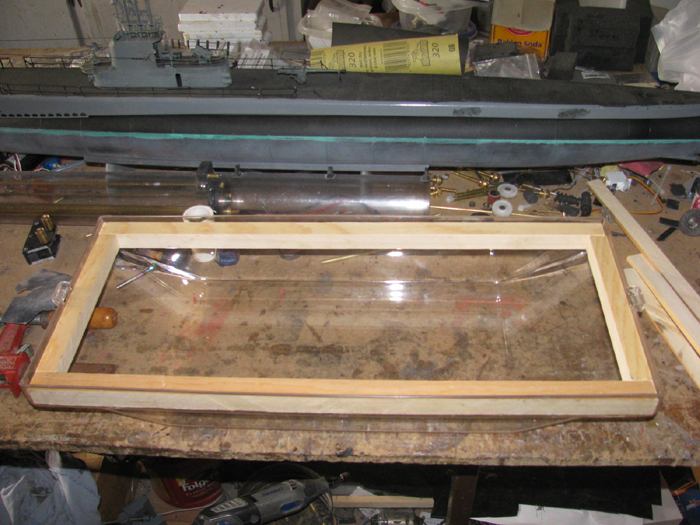
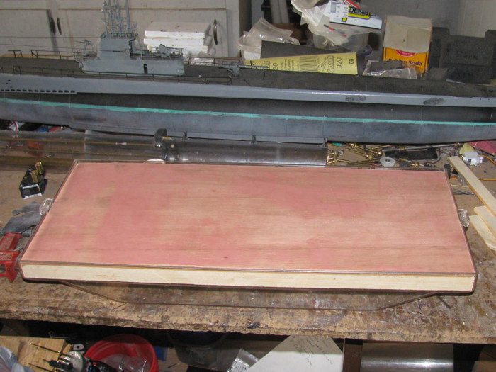
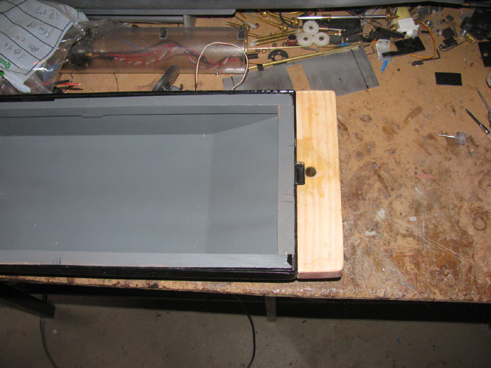
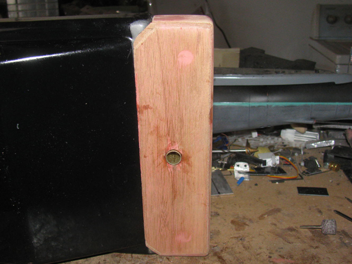
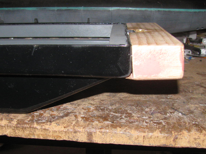
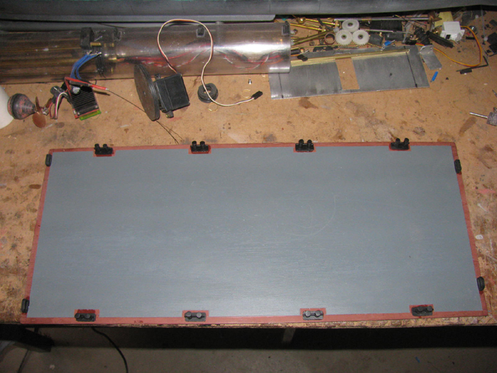
A cement mixing box, square in shape and rounded up are both ends.
Greg made me an offer of a hull like his that I could not refuse.
It arrived with in a few days. (Greg, Thank You)
So here is where the build will start.
====================================
The building of a Rescue Barge.
November 14th =================================================
I looked through my parts box and I think I have everything but a propeller the size I want to use.
I have spare sub propellers but they are either to big or too small in diameter.
I have ordered parts.
Couple of propellers and a couple of dog bone universals. (spares)
I have thought about it.
A propeller with 2 rudders or a Pod hanging below the hull with the motor in it.
The steering linkage is simple.
I can get about 100 degrees from a 60 degree servo using 2 wheels with notches and cable.
I am going to start building a propeller pod.
I have a brushless motor that has lots of torque and is small in size.
It will fit inside a 1" plastic pipe connector.
I do have to grind out the inside about 3/32" to get it to slide in.
Here is the brushless motor.
The mounting bracket that came with the motor cut down to fit inside the connector and mounting screws.
The 1" plastic PVC pipe connector.
Before grinding on the PVC connector.
After grinding.
I made a shoulder for the mounting bracket to sit on.
I will epoxy the bracket to the connector.
Bracket pushed in to check fit.
Took a couple times to get it down to size.
The motor is currently in backwards because the wires are pain to get in the connector and through the bracket.
The wires will come up through a 1/2'" brass tube.
Motor mounted on bracket.
Pushed in to connector to check fit.
I will clean up the inside of the connector with sand paper.
Then I can epoxy the bracket in place.
Something to do tomorrow.
I have also cut a bunch of 1/16" plastic sheet square to make the front of the pod and the rear shaft section of the pod.
The have been cemented up and are in the table vise.
I need to get a cup seal out of the parts box so I know how big to make the tail of the pod.
I will actually wait until the propeller gets here to make the rear section.
Comment