My Rescue Barge

Collapse
X
 
  • Time
  • Show
Clear All
new posts
  • Ralph --- SSBN 598
    Junior Member
    • Oct 2012
    • 1417

    #61
    A servo tester.
    Why, no I do not have a servo tester.

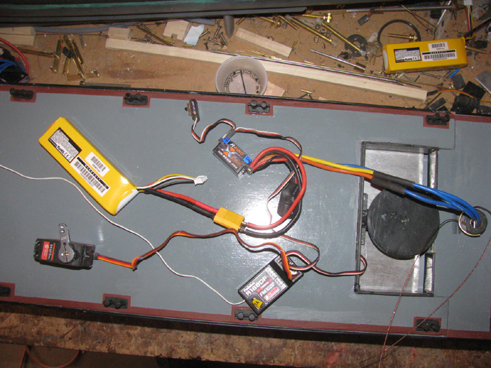
    I do have 2 Tx and a hand full of Rx on the work bench.
    Just a matter of tuning the Tx to the Rx of choice and having a charged battery.

    The Futaba 9CAP Tx is computer controlled and I can turn any channel from zero to 130 % travel.
    I try to not break things, I start at 5% then while everything is on I can turn the percentage up at the Tx to adjust the needed throw.

    My other Tx do not have this feature.

    So basically it requires a little more work to setup.
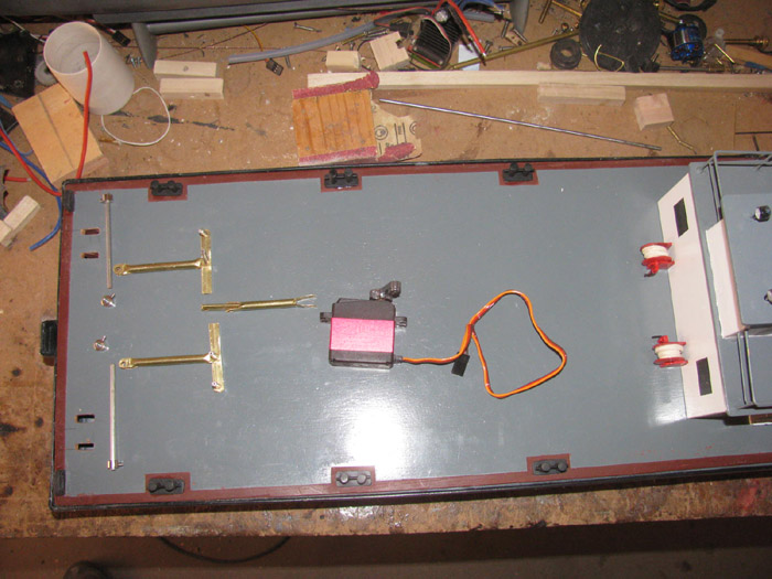
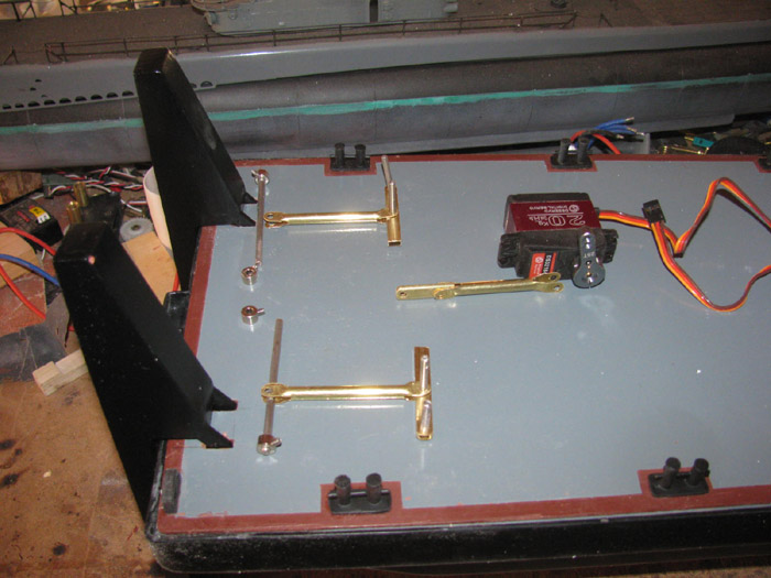
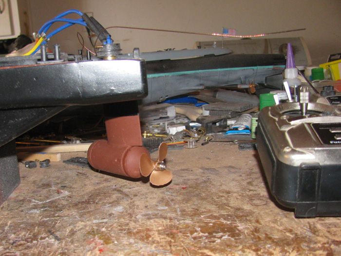
    I will also have to adjust the rudder servo and speed controller because I do not want this boat going very fast at full throttle and I need a little more than 90 degree to each side.

    I do draw on paper the full size linkage and then see how much servo throw I need and this gives me the location of the holes in the horns.
    It is usually close enough with a little adjustment to the Tx.

    My Skipjack was a lot of fun because the Tx is shadered with the Aklula II and all linkage adjustment is physical.
    The Akula II was setup first to the Tx.
    Then I had to match the Skipjack linkage t work on the same Tx.
    No computer in that Tx.

    If I make it to easy, what fun would that be! <GG>

    Comment

    • Ralph --- SSBN 598
      Junior Member
      • Oct 2012
      • 1417

      #62
      January 5th =================================================

      Not able to get out to the shop.
      Just too much to do.

      I spent way to much time looking to brass wheel collars.
      Now that they are hard to find, it was finding a vendor who's web site that could deal with me not having a physical address for billing or delivery.

      Most people do not understand those of us that live out in the desert where there are no street address and mail only is delivered to the post office box.

      I ran the cost numbers for those with free shipping and those with shipping charges.
      Turns out Amazon wins again.
      They had the same parts from the main vendor for a little more than the vendor but they have a fixed shipping cost that is 1/4 the original vendor.
      Cost of parts is more the shopping is much less and that works out that it will cost me $.32 more from Amazon but they take my billing and shipping addresses.
      Parts are on the way for $1.99 shipping.

      Okay, I slipped out to the shop.
      I sanded the primer on the pusher bars.
      2 little spots to glaze again.
      The long seam on the front of the bars where I jointed two bars to make one.
      On both pusher bars, I needed to file a 3/4" line gap where the glue did not push out when squeezed together.
      Applied. Now to let them dry.

      I will paint the pusher bars this afternoon.

      Basically, I am finished with the pusher bars until the wheel collars get here and I can finish the linkage pins.

      What can I do that will not take much time?
      Oh, I can touch up the red paint on the fire hose reels I repairs the valve handle on.
      Done.
      Took longer to clean the brush than to paint.

      When I go out to paint the pusher bards, I will look for wire to wire the pod motor.
      I hope to start assembly of the motor pod tomorrow.

      Today started out with me being confused.
      I thought it was Saturday.
      It was 10:30am before I realized it was Tuesday.
      Got to look at the on screen time and date stuff once in a while.

      oops.

      Comment

      • Ralph --- SSBN 598
        Junior Member
        • Oct 2012
        • 1417

        #63
        Well, I was able to get out to the shop and do some more.

        I was able to finish the other stuff and make back in to the shop.

        Sanded the pusher bars.
        The sun is out and it is warm outside.
        Out to the outside work bench. (it is steel and is very warm)

        I got the first coat of paint on the 3 back sides.

        In to the shop.
        I cut stainless steel pins for the linkage.
        It turned out that the stainless `/8" rod for the shafts and pins was not a shaft at all.
        It is a tube.
        It has a small hole all the way through it. 12".
        Good enough for what I want it for.

        Laid all the parts out on the deck.

        Will continue this when the wheel collars get here.


        This is a rescue barge and I do not want it sinking at any time.
        I have big blocks of white foam from my giant airplane days.
        10' to 15' wing spans.
        Was also going to build an experimental airplane but life toss that out.

        I measured the inside of the hull.
        With my trust old thin hand saw, I cut a piece out of a big block.
        Cut the for and aft bottom angle.

        I measured for the rudder servo and the pusher bar linkage.
        Cutting in to the foam block for the linkage parts.


        Got the needed angles and cuts in the foam and it slips right in under the electronics tray.


        While doing this, I would go out and put another coat on the pusher bars.
        There is more cutting to do but not until I get the equipment installed and I know exactly where to cut recesses in the foam.

        Still painting the pusher bars.

        Okay, touch up the fire hose reels with black handles.


        Temperature is starting to go down.

        Finished painting the pusher bars.
        Set them in place in the deck for a photo.


        Not sure what I will do tomorrow.
        I think I have a couple hours in the afternoon.
        Won't know until tomorrow.
        Could end up with more time.

        Comment

        • Ralph --- SSBN 598
          Junior Member
          • Oct 2012
          • 1417

          #64
          January 6th =================================================

          Okay, what to do?

          How about mounting the speed controller and Rx.

          Set the deck on and mark the access hole under the deck house so I know what my limits are for the electronic parts.
          I put the large servo pulley on and I can now see where to trim the water dam.
          I need to cut away about 2" wide on the back side for the pulley to go over the stern block.
          Dremel and Roto Zip bit does this is a matter of seconds.
          File and sand it so there are no sharp edges.
          I have 3 speed controllers.
          Which one.
          The choice is easy.
          The one I find the programming instructions for first will do.
          Looked under the work bench in a little tray where I put parts taken out of boats during modifications.
          I know they work and this is where the speed controllers came from.
          I know they work because they came out of the several mods on the Skipjack.

          Wait! There is a folded up instruction paper in this little plastic parts tray.
          Instructions for the 30 amp speed controller.
          It is the middle one in size but there is plenty of room for it.

          I have a winner.

          Found some high temperature silicone covered wire that will do for the power down the rudder tube to the motor.
          It is twice the size of the short wires coming off the motor. Not a problem.
          Soldered short lengths, (long enough to get to the speed controller with extra for allowing the rudder to turn 180 degrees.

          Made up a short connector out of two wheel collars and found two 1/8" long stainless grub screws.
          Drill out the wheel collars to accept the brass tube with 1/8" inside diameter.
          Measure and drill hole through the brass tube for the grub screw to go through to reach the motor and propeller shafts.


          The wheel collars are side by side and fit inside the tail cone.


          I have to get this to fit inside the pod tail cone.
          (turns out, the connector with 2 wheel collars fits inside the pod and does not stick in to the tail cone)

          Test fitting the motor.
          The mount is slightly off center in the up and down direction.
          Adjusting the 4 screw tightness did not get the motor to move enough.
          After several test fits, I got out the 1/4" drum sander and Dremel.
          I sanded the inside of the pod housing on the bottom section.
          Tested again and it seems I got it very close.
          Took the Exacto knife and cleaned up the sanding marks.
          That did it.


          Closing up the pod.
          Turns out the 3 screws that were to hold the pod ends on change the straight line enough the shaft would not turn.

          Thought about it and came to the conclusion, I do not need the screws.
          A light coating of silicone glue will hold it on and seal the pod from water.

          I though I needed the screws so if the motor heated up and the air expanded the ends would pop off.
          I did not think it all the way through.
          The rudder shaft is open at the top down in to the pod. (wires)
          It is not a closed system.
          It is vented.
          No pressure build up.

          Using the silicone glue will seal the pod and the silicone should let the pod caps move a little during operation and the shaft should not bind.

          The pod is currently sitting on the bench while some CA glue cures.
          I filled in the 6 screw holes and will file them down later.

          Comment

          • Ralph --- SSBN 598
            Junior Member
            • Oct 2012
            • 1417

            #65
            January 7th =================================================

            This afternoon, I sanded the CA that I filled the bolt holes with on the motor pod body.
            Painted the pod below the waterline including the nose and tail cone. (guess where the waterline might end up)
            Let it dry.

            While it dried, I wired up the main power from the battery to the speed controller.
            Required 3 plugs and 2 wires about 6" long.
            Checked all in the hull and soldered the plug ends on the wires.


            Finished this and went back to painting the above the waterline on the pod assembly, hull black.
            I am going to let this dry completely before putting the motor back in the pod body.

            Comment

            • Ralph --- SSBN 598
              Junior Member
              • Oct 2012
              • 1417

              #66
              January 8th =================================================

              The motor has been installed in the pod housing.
              The propeller has been put in place so I can measure the propeller shroud.
              The should was made out of a pvc water pipe connector.
              I had sanded the inside until the propeller fit.

              Today, I wanted to fit the shroud over the propeller and see where to cut the length.
              The connector is 2.5" long.
              After I sanded more on the inside to get the propeller to pass through without touching, I fit it to the rudder and measured the shroud.
              I had already cut a notch in the shroud for the back of the rudder.
              Should have waited but I didn't.
              To get the propeller shroud in place and look the way I want it, compared to the many photos I looked at, I needed to cut 1/4" off the front and some off the back.

              The shroud is now 1 5/8" long.
              After cutting to length I needed to turn the inside some more and shape the outside.
              Out to the tool shed and on to the drill press.
              No I do not have a chuck big enough to put the connector in.
              So like last time, I tightened up the chuck with nothing in it and then using electrical tape, I wrapped the bottom end of the chuck until I could push the connector on to the tape and it was tight.
              This works well to spin the connector.
              Now with Exacto knife to cut inside plastic out and the outside as well, I worked the inside to get the propeller to fit and then I shaped the outside to an airfoil look.

              Sanded with fine sand paper before removing from drill press.

              Back to the shop.
              I had a piece of plastic on the bench that was several layers thick.
              I have been moving it around for several days.
              I had made this part way back when.
              Now it is time to cut it in to 4 pieces and shaping.
              These parts will become the 3 shroud support pieces.
              From the pod body to the shroud.

              I got them cut and shaped roughly.
              I have to drill bolt holes before going any farther.
              Going to work on that tomorrow.
              Today I was able to get 1.5 hours in the shop.

              Comment

              • Ralph --- SSBN 598
                Junior Member
                • Oct 2012
                • 1417

                #67
                January 9th =================================================

                Early start this morning.
                My plan is to get the motor pod assembled.

                Here I have drilled the shroud and installed the 3 shroud supports to the shroud.
                The propeller is there to make sure I center the propeller and there is clearance.


                Another view of the motor pod and shroud.


                The propeller shroud has been installed.
                I found that a 1/4" drill bit was the correct spacing from the pod to the shroud.
                Drilled, tapped and installed bolts to hold shroud to the pod.


                A view inside the shroud showing propeller clearance.


                Now to disassemble it all and shape the supports to make them a little more streamlined.
                Got to remember to number them so they go back in the same spot.
                Also I have to recess the bolts at the pod end.
                This was all drilled by hand with no jigs.
                ----------------------------
                Disassemble.
                Shroud supports filed and shaped.
                Shroud and supports are now painted hull black.

                The nose and tail cone have been installed using silicone glue.
                I will let the silicone cure over night.
                I will re prime the motor pod.

                Then I will install the propeller and the shroud on to the pod.
                This should complete the motor pod drive and be ready for testing.
                Last edited by Ralph --- SSBN 598; 01-09-2021, 06:42 PM.

                Comment

                • Ralph --- SSBN 598
                  Junior Member
                  • Oct 2012
                  • 1417

                  #68
                  January 10th =================================================

                  I started by checking the pod for leaks.
                  This was simple.
                  I just had to draw a air out from the top of the rudder post.
                  I could not draw any air at all.

                  Now to continue with the assembly.
                  Right after I paint the pod and shroud.

                  Got that done.
                  Here is the pod installed in the stern block.
                  The hole you see is for the shroud.


                  Here the shroud is slipped on to the pod.
                  I have not yet put the bolts in.
                  I want to get another coat of paint on the shroud before installing the bolts.


                  With the pod installed the top pulley is in place.
                  The keep ring is in place.
                  I can now start on the steering cable.

                  Drilled some holes for the cable to go through the sides of the pulleys down in to the pulley groove.
                  I measured for the cable and cut a length.
                  This cable is what I use as rigging on sail boats.
                  It is fishing wire leader at about 250 pound strength.
                  It should do fine.

                  The cable tensioner is done but not installed.
                  I want to finish painting before I install the cable and stretch it to tension.
                  The plastic pieces will mount on top of the large pulley at the front.
                  The adjusting bolt with be on the outside of the pulley so I can reach it with a small screw driver.
                  I probably could have set it on the pulley for the photo.


                  Later today, I should get the shroud painted and mounted.

                  Yea, I am going to have to build a stand before I damage the pod and shroud.
                  I will measure the barge and see if I have enough lumber to make a stand and maybe a transportation box.

                  Comment

                  • Ralph --- SSBN 598
                    Junior Member
                    • Oct 2012
                    • 1417

                    #69
                    The shroud has been painted and mounted.

                    Might as well measure the barge for a transportation box.
                    Got the measurements.

                    Came in the house and measured the boxed my other boats are in.
                    I was surprised.
                    The barge box would need to be 12" tall.
                    My Skipjack box is 12" tall.
                    The box would need to be 28" long.
                    This is shorter than my George Washington box by 7".
                    And the box would need to be 12" wide.
                    My widest box is for my Akula II at 9.5".
                    The barge would be 12" wide.

                    So all in all, it is not a big box at all.
                    Just wider by 2.5" but much shorter than all of them.

                    Not to mention my Gato box is more than twice as long at 57".

                    Tomorrow, if I find time, I will go through the wood stack to see if I can do this.

                    I am done outside.
                    The wind has turned colder than I like without a jacket.

                    Comment

                    • Ralph --- SSBN 598
                      Junior Member
                      • Oct 2012
                      • 1417

                      #70
                      January 11th =================================================

                      In the shop after noon.

                      I am going to see if I can use the 5 channel Rx I found in my parts box.
                      It was given to me.
                      I soldered the speed controller to the motor wires.
                      I can now get power to the Rx by the 3 wire connector.
                      Plugged it in.
                      Also plugged in the rudder servo so I could see if the Rx was connecting.

                      I tried to get the 5 channel Rx to connect to the Tx.
                      Problem for me is there are no instructions.
                      Another problem for me is I only know how to turn on the electronics and work on simple issues.
                      Speed controller to e is not simple.
                      There a beeps that I can not hear or they are too close together for me to break down.
                      This Rx just beep continuously.
                      No matter what I do, it only beeps none stop.
                      It may be a matter of Tx and Rx not being compatible.

                      My solution is to get my 8 channel Rx that goes in my GW which happens to be all a part right now.
                      Plugged it in and it came to life.
                      Checked the Tx channel percentages and set them to 100%.
                      Rudder servo, not connected to rudder control horn, works fine.
                      Next, I tried the speed controller channel.
                      Forward, good.
                      Reverse works but is slower that forward.
                      Had this issue when this system was in the Skipjack.
                      It also requires a pause at neutral to change direction.
                      Reason I took it out of the Skipjack.
                      Anyway, it works correctly.

                      Now to try the very high torque servo I will use for the pusher bars.
                      Holy crap!
                      It works and the torque is enough to push start my real truck.

                      Okay, testing works as it is suppose to.
                      Even the servo directions are correct.

                      Next is to install the speed controller and Rx on to the electronics tray.
                      Clean up the wiring.
                      Shorten some of the wires and resolder.

                      I tried to take a photo of the propeller turning.
                      Did not work out.
                      The camera actually stop motion the propeller.
                      Looks like a stopped motor shot.
                      The propeller is turning at a speed that my eyes sees only a blur.
                      Camera stopped it. (I am amazed)


                      Here are the electronics sitting on the deck.

                      Comment

                      • Ralph --- SSBN 598
                        Junior Member
                        • Oct 2012
                        • 1417

                        #71
                        January 12th =================================================

                        After think about the speed controller I have( 3 of them), I know from running it in the Skipjack, I do not like the neutral pause to change directions.

                        I order 2 new speed controllers that do not have the pause so they say.
                        It is going to take some time to get here. (4 to 6 weeks)

                        Out to the lumber pile.
                        I found enough plywood to make all 6 sides of a transportation box.
                        Measured the barge again t make sure of the numbers.
                        Cut theplywood panels.

                        Looked around for trim boards.
                        I have about 3' which will not do.
                        I need 42' in all.
                        Next time I am near the lumber store, I will get what I need.

                        Back in to the shop to work on the steering system.
                        I got it all measured out and ready for testing.

                        Began the testing.
                        It was working very well up until, the cable started jumping off the pulley groove and falling down on the shaft.

                        This will not do at all.
                        Looking at the cable while running the servo, I see the servo turn the large pulley and take a strain on the cable.
                        For an instant the rudder shaft does not turn and the cable on the opposite side becomes slack enough to jump off the small pulley.

                        Farther looking says it is not slack at all.
                        It is the cable is so stiff that it does not bend around the pulley and then jumps off.

                        The cable is 250# fishing leader wire.
                        It does not have to bend to do the job it was made for..

                        I tried bending the wire in to a curve.
                        Seemed like it would work.
                        The cable goes around the pulley but the curve is so stiff it comes off the pulley as it turns and is still curved.

                        This will not do.

                        So I removed the cable and I am going to test some pre stretched braided nylon string.
                        Rated at 200 #.

                        Okay, I tried to stretch it.
                        I could not.

                        I am going to try this on the pulleys.

                        But I think I will make some small changed to the pulleys.
                        I will remove the bottom edge of the pulley by turning it to the size of the groove.
                        Then I will glue another piece of sheet plastic on and make the edge wider.
                        Maybe this will catch the string before it can run off the pulley on the bottom.

                        Pulleys have been turned are now in the vise with the new sides on them.

                        Comment

                        • scott t
                          Member
                          • Feb 2003
                          • 880

                          #72
                          Ralph, How about using an O-ring for the pulley belt?

                          Comment

                          • Ralph --- SSBN 598
                            Junior Member
                            • Oct 2012
                            • 1417

                            #73
                            Thanks, Scott.
                            If what I am doing now fails, I will try o-ring next.

                            Comment

                            • Ralph --- SSBN 598
                              Junior Member
                              • Oct 2012
                              • 1417

                              #74
                              January 13th =================================================

                              Changes to the pulleys have been made.
                              I have fitted them but not tested them.

                              Assembling the transportation box has started.
                              The panels where cut yesterday.
                              Today, I cut most of the trim boards.
                              Before I can cut any more, I need to assemble the sides and ends.

                              So, clamped on the outside steel work bench I have the 2 sides with the top edge trim in place.

                              Building these boxes is time consuming.
                              They are glued together with no nails of screws.
                              I have to clamp and let cure each trim board.
                              Takes lots of clamps.
                              I can do 2 maybe 3 panels at a time.

                              It will take a few days but I am now waiting for parts to start showing up.
                              End of month for some and first part of March for others.

                              Comment

                              • Ralph --- SSBN 598
                                Junior Member
                                • Oct 2012
                                • 1417

                                #75
                                January 14th =================================================

                                More assembly of the transportation box.
                                I cleaned up the excess glue from yesterday.
                                I have the 2 sides glued and clamped.

                                In to the shop.
                                Thought I would install the shroud.
                                Looks like I need to do some fitting.
                                That will have to be later today.
                                Got things to be done away from home.
                                -------------------------

                                Comment

                                Working...
                                X