1/72 Revell Gato Balao conversion-first time cylinder (yeah, I'm at a loss)

Collapse
X
 
  • Filter
  • Time
  • Show
Clear All
new posts
  • southern or
    Junior Member
    • May 2014
    • 484

    #16
    Originally posted by salmon View Post
    I had the same concerns and opted not to put brass deck on, but another gentleman informed me that it ended up weighing the same or less. I do not remember what configuration he used to support the deck or how much he left on as a whole, but then I do not recall if I saw him ever sail his sub. So, ultimately it is up to you. This boat is your boat to choose as you want to. I will be watching because when I get around to building my second Gato (still a ways away) it will be a Balao too. So, I am learning from you!
    You might be learning from my mistakes, lol. I'm not going for an exact boat, but it might be close to the Ling since I'm using the stencils for her limber holes and I think she even had this conning tower. Some of the Tench and Balao boats had the anchor on the other side. I have the stencil to move it, but I decided against it.

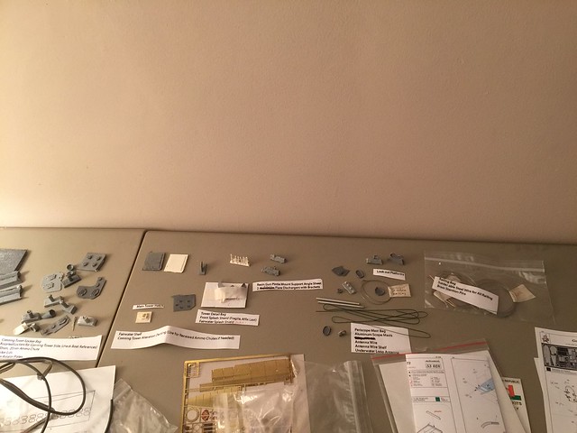
    Stencils, replacement gun, and tower all came from Iron Bottom Sound. I can't remember, but I think I got the 'Government Long Balaos' tower. You'll still be using some of the Revell kit parts on it since it isn't a 100% replacement. The Sub-Driver and fittings kit came from Bob at Nautilus Drydocks, but he did announce that they'd stop carrying them so he might not have them anymore, so It'd be something to ask him.

    Comment

    • southern or
      Junior Member
      • May 2014
      • 484

      #17
      Alright, minor update. Bob got the rest of the parts for the driver out to me so I'm pretty sure I have everything I need to set it up now-aside from wire insulators. I did order the DVD set and that should be here by the end of the week-maybe. I have a small town not real postoffice so anything can happen. I'm tempted to start on the filling and drilling of the limber holes while I wait though. IBS recommends full deck assembly before you apply the stencils, but I don't have a tub and you need to soak the deck to get them off-so it'd be better if the deck is still in sections because of the kitchen sink. Tower is coming along and the snorkel fits almost perfectly.

      Comment

      • southern or
        Junior Member
        • May 2014
        • 484

        #18
        Alright, another quick update. Tower is hollow now and it's really light now (before I add all the bits). I'm working on my game plan for how I'm going assemble and then cut the hull (thanks Bob) and noticed that the bow tube doors are cast into the bow so now I guess I need to decide if I want to add torpedoes down the road now. I built Revell's type VII and type IX and they all have optional doors.... Clearly I wasn't paying attention when I built another Gato as practice because this problem isn't in my notes. Still working on the tower obviously.

        Still needs a lot of work and the resin casts need attention.


        More IBS cast parts. *Not all of these parts are for the tower.

        Comment

        • salmon
          Treasurer
          • Jul 2011
          • 2327

          #19
          This will be a beauty!
          You have all the bits and pieces to make a wonderfully detailed working r/c sub. Will you done by summer?
          If you can cut, drill, saw, hit things and swear a lot, you're well on the way to building a working model sub.

          Comment

          • southern or
            Junior Member
            • May 2014
            • 484

            #20
            Originally posted by salmon View Post
            This will be a beauty!
            You have all the bits and pieces to make a wonderfully detailed working r/c sub. Will you done by summer?
            I hope so, but if I'm as busy as I have been the last few weeks I might have to push it out. I did get some amazing reference materials when I had 10 minutes to myself though. The first is "US Submarines 1941-45" by Jim Christly (ISBN-978-1-84176-859-5) and "The Fleet Type Submarine" (ISBN-978-1-4116-7753-1) which is a scan and print of the June, 1946 NAVPERS 16160 Sub School training manual that used USS Perch (SS313) as the reference ship. Seems Perch had external underwater sound equipment by the keel aft of the diving planes and ballast tank flooding ports in front of the sound gear.

            Comment

            • southern or
              Junior Member
              • May 2014
              • 484

              #21
              Alright, I've got my hull sections cut so I'll be working on getting some of it setup soonish. I'm going to need help placing and setting up the Fittings kit as I go because I don't have placement or setup instructions for them. Also, What should I be doing NOW to set her up for possible torpedoes in the future (aside from cutting the doors open)?

              Thanks!

              Comment

              • southern or
                Junior Member
                • May 2014
                • 484

                #22
                Alright, I "Think" I know were most the fittings go now, but I have some questions about a few parts and the sub driver still.

                for the driver, 1, would it be acceptable to run 24 gauge wire from the ESC's on/off terminals in the aft to the built in on/off switch in the front, or is the forward switch hole meant to be used for a positive battery switch only? 2, my servos don't seem to fit in the ready made slots and I'm wondering if anyone else has had this problem. 3, If one servo is for the forward dive planes, and one is for the aft ones, with a third one for the rudder, what's the 4th control arm hole for? Also, is there any harm in removing the cover from a top down plug (radio) receiver in an attempt to make it fit? 5, there is a positive and a negative wire coming off what I think is the air solenoid. Do they get wired into the battery feed directly?

                As for the fittings, Not 100% on where the "Swing-arm operating shaft retainers", "Retract mechanism swing-arm", "bow plane and torque tube bell-cranks", "Torque tube retaining collar", "torque tube support bearings", and "Rudder operating shaft bell-crank" go. Can upload pics if it helps.

                Thanks
                Last edited by southern or; 01-07-2018, 01:37 AM.

                Comment

                • southern or
                  Junior Member
                  • May 2014
                  • 484

                  #23
                  Originally posted by southern or View Post
                  Alright, I "Think" I know were most the fittings go now, but I have some questions about a few parts and the sub driver still.

                  for the driver, 1, would it be acceptable to run 24 gauge wire from the ESC's on/off terminals in the aft to the built in on/off switch in the front, or is the forward switch hole meant to be used for a positive battery switch only? 2, my servos don't seem to fit in the ready made slots and I'm wondering if anyone else has had this problem. 3, If one servo is for the forward dive planes, and one is for the aft ones, with a third one for the rudder, what's the 4th control arm hole for? Also, is there any harm in removing the cover from a top down plug (radio) receiver in an attempt to make it fit? 5, there is a positive and a negative wire coming off what I think is the air solenoid. Do they get wired into the battery feed directly?

                  As for the fittings, Not 100% on where the "Swing-arm operating shaft retainers", "Retract mechanism swing-arm", "bow plane and torque tube bell-cranks", "Torque tube retaining collar", "torque tube support bearings", and "Rudder operating shaft bell-crank" go. Can upload pics if it helps.

                  Thanks
                  I found Salmon's threads on Sub-driver and now I have a few answers and more questions. Like, where is the proper placement of the driver, what tools and parts do I need to extend the dumas couplers, what parts do I need to make the control rod assemblies/how do they go together to make the forward planes work, what parts are needed to make the dive plane retractor work...

                  I do really well with instructions but all I have are a bunch of parts yet I'm thinking I'm still missing a bunch of material now. If this was going to be static it'd be done last month.

                  I've got a pair of Durbro 109 Kwik Link Clevis' in the mail, a bunch of .7mm brass rods (.5 sold out), and some hook and loop tape.

                  Comment

                  • Ralph --- SSBN 598
                    Junior Member
                    • Oct 2012
                    • 1417

                    #24
                    I believe these to be the original build reports for the Revell Gato using the SubDriver.

                    Link located on The Nautilus Drydock web site.

                    Comment

                    • salmon
                      Treasurer
                      • Jul 2011
                      • 2327

                      #25
                      The proper placement that David Merriman gave me was about 3” of space from the end of the WTC Dumas connectors and the propellor shaft Dumas connectors. You will need to shorten the WTC and don't do what I did and make all the cut off material just in the battery section. Divide the amount you need to remove between the front and back of the cylinder. You will then be able to get larger batteries.
                      Let me respond better once I get to my computer instead of the iPad.
                      If you can cut, drill, saw, hit things and swear a lot, you're well on the way to building a working model sub.

                      Comment

                      • salmon
                        Treasurer
                        • Jul 2011
                        • 2327

                        #26
                        O.K., to extend dumas dogbone, I found an aluminum tube that slid over the nylon dog bone (which I cut in half). Using an xacto knife score the aluminum tube all around.
                        Click image for larger version

Name:	DogBone01.jpg
Views:	1
Size:	37.1 KB
ID:	130457
                        Once that is done bend the tube at the score and it will snap off along that line.
                        Now you should have something like this:
                        Click image for larger version

Name:	DogBone02.jpg
Views:	1
Size:	35.4 KB
ID:	130458
                        Then I drilled through the tube and nylon dog bone with a 1/16" drill bit. I found it easier to drill a hole first, then assemble and using that hole as a guide drill all the way through it (I did this with a hand drill). Once that is done I push a 1/16" brass rod into the hole.
                        Click image for larger version

Name:	DogBone03.jpg
Views:	1
Size:	36.0 KB
ID:	130459
                        I cut the rod so it is 1/16th to 1/32" proud on each side. With a hammer and small anvil I pound on the 1/16" rod so the ends mushroom out (peen both sides alternating every so often).
                        Click image for larger version

Name:	DogBone05.jpg
Views:	1
Size:	32.9 KB
ID:	130460
                        Then I file each side to make it less proud.
                        Click image for larger version

Name:	DogBone04.jpg
Views:	1
Size:	30.4 KB
ID:	130461

                        The bow plane I use a long 1/16" rod that goes to the aft of the sub. I have a Z bend at the bow plane and one of David's magnet connectors on there. The long rod has magnetic connector on each end. I think I have this on my build (I am Salmon on SubDriver sire). Please let me know what else you need help on. Take it in steps and do not feel overwhelmed we can get you up and running.
                        Are you ready to install the Sub-Driver?
                        Last edited by salmon; 01-07-2018, 03:29 PM.
                        If you can cut, drill, saw, hit things and swear a lot, you're well on the way to building a working model sub.

                        Comment

                        • southern or
                          Junior Member
                          • May 2014
                          • 484

                          #27
                          Thanks guys.

                          What I have done so far: the central hull is cut as is part of the aft hull-but no parts are joined yet (band saw isn't wide enough for a complete hull). I already know I need to remove/modify the stock holes and mount points for the dive planes and rudder so they can work.

                          The driver: I'm filing away at the servo housing so they fit. As for parts going in it: 1 10A Mtroniks ESC, a Battery and link monitor, 4 servos and the solenoid. I'm still using NiCad batteries. I doubt I have the skills to cut the WTC and still have it function so it will need to work as is-plus I can't for the life of me find a 8ch 75mHz Futaba receiver that ISN'T a top down plug configuration so the ones I have that are 2"x1"x.5" are what I 'get' to use. Plus if I want to add torpedos later on I'm most likely going to need a decoder and that's bigger then the receiver. I'm not sure where I could find 3" to cut even if I had the confidence to. It looks like I have room to move it forward with enough room left over for the control rods. Could I just use foam and lead to compensate or was there another reason for the removal of 3"?

                          For the dog bone it's looking like I'll be needing a tube that's just over .5" right?

                          My ESC.

                          Do these go directly to the battery feed before the ESC for the solenoid?

                          Battery fits with just enough room for a decoder should I need it down the road.

                          One receiver with the cover off and one stock.
                          Last edited by southern or; 01-07-2018, 07:11 PM.

                          Comment

                          • JWLaRue
                            Managing Editor, SubCommittee Report
                            • Aug 1994
                            • 4281

                            #28
                            Originally posted by southern or View Post
                            .....plus I can't for the life of me find a 8ch 75mHz Futaba receiver that ISN'T a top down plug configuration.....
                            .....SubTech has a side pin out receiver that is Futaba compatible, though it's 'only' 7 channels. Perhaps this would work?
                            -Jeff
                            Rohr 1.....Los!

                            Comment

                            • southern or
                              Junior Member
                              • May 2014
                              • 484

                              #29
                              Originally posted by JWLaRue View Post
                              .....SubTech has a side pin out receiver that is Futaba compatible, though it's 'only' 7 channels. Perhaps this would work?
                              -Jeff
                              Email sent to Matt. Thanks Jeff.

                              Comment

                              • southern or
                                Junior Member
                                • May 2014
                                • 484

                                #30
                                Originally posted by Ralph --- SSBN 598 View Post
                                I believe these to be the original build reports for the Revell Gato using the SubDriver.

                                Link located on The Nautilus Drydock web site.
                                Those PDFs are really REALLY helpful. Thanks! I'm still going through them since there is a lot there.

                                Comment

                                Working...
                                X