Well thanks, BD!
A couple weeks
Well thanks, BD!
A couple weeks back, I worked on cutting out the many ballast tank flood holes. I chose a pattern after digesting the great input presented in the flood hole thread, and forming a composit from all the info. Thanks to goose814, I was able to reduce the work considerably because the fuel/ballast tanks had flood valves which would normally be closed, and these need only be scribed. Similarly, the fuel oil tanks had no ports, only covered manholes, which could also be scribed. Primarily, the main ballast tank flood ports needed to be opened. Still, there were 36 of them, plus 2 openings to the safety tank well, 1 for the negative tank well, and 2 for the retractable WCA sonar projectors. I referred to The Fleet Type Submarine, an online version of the original training manual, to determine which tanks and ports where which.
From the drawings available, the free flood ports looked to be oval (not elliptical) slots. These could each be drawn as a pair of overlaping circles, connected by two straight tangent lines.
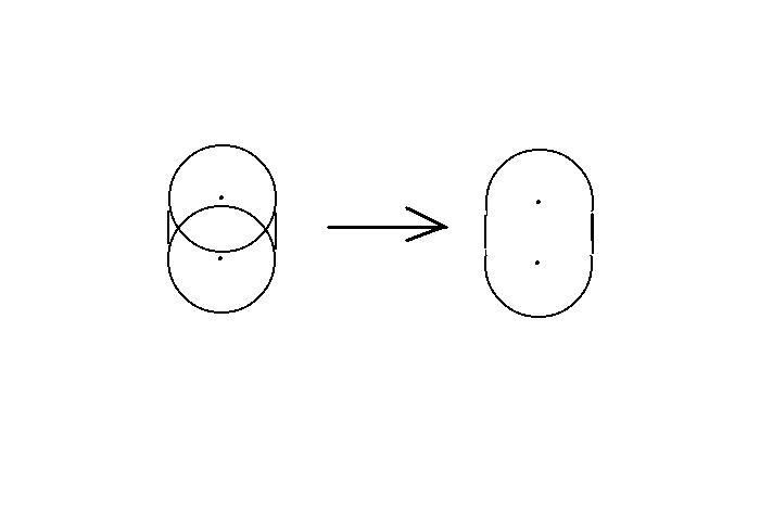
All I needed to do would be to locate the centers of these holes on the hull and drill them out. Then just file the sides between them straight.
I also noticed that 32 of the ports were located in 4 groups of 6, and furthermore, that each group was spaced the same way. If I had a template to locate the centers of each port relative to the keel, I could drill small pilot holes in the correct locations and then enlarge them. Moreover, I could put 3 pairs of holes on one template and get consistent hole spacing for all the ports in a group on each side of the keel.
Now if I still had convenient access to a milling machine, it would be a simple matter to precisely locate all the pilot holes in question. But this is not the case. I do, however, own an antique metal lathe which has calibrated handwheels that are used to move the top-slide and cross-slide on the tool bit carriage. Hmm….
I bolted my portable drill press to the lathe table top, positioning the drill chuck right above the carriage and presto]http://i119.photobucket.com/albums/o130/Crazylvan/IndexingDrill.jpg[/img]
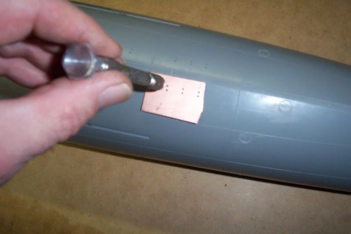
Using a #65 drill bit, I made several drilling templates to accommodate the various hole patterns required.
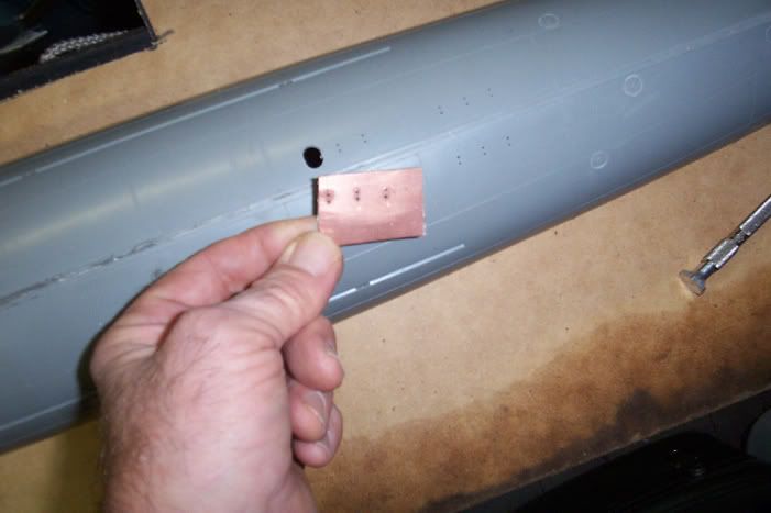
To do a set of flood ports, the drill template is held against the keel in the correct fore and aft location. The #65 bit is relocated to a pin vise, and the hole pattern is transferred by hand to the relatively soft plastic hull in short order. If you right click and view image, you can see here the pattern of the previously drilled pilot holes.
If I had tried to enlarge the pilot holes to the final size using an ordinary twist drill, the results would have been disastrous, as this type of bit will catch on the plastic and rip it up badly. Instead I made a simple tool to do the job cleanly. It consists of a length of K+S brass tubing, having an OD the same as the desired hole size. One end was sharpened by running an Exacto-knife around the inside edge, then small teeth were cut around the circumference to create a small hole saw. A short length of brass rod which is the same size as the ID of the tubing was center drilled in the lathe to accept the #65 bit, thus forming a centering guide for the hole saw. It all fits together like this]http://i119.photobucket.com/albums/o130/Crazylvan/Toolsketch.jpg[/img]
Here is the actual tool]http://i119.photobucket.com/albums/o130/Crazylvan/Tool.jpg[/img]
The guide pin is inserted into the pilot hole]http://i119.photobucket.com/albums/o130/Crazylvan/Centerguide.jpg[/img]
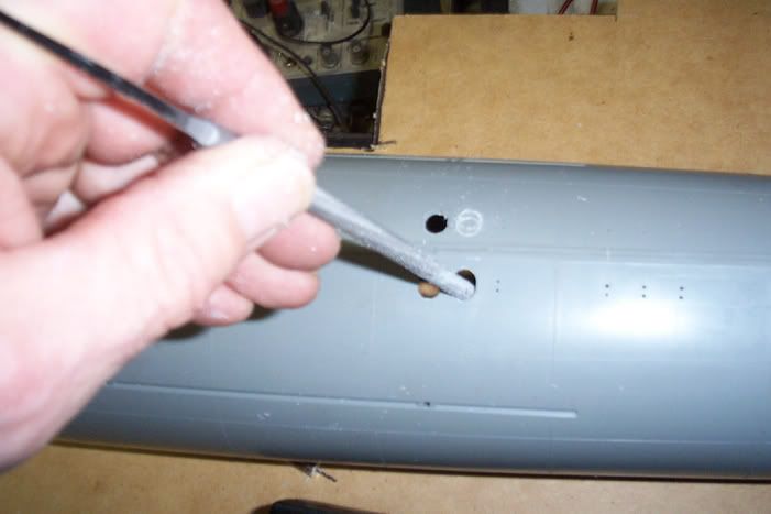
The hole saw is then mounted in my portable drill, placed over the guide rod and run at slow speed with moderate pressure so as not to melt the plastic. I did not punch through in one shot, but alternated several times between the two ends of the port to prevent one side of the port from collapsing out from under the saw before the other.
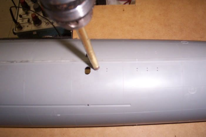
The result is a hole shaped something like a fat figure 8. A file is then used to flatten out the sides.
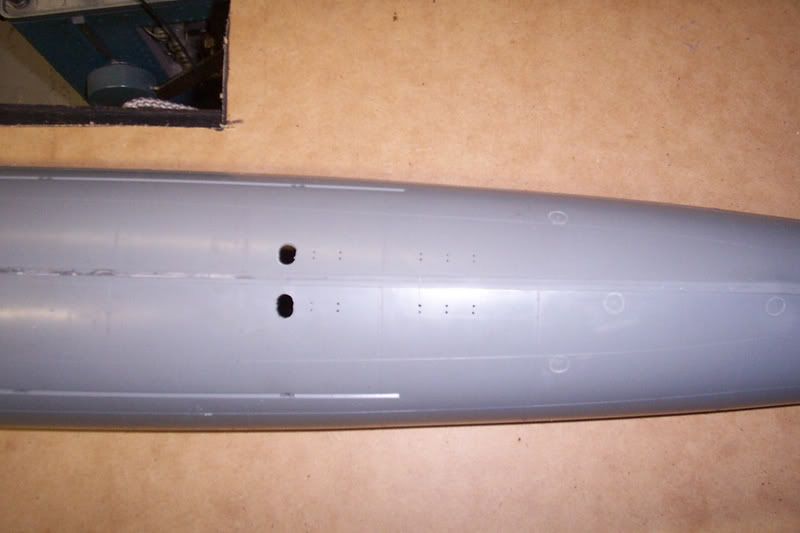
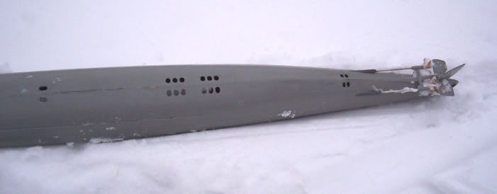
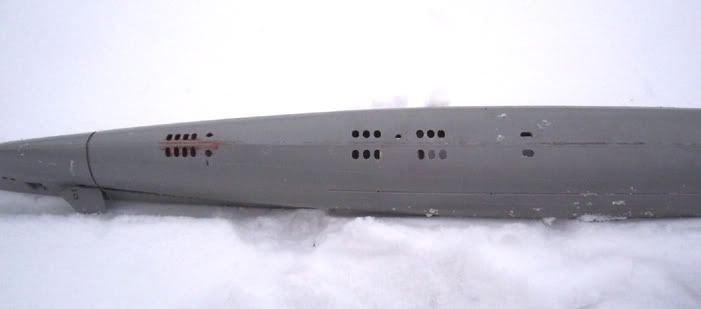
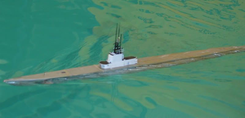
The completed free flood ports.
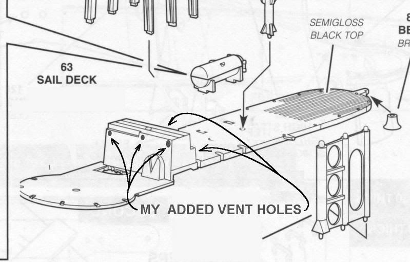
I have scribed in several fuel tank manhole covers, but not the fuel/ballast tank valves. After studying the various available drawings and photos, I am uncertain whether they are circular, oval or elliptical. The Fleet Type Submarine online manual describes them as rectangular. I will wait until I can resolve this and scribe them in later.
A couple weeks
Well thanks, BD!
A couple weeks back, I worked on cutting out the many ballast tank flood holes. I chose a pattern after digesting the great input presented in the flood hole thread, and forming a composit from all the info. Thanks to goose814, I was able to reduce the work considerably because the fuel/ballast tanks had flood valves which would normally be closed, and these need only be scribed. Similarly, the fuel oil tanks had no ports, only covered manholes, which could also be scribed. Primarily, the main ballast tank flood ports needed to be opened. Still, there were 36 of them, plus 2 openings to the safety tank well, 1 for the negative tank well, and 2 for the retractable WCA sonar projectors. I referred to The Fleet Type Submarine, an online version of the original training manual, to determine which tanks and ports where which.
From the drawings available, the free flood ports looked to be oval (not elliptical) slots. These could each be drawn as a pair of overlaping circles, connected by two straight tangent lines.
All I needed to do would be to locate the centers of these holes on the hull and drill them out. Then just file the sides between them straight.
I also noticed that 32 of the ports were located in 4 groups of 6, and furthermore, that each group was spaced the same way. If I had a template to locate the centers of each port relative to the keel, I could drill small pilot holes in the correct locations and then enlarge them. Moreover, I could put 3 pairs of holes on one template and get consistent hole spacing for all the ports in a group on each side of the keel.
Now if I still had convenient access to a milling machine, it would be a simple matter to precisely locate all the pilot holes in question. But this is not the case. I do, however, own an antique metal lathe which has calibrated handwheels that are used to move the top-slide and cross-slide on the tool bit carriage. Hmm….
I bolted my portable drill press to the lathe table top, positioning the drill chuck right above the carriage and presto]http://i119.photobucket.com/albums/o130/Crazylvan/IndexingDrill.jpg[/img]
Using a #65 drill bit, I made several drilling templates to accommodate the various hole patterns required.
To do a set of flood ports, the drill template is held against the keel in the correct fore and aft location. The #65 bit is relocated to a pin vise, and the hole pattern is transferred by hand to the relatively soft plastic hull in short order. If you right click and view image, you can see here the pattern of the previously drilled pilot holes.
If I had tried to enlarge the pilot holes to the final size using an ordinary twist drill, the results would have been disastrous, as this type of bit will catch on the plastic and rip it up badly. Instead I made a simple tool to do the job cleanly. It consists of a length of K+S brass tubing, having an OD the same as the desired hole size. One end was sharpened by running an Exacto-knife around the inside edge, then small teeth were cut around the circumference to create a small hole saw. A short length of brass rod which is the same size as the ID of the tubing was center drilled in the lathe to accept the #65 bit, thus forming a centering guide for the hole saw. It all fits together like this]http://i119.photobucket.com/albums/o130/Crazylvan/Toolsketch.jpg[/img]
Here is the actual tool]http://i119.photobucket.com/albums/o130/Crazylvan/Tool.jpg[/img]
The guide pin is inserted into the pilot hole]http://i119.photobucket.com/albums/o130/Crazylvan/Centerguide.jpg[/img]
The hole saw is then mounted in my portable drill, placed over the guide rod and run at slow speed with moderate pressure so as not to melt the plastic. I did not punch through in one shot, but alternated several times between the two ends of the port to prevent one side of the port from collapsing out from under the saw before the other.
The result is a hole shaped something like a fat figure 8. A file is then used to flatten out the sides.
The completed free flood ports.
I have scribed in several fuel tank manhole covers, but not the fuel/ballast tank valves. After studying the various available drawings and photos, I am uncertain whether they are circular, oval or elliptical. The Fleet Type Submarine online manual describes them as rectangular. I will wait until I can resolve this and scribe them in later.


Comment