As long as we have this nice new Fleetboat Forum, we might as well have a build thread to go with it. While the two well known “Dave’s†put the finishing touches on their respective creations for the Revell Gato to get them ready to market, maybe a few of you more adventurous souls have been as impatient has I have to just get on with it. I’ll show you what I have done so far. Some of it you will have to do one way or another no matter what system you go with.
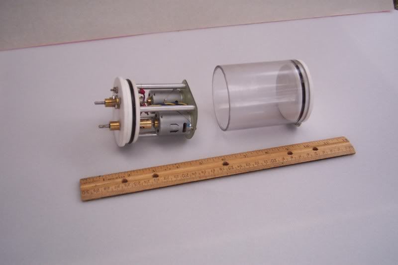
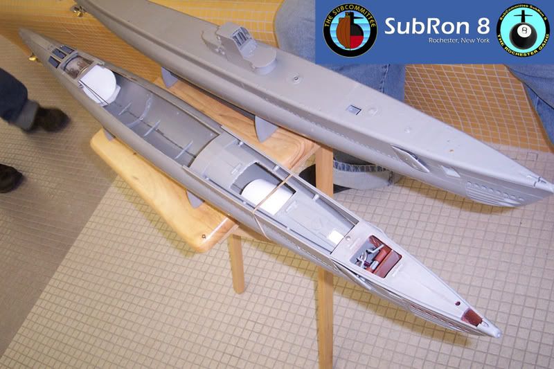
My approach to the hobby has been to use one single sealed container, containing all the expensive electronics and RCABS-R hardware, and move it from boat to boat. The propulsion unit, bladder and pressure vessel are all tuned to each specific hull, and remain with that boat. So my goal here was to cram my 19 x 3 inch cylinder into the Gato’s hull, along with all the additional parts to make it run. Even with a hull some 52 inches long, this was not quite so straight forward as it seemed, due to the way Revell set up the kit. Space is at a premium.
I broke the job down like this (not necessarily in this order):
1. Start with the rudder and stern planes, get them to pivot properly, set up the linkages.
2. Set up the prop shafts, stuffing boxes and bearings.
3. Build a unit which contains the motors.
4. Work out a scheme for the bow planes and retracts.
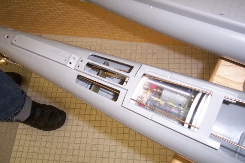
5. Make the hull cutouts necessary to install and maintain everything.
6. Install everything in the hull.
7. Test the assembled hull during sea trials.
8. Finish off the decks and conning tower.
9. Detail and paint the boat.
Since I don’t have 10 hours a day to devote to the project, like some people I know, this thread may take a while to complete. But I do hope, with luck, to do preliminary sea trials tonight, when Subron 8 makes our monthly winter excursion to the pool at the local YMCA.
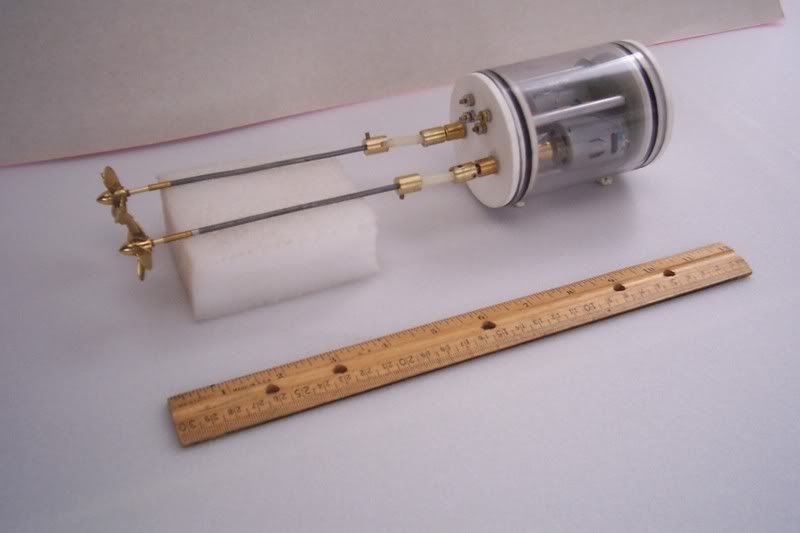
As I did not initially have the hull available at the time, I started with the drive assembly, which I did have all the parts for. It uses two motors from Small World Models in a direct drive setup. I used a 1/72 scale blowup of a Gato line drawing to plan the installation. Because the drawing did not have cross sectional views of the hull, there was some risk in this approach, and it came back to bite me later. When I installed the unit it sat 1/4 inch higher than planned due to the narrowing of the hull in this area. So the prop shafts did not align with the motor shafts. 1/4 inch is too much to compensate for with the short dogbone couplers, so I had to tilt the whole motor assembly up at the front end. This made the shaft offset much more reasonable. I may rework the drive unit later to lower the motors. We'll see.
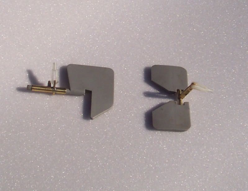
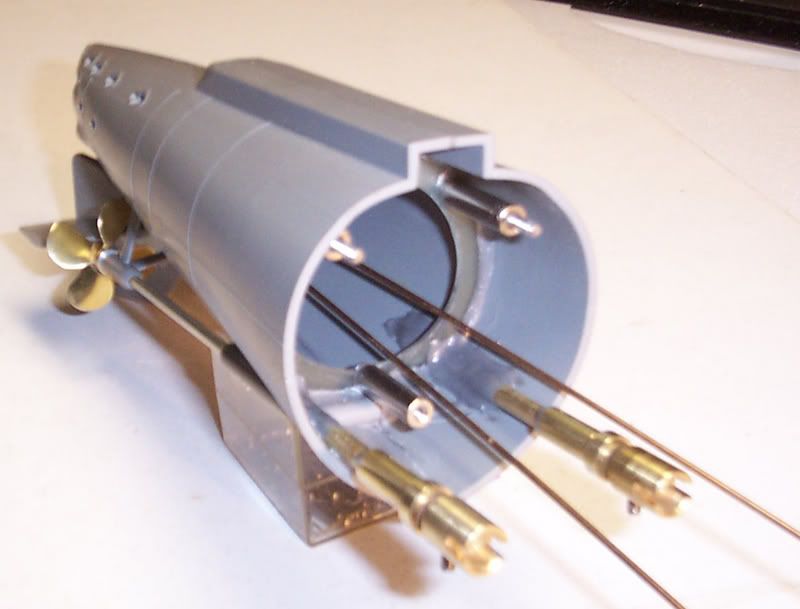
The rudder post is beefed up with a length of brass tubing after removing the two horizontal support tabs. A small brass arm is soldered to the tube for the control rod before sliding on to the rudder. A set screw locks it in place. The stern planes are drilled out to accept a 3/32 inch brass rod, which is epoxied in place. Short lengths of 1/8 tubing are put on either side of the control arm to act as bearings. These are clamped down by the lower half of the skeg.
Rudder, stern planes and prop shaft stuffing tube are shown in place. Two short pieces of brass tubing are glued to the hull section to act as upper and lower rudder post bearings. Hey… what are those two big tubes doing up at the top? Hmm…..
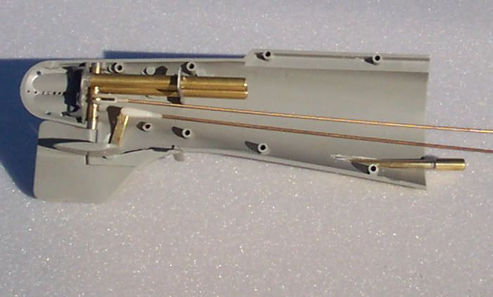
BigDave, notice that I managed to install the rudder with the torpedo door bulkhead in place and still get a plus and minus forty degree rudder swing.

The finished tail assembly. The expanded inboard ends of the stuffing tubes each contain a rulon bearing. The outboard end is too small to install one, so a short length of 1/8 ID copper tubing serves the purpose here, and in the drilled out strut assembly as well. BigDave gave me this idea. Most of the length of the stuffing tube is two sizes up from the shaft diameter, so the shaft contacts only the bearings at each end. The outside pieces of the stuffing tubes are not from the kit. I found it too difficult to hollow them out properly, so I made new ones from ¼ inch styrene tubing.

Three standoffs bolt the tail assembly to the hull to allow easy removal in case I need to access the linkages later. The bow section will be similarly bolted on.
The bottom view shows two small screws holding the lower half of the skeg in place so it can be easily removed for maintenance.

More to follow.
My approach to the hobby has been to use one single sealed container, containing all the expensive electronics and RCABS-R hardware, and move it from boat to boat. The propulsion unit, bladder and pressure vessel are all tuned to each specific hull, and remain with that boat. So my goal here was to cram my 19 x 3 inch cylinder into the Gato’s hull, along with all the additional parts to make it run. Even with a hull some 52 inches long, this was not quite so straight forward as it seemed, due to the way Revell set up the kit. Space is at a premium.
I broke the job down like this (not necessarily in this order):
1. Start with the rudder and stern planes, get them to pivot properly, set up the linkages.
2. Set up the prop shafts, stuffing boxes and bearings.
3. Build a unit which contains the motors.
4. Work out a scheme for the bow planes and retracts.
5. Make the hull cutouts necessary to install and maintain everything.
6. Install everything in the hull.
7. Test the assembled hull during sea trials.
8. Finish off the decks and conning tower.
9. Detail and paint the boat.
Since I don’t have 10 hours a day to devote to the project, like some people I know, this thread may take a while to complete. But I do hope, with luck, to do preliminary sea trials tonight, when Subron 8 makes our monthly winter excursion to the pool at the local YMCA.
As I did not initially have the hull available at the time, I started with the drive assembly, which I did have all the parts for. It uses two motors from Small World Models in a direct drive setup. I used a 1/72 scale blowup of a Gato line drawing to plan the installation. Because the drawing did not have cross sectional views of the hull, there was some risk in this approach, and it came back to bite me later. When I installed the unit it sat 1/4 inch higher than planned due to the narrowing of the hull in this area. So the prop shafts did not align with the motor shafts. 1/4 inch is too much to compensate for with the short dogbone couplers, so I had to tilt the whole motor assembly up at the front end. This made the shaft offset much more reasonable. I may rework the drive unit later to lower the motors. We'll see.
The rudder post is beefed up with a length of brass tubing after removing the two horizontal support tabs. A small brass arm is soldered to the tube for the control rod before sliding on to the rudder. A set screw locks it in place. The stern planes are drilled out to accept a 3/32 inch brass rod, which is epoxied in place. Short lengths of 1/8 tubing are put on either side of the control arm to act as bearings. These are clamped down by the lower half of the skeg.
Rudder, stern planes and prop shaft stuffing tube are shown in place. Two short pieces of brass tubing are glued to the hull section to act as upper and lower rudder post bearings. Hey… what are those two big tubes doing up at the top? Hmm…..
BigDave, notice that I managed to install the rudder with the torpedo door bulkhead in place and still get a plus and minus forty degree rudder swing.
The finished tail assembly. The expanded inboard ends of the stuffing tubes each contain a rulon bearing. The outboard end is too small to install one, so a short length of 1/8 ID copper tubing serves the purpose here, and in the drilled out strut assembly as well. BigDave gave me this idea. Most of the length of the stuffing tube is two sizes up from the shaft diameter, so the shaft contacts only the bearings at each end. The outside pieces of the stuffing tubes are not from the kit. I found it too difficult to hollow them out properly, so I made new ones from ¼ inch styrene tubing.
Three standoffs bolt the tail assembly to the hull to allow easy removal in case I need to access the linkages later. The bow section will be similarly bolted on.
The bottom view shows two small screws holding the lower half of the skeg in place so it can be easily removed for maintenance.
More to follow.


Comment