USS Greenling (SSN-614) Scratchbuild

Collapse
X
 
  • Time
  • Show
Clear All
new posts
  • rdutnell
    Junior Member
    • Nov 2012
    • 388

    #196
    Re: USS Greenling (SSN-614) Scratchbuild

    You are right Tom.

    The part was printed on a very expensive Rapid Prototype machine, specifically a ProJet 3500HD Max, that will do 16 micron layers.

    You might have missed it, but I have worked a deal with Pavel of Admiralty Model Works. I’m doing CAD work for him in exchange for printing. That is why I haven’t made any progress on Batfish. I’ve been working on items for him for the very purpose you stated, making master models to make molds for resin casting.

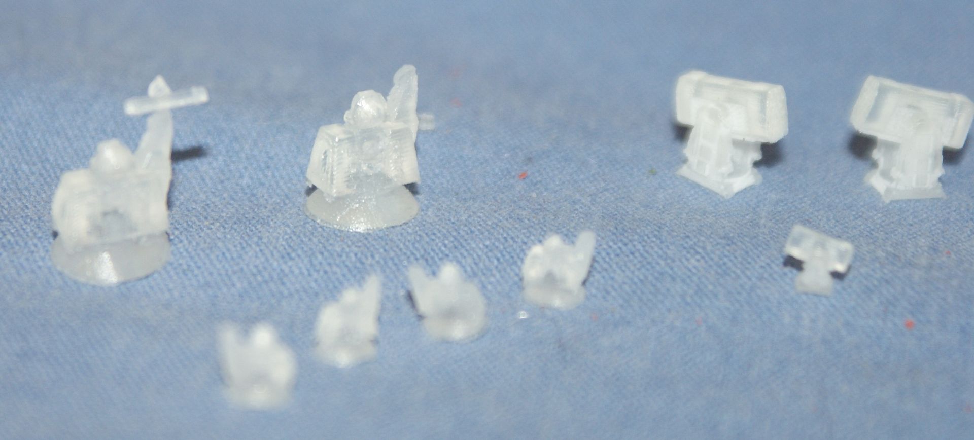
    I have already completed a RAM launcher, a Goalkeeper CIWS, a WW-II era moto-tug and a WW-II era Tilly crane, all to be made in 1/350 and 1/700 scales. The RAMS came out good. The Goalkeepers needed a redesign. I haven’t seen the WW-II parts yet. Here’s a picture of them as I received them.


    And here are a few pictures of them after I shot them with really bad primer.


    Currently, I am working on a 1/350 scale USCGC Bertholf model that has been a lot of fun so far. I am keeping a post…

    http://www.shipmodels.info/mws_forum/vi ... 7&t=152833

    …But I must admit I miss you guys. I became spoiled by all of your feedback. I’m not getting much on Bertholf.

    As for durability, we’ll find out. I have designed, and Pavel has printed a couple of test pieces to test different size protrusions, indentions, fillets, chamfers, rods and beams. I believe they have been mailed, so I should get them in the next day or two. The snorkel inductor, periscopes and antenna were pretty small though, and they survived me assembling them. I guess we will learn together.

    CHEERS!!!

    Comment

    • salmon
      Treasurer
      • Jul 2011
      • 2342

      #197
      Re: USS Greenling (SSN-614) Scratchbuild

      I am having a love/hate relationship with 3D technologies, but I believe it will only get better and better for the consumer. I remember when inkjet printers first became a consumer item. Available at commercial house originally to today, a color Laser Printer can be had for about $400. So, as time goes on, the 3D market will get better and our uses will become more creative.

      I must say, the hull detail on your bow section surprised me.

      Keep up the good work!
      If you can cut, drill, saw, hit things and swear a lot, you're well on the way to building a working model sub.

      Comment

      • scott t
        Member
        • Feb 2003
        • 880

        #198
        Re: USS Greenling (SSN-614) Scratchbuild

        Now I have to keep up with another website. Thanks, Russ
        Your Coast Guard Cutter is looking pretty cool.

        Scott T

        Comment

        • tom dougherty
          Senior Member
          • Jul 2005
          • 1361

          #199
          Re: USS Greenling (SSN-614) Scratchbuild

          that will do 16 micron layers
          Just to calibrate people, 16 microns is about 8 bacteria laid end to end (E. coli is roughly 2 microns long). Another way to state it is that 1millimeter has 1000 microns in it. So the step size here is 0.016 millimeters. Very, very fine indeed, and it explains the great detail seen. Home printers in the $1200 range have a minimum layer of around 200 micron, or about 12 times coarser than the above. BTW, the cartridges for the home printer run about $49 a piece. The ProJet 3500HD Max is $69,000 and roughly the size of a refrigerator. see]http://www.3dsystems.com/3d-printers/professional/projet-3500-hdmax#.UedBs4vD-M8[/url]

          Yes, prices will come down with time, but quality 3D printing is still some way off, and the Cost of Goods (plastic material) may stay high (Just like printer ink cartridges).

          I just knew that Ph.D. in microbiology would come in handy some day on this board!

          Comment

          • rdutnell
            Junior Member
            • Nov 2012
            • 388

            #200
            Re: USS Greenling (SSN-614) Scratchbuild

            UPDATE 85

            Hi guys,

            It’s good to hear from everybody. Tom, I have found computers in general to be a love/hate relationship. They have opened uncountable doors, but they have also added burdens in our lives we didn’t use to have. And they are great when they work, but they have also provided me with a lot of aggravation that I could have done without.

            I thin 3D printers will follow more the path of large scale plotters than of printers. Everybody prints text so printers were sure to be a big hit. A lot of people print color pictures, so color printers were also sure to be a big hit. Not as many need large scale printers, but enough do, so that they are in practically every print shop, and in specialty offices like engineers and architects. 3D printers are in the same boat. The difference between 3D printers and plotters is that a real market could be developed for 3D printers. That isn’t the case for plotters.

            But when I was punching computer punch cards to do a simple pipe flow velocity profile in the early 80’s, the thought of an I-phone was pure science fiction. I never would have thought that they would really exist. So who knows.

            In any case, I still think this link is to the most creative use I have seen for 3D printing.

            http://www.google.com/imgres?imgurl=htt ... BA&dur=152

            Sorry to do it to you Scott!

            As you can tell, I’m having a lot of fun with it, except that, as I said in my last post, I’m not getting the excellent feedback like you guys on this site have provided. I even e-mailed the Bertholf site and have yet to hear anything. Maybe CG’ers like to keep things close to the vest.
            Anyway, I think you will like my next project for Pavel, when I finish Bertholf, too. (Not that I’m going to finish anytime soon).


            And Tom D, what can I say? You’ve schooled me on submarines and on modeling. It only seems appropriate that you school me in microbiology too. Perhaps I should start reporting my dimensions in e coli.

            Anyway, in my last post I mentioned that I mentioned I was expecting some test pieces, well they arrived today. The image below is a Legend for the part, showing the sizes of the various features I wanted to test.


            Pavel printed the piece using two different materials, one marked XHD (Extra High Density?), the other marked UHD (Ultra High Density?)
            Here’s the XHD piece as I received it…


            …And here’s the piece marked UHD.


            As you can see, the XHD came out better than the UHD. Here are some more pictures of the XHD as I received it.


            I sprayed them both with primer after I took these pictures. Here’s what the pieces looked like with one coat of Tamiya (poorly spraying) primer on them. I only took one picture of the UHD, because the quality is poor compared to the XHD. It looks though like something got out of alignment in printing, and the poor quality might not have anything to do with the material, but the way it is the XHD is superior so all but the second photo below are of the XHD piece.


            Note][/url]
             
            The smallest 0.25” tall post in the foreground of the next two pictures has a radius of 0.003” (that's 38 e-coli ), same with the holes.


            Summary

            Etched lines into the surface - Extruded circles (cylinders) do a better job than extruded rectangles (skinny blocks). The 0.004” etched lines didn’t print at all. From 0.005” up did great.

            Raised lines on the surface - As with the etched lines, the 0.004” raised lines didn’t print. Above 0.005”, both extruded circles (cylinders) and extruded rectangles (skinny blocks) worked well so either one could be used effectively.

            Surface depressions (for PE placement, female connections or effect) – Only the largest circles even show up at 0.003” depth, and only marginally better at 0.005”. Circles with a radius of 0.0075” or larger etched in 0.0075” or more came out good. Surprisingly, all sizes drilled through nicely, but they look cleaner from 0.0075” radius and up.

            Surface projections (male connections, posts, or for effect) – As with surface depressions, only the largest circles show up at 0.003” depth, and they are only marginally better at 0.005”, although in some cases 0.005” protrusions for larger objects would be useful. All protrusions from 0.0075” an up came out nicely. Another surprise to me was that all of the 0.25” protrusions printed nicely, including the 0.003” radius. Even more surprisingly, I flicked it with my finger a few times and it didn’t break. Then I grabbed a paint brush and pretended to paint it and it handled that fine too. It flexed, but didn’t break.

            So, 0.0075” (95 e-coli ) seems like the magic number. This corresponds to 2.6” at 1/350 scale and 5.3” at 1/700 scale. Any depression larger than that and protruding or etched into the surface by that amount or more, will work fine. Smaller sizes can be used, but care is needed when using them. At the extreme 0.003” isn’t good for much, and yet small 0.003” (~1” at 1/350 scale, ~2” at 1/700 Scale) holes or 0.003” posts could be made.

            The second test piece is really 2 pieces, to test various connection types that I have been using without really knowing if they will work or not. I’ll post pix when I get them.

            Now for the update portion of this update, which isn’t much. My buddy texted me that the base is completed. I haven’t seen it yet and don’t know when I get it, but you know I will post pictures when I get it. There isn’t much hurry though because I talked to Sherry at the family (the patriarch was one of my football coaches in high school) owned trophy shop that is making my plaques, and they are all taking a family trip in the form of a week-long Alaskan cruise, and she didn’t know if she would finish before she leaves. I told her not to worry about it and have fun, and that I was jealous, so I expect I won’t see them until the first of August. I guess that is a good thing. The sooner I finish the model the sooner I have to face parting with it.

            A more significant Update will follow shortly.

            CHEERS!!!

            Comment

            • rdutnell
              Junior Member
              • Nov 2012
              • 388

              #201
              Re: USS Greenling (SSN-614) Scratchbuild

              UPDATE 86

              I'm double posting tonight because a few days ago I received a suggestion that, if I separated the blades from the hub of the screw, I might be able to orient the blades in a more suitable position for printing that could possibly eliminate the feathering seen in the screws my friend printed for me. Of course, it might not be necessary, because I think that Pavel’s printer is somewhat better than my buddy’s, but since I don’t know what type of printer my buddy has it is just speculation. In any case, I decided to try it, I just never posted it. So here it is...

              To begin, I took the original screw…


              …Subtracted the hub…


              …Then separated the blades and deleted all but one of them.


              Then I redrew the hub…


              …And copied the hub and blade to the side.


              Ithen prepared to add a tab to the base of the blade by extruding a properly placed and oriented rectangle…


              …Which I joined to the blade.


              I then did a polar array to evenly space the 7 blades around the hub.


              Next, I turned the hub layer back on, and subtracted the blades from it…


              …And drilled out the shaft hole.


              Here is an image of the blade. If it is printed upright, it may print better. We may find out.


              While I was making changes to the screw, and since I had the blades separated, I decided that I might as well make one with thicker blades in case the feathering persists, so I took a blade (before the attachment tab was added to it and copied it over half a blade width, thus increasing the width 50%.


              I then repeated the previous steps to make a new screw.


              Although I don't show it, I copied the completed screw to the side and joined the blades to the hub, so that I now have 4 versions of the screw, the original, the original sliced, and the thicker screw both as one part and separated. I have sent them to Pavel (as I have all of the parts now) telling him that my order of preference is 1) the original, 2) the sliced original, 3) the thicker bladed screw as one part, and 4) the separated thicker screw. If the original prints out nicely none of the others will ever be printed. If it doesn’t I asked him to work his way down the list until one does. Of course, if worse comes to worse, I can always work one over like I did for the first model, but it would be cool if I could print a nice one out.

              The last time I talked to Pavel, he said that he was going to start printing the sub parts, so I will let you know when I start receiving them.

              CHEERS!!!

              Comment

              • rdutnell
                Junior Member
                • Nov 2012
                • 388

                #202
                Re: USS Greenling (SSN-614) Scratchbuild

                UPDATE 87

                Good Morning Guys!

                Greenling had a baby Thresher.


                I had the OKB Grigorov 1/700 Scale USS Thresher (SSN-593) kit that I bought back when I first thought of building Greenling for my buddy, and decided I would put it together. I will post more pictures when I finish it.

                CHEERS!!!

                Comment

                • rdutnell
                  Junior Member
                  • Nov 2012
                  • 388

                  #203
                  Re: USS Greenling (SSN-614) Scratchbuild

                  UPDATE 88 – 7/30/2013

                  HI Guys!

                  I finally connected with my friend that made the base for me, and he completed it. I picked it up yesterday.


                  He didn’t finish it, which I didn’t expect him to, but he recommended that I use Sanding Sealer and Lacquer, so I went to Sherwin Williams and bought both in spray cans. Here’s what it looked like after sanding and two coats of sanding sealer, with more sanding between coats and after the last one.


                  This was followed by 4 coats of lacquer, again sanding between coats.


                  If you were wondering, the wood is African Mahogany, which as you can see is a beautiful wood. It still needs probably 2 more coats of lacquer, which will have to wait until this weekend when I get back home, as I am on another sampling run in eastern Oklahoma. The original plan was to layer the inside with felt to protect the model, but the wood is so pretty I may just use a few strips instead of covering the whole interior, but we shall see. Also, I know this isn’t the kind of base typically used for submarine models, but as I have said before, I want this first generation model to be accessible for handling. The 2nd generation model will have pedestals, for which you may recall, I have included mounting points for in the model.

                  CHEERS!!!

                  Comment

                  • rdutnell
                    Junior Member
                    • Nov 2012
                    • 388

                    #204
                    Re: USS Greenling (SSN-614) Scratchbuild

                    UPDATE 89

                    Hello Everybody!

                    The base is essentially completed except for the plaques. I decided not to put the felt over the entire surface and instead did three 1-1/4” strips. The felt that I could find was only 1/16” thick, so I doubled up, using a total of six strips.


                    There are still a couple of scratches that I am going to try to fix, but it may not be doable without major work, in which case, I will leave it. Greenling is going to cover it up anyway.


                    Perhaps the base is a bit of an over kill, but I think that when the plaques are on it, it will look good. In any case, the folks from Sooner Trophies are back, and I have been in contact with them. I should have the plaques sometime next week.

                    CHEERS!!!

                    Comment

                    • salmon
                      Treasurer
                      • Jul 2011
                      • 2342

                      #205
                      Re: USS Greenling (SSN-614) Scratchbuild

                      If I may make a small suggestion, trim back the strips from the edges so the do not show while the sub is on the stand. It looks too good to have those showing. IMHO
                      If you can cut, drill, saw, hit things and swear a lot, you're well on the way to building a working model sub.

                      Comment

                      • rdutnell
                        Junior Member
                        • Nov 2012
                        • 388

                        #206
                        Re: USS Greenling (SSN-614) Scratchbuild

                        Small suggestions, big suggestions, “that is just flat out stupid” suggestions are all welcome Tom and I appreciate your frankness. I’m not sure that your suggestion on trimming the edges is going to be necessary though. I mean, I like the ship and I like the base, but I’m not crazy about the ship in the base. I think my wife is right when she says that, although the base is really pretty, it doesn’t highlight the model. So, I am considering redesigning a base more along the lines of what Tom D suggested a month ago. In fact, I probably should follow the advice Tom D gave regarding redoing the decals, “We know how this is going to end. You will agonize for a while, and then fix it. The important point will be to have a strategy to fix it with minimal effort and damage.” The only reason I haven’t already started is because this is the 1st generation model and I can get it right on the next one, chalking this one up to experience. In any case, I am going to wait until the plaques arrive before I change it. If I decide to keep it, I’ll consider trimming the strips as you suggested Tom.

                        Sorry, what is IMHO?

                        Comment

                        • salmon
                          Treasurer
                          • Jul 2011
                          • 2342

                          #207
                          Re: USS Greenling (SSN-614) Scratchbuild

                          In My Humble Opinion - IMHO
                          Wives can sometimes see things we guys just miss. Alright, I will standby an watch my friend.
                          Peace,
                          Tom
                          If you can cut, drill, saw, hit things and swear a lot, you're well on the way to building a working model sub.

                          Comment

                          • scott t
                            Member
                            • Feb 2003
                            • 880

                            #208
                            Re: USS Greenling (SSN-614) Scratchbuild

                            Looks to me like you have a very handsome work stand there.

                            Scott T

                            Comment

                            • rdutnell
                              Junior Member
                              • Nov 2012
                              • 388

                              #209
                              Re: USS Greenling (SSN-614) Scratchbuild

                              UPDATE 90

                              Good one Scott! It would indeed be a handsome work stand. But I don’t know if it is going to be around that long.

                              The image below shows part of the problem. On the left is my final design. On the right is the “workstand”. No wonder I thought it looked like overkill.


                              But even if it wasn’t too big, the recess is the same size as I designed, and part of the problem is that the ship sits too far down into the stand. As my wife so bluntly put it, “It looks sunk.” Well! Perhaps not sunk but temporarily grounded.

                              So I decided to see how I could modify it to make it better. I was thinking I could start by slicing off the cradle 1/8” below the low point.


                              Then slice the long faces at 30 degrees for mounting the plaques.


                              I would put a small chamfer on the other faces...


                              …Then put the plaques on the new base.


                              So, then I had this idea that I could make my own pedestals and 3-D print them. I extruded a 1” diameter circle up 1¾” Subtracted a revolved ¼” diameter circle near the bottom, added a revolved ½” circle in the middle than added a revolved polyline to blend it to the top. I used the bottom section of the base to design the platforms that I blended into the body using lofted polylines.


                              I drilled out ½” diameter holes through them and cut out bolt head recesses.


                              I also drilled ½” holes through the base and a 1” diameter hole ½” into the bottom.


                              I was feeling good about them.


                              Then I created an STL file of the part and uploaded it to Shapeways, and my parade got thoroughly rained on. To print one in “White Strong & Flexible” would cost almost $50. To print one in “Gold Plated Glossy” would cost over $380. So back to the drawing board (or computer screen).

                              Using the cradle, I could slice some blocks...


                              …And add some of the blocks to the base.


                              Or perhaps I could slice the cradle into pieces…


                              ..And use them instead of the flat blocks.


                              I also spent a couple of hours yesterday looking around town for something I could use to make pedestals. Having no luck, I turned to the Internet and ordered a couple of “Brass Pedestals for Model Ships”. Unfortunately, there are no dimensions provided so I won’t know if they will work until later in the week, when I receive them.


                              After ordering these I stumbled on some advice that suggests using brass lamp risers. I know of a local store in town that probably has these, but they won’t be open until tomorrow. In the meantime I think I’ll check to see if Lowe’s has any. If all else fails I could order some on line.


                              I think my preferred option is the cradled slats, but it involves a lot of cutting. If I use the pedestals or risers I think I would have to bolt the ship to them, something I didn’t want to do and would require drilling a hole in the hull something I really don’t want to do. I’ll keep you posted on what I do, and as always, all comments and suggestions are welcome. Perhaps I will listen. If I had listened to Tom D a month ago I wouldn’t be in this mess.

                              CHEERS!!!

                              Comment

                              • scott t
                                Member
                                • Feb 2003
                                • 880

                                #210
                                Re: USS Greenling (SSN-614) Scratchbuild

                                Good moringin Russ,
                                I like this design best, but you have some great ideas.
                                Also I have heard it said less is more. So simple brass rod standoffs could be a way to go.

                                Scott T

                                Comment

                                Working...