My Rescue Barge

Collapse
X
 
  • Time
  • Show
Clear All
new posts
  • Ralph --- SSBN 598
    Junior Member
    • Oct 2012
    • 1417

    #151
    March 20th ================================================

    Last start in the shop.
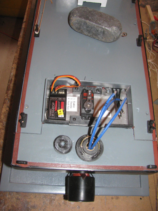
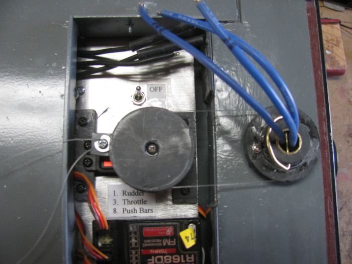
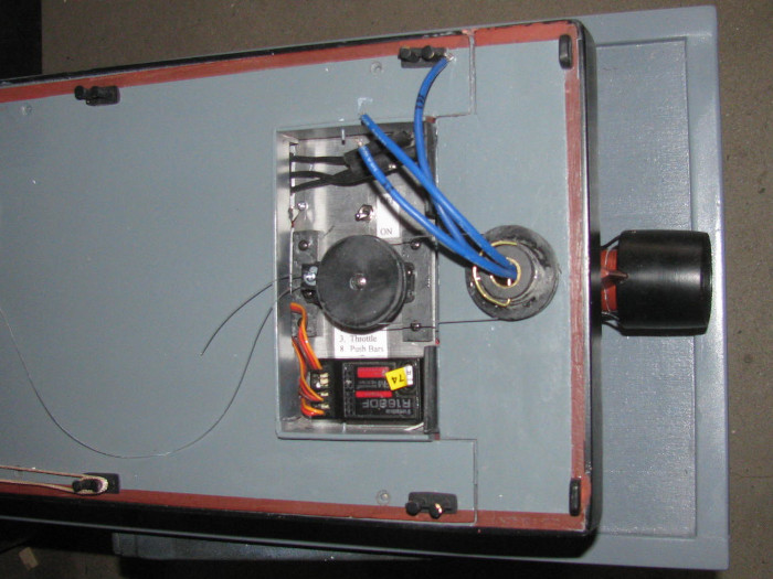
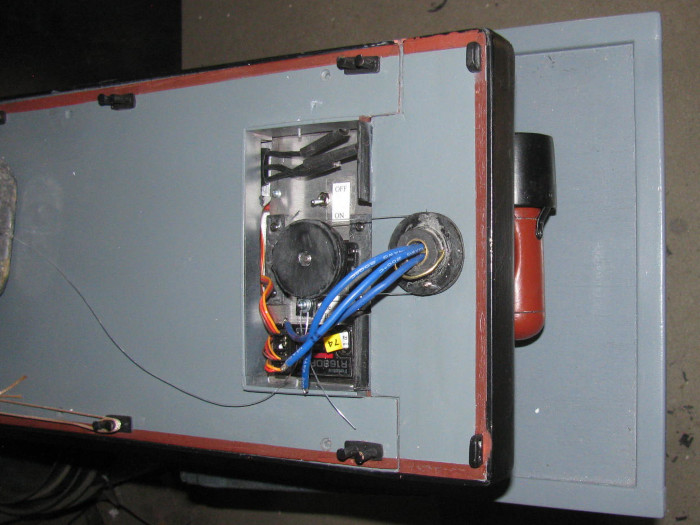
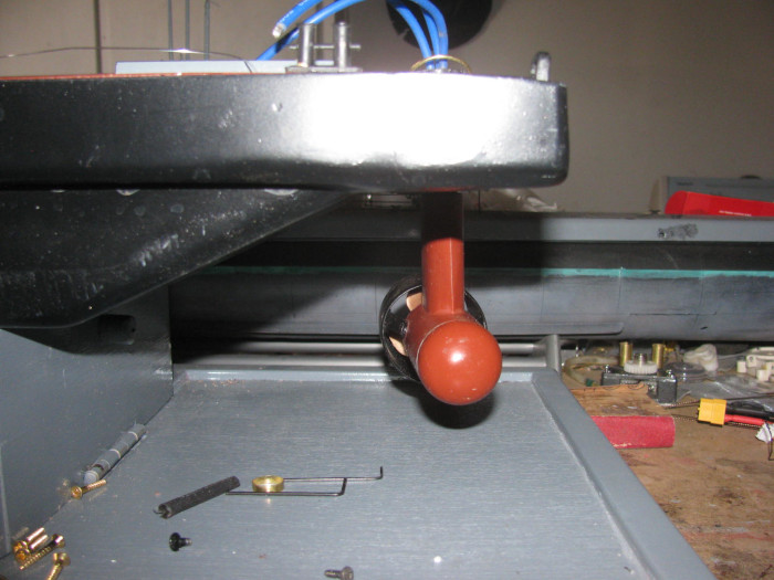
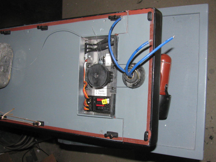
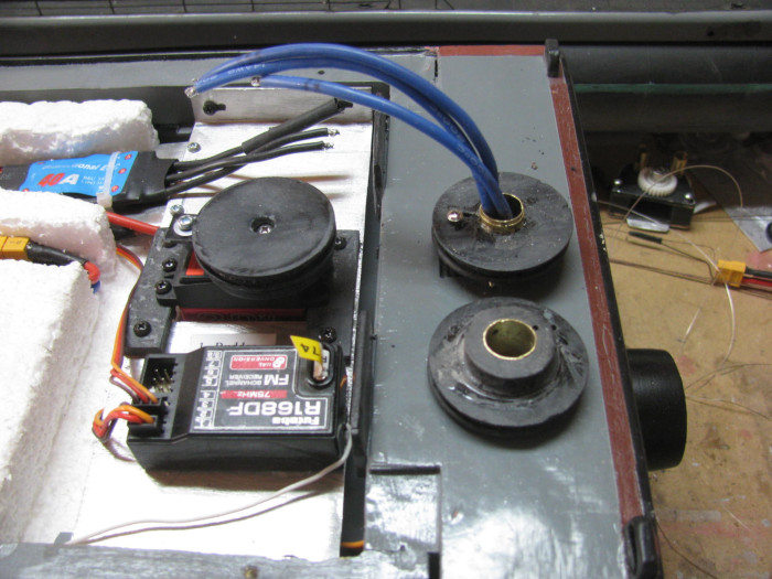
    Put the planned steering system on the rudder post and servo.
    It works for about 4 minutes.
    Then the line used was cut and failed.
    Tried it again making sure not to cut the line.
    Again the line cut.
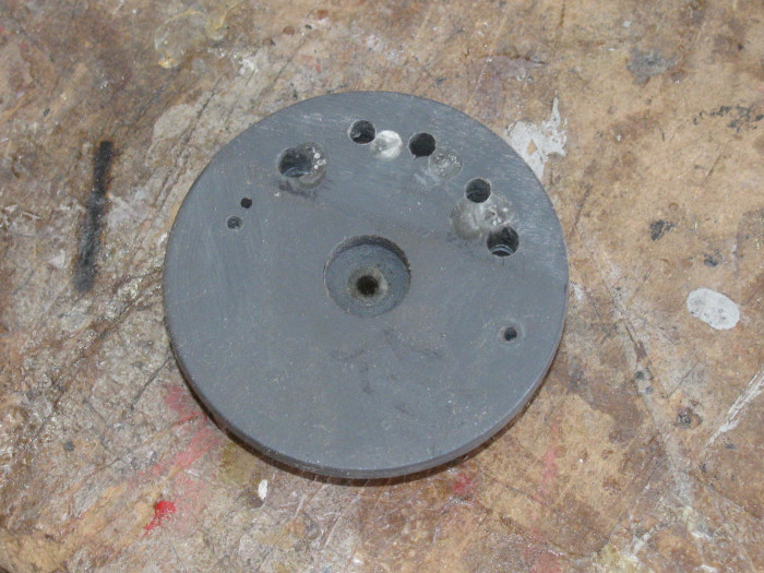
    It appears to be the clamp I made to hold the 2 end of the line.

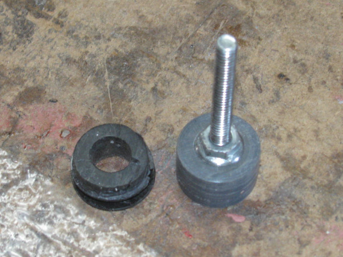
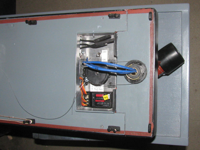
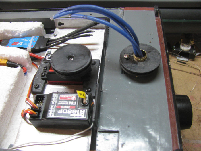
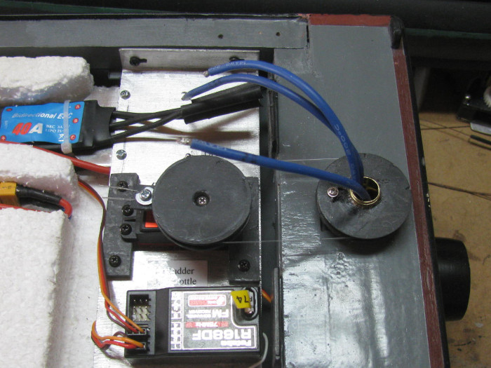
    Okay, I will try an o-ring.
    My o-ring was a little short but I could stretch it to go over the two pulleys.
    This did not work.
    The o-ring slips.

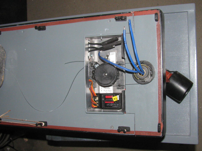
    Okay, tomorrow I will go back to the cable instead of the 20 pound line.

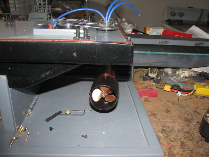
    As a last resort, I can use brass rod linkage and not have the 180 degree turning of the motor pod.
    -----------------------------
    I may make a paper drawing of the steering post and servo.
    I can draw a 3/4" and 1" pulley over the centers and see how long a gear belt would be.
    Convert it all to metric and then maybe I can find a belt and gear drive that might work.
    ==================
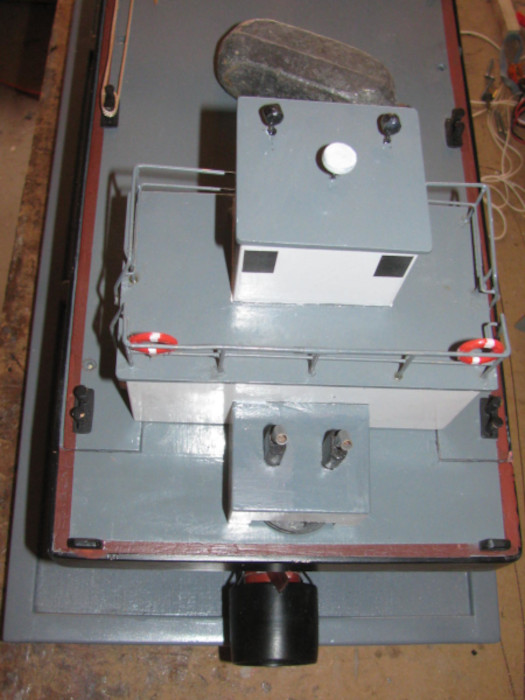
    Tomorrow if I can not get the cable to work, I will make up the brass rod linkage parts so at least I h ave a working boat.

    Comment

    • scott t
      Member
      • Feb 2003
      • 880

      #152
      How about something like a dryer belt tensioner pulley. Spring loaded.
      Click image for larger version

Name:	Capture.JPG
Views:	1
Size:	21.0 KB
ID:	135812

      Comment

      • Ralph --- SSBN 598
        Junior Member
        • Oct 2012
        • 1417

        #153
        Thanks, Scott.
        All suggestions help me figure out a way to make it all work.

        I didn't spend much time looking at the o-ring failure but after thinking about it, it might be that the o-ring was too tight and binding the rudder post in the through tube.
        I did notice that the o-ring would stretch on the pull side before the rudder would turn with a jump.

        I got to this late in the day and I probably should have just waited.

        So tomorrow, I will start fresh and early.

        Another idea came up from a prototype Gato gear box sitting on the shelf in the office.
        If I can find some of the gears that made it to the parts box and see if they will span the gap from rudder post to servo. (2 11/16" center to center)

        I didn't plan the rudder system until after I made the stern block extension.

        I may look in to moving the rudder post forward and cutting the back end off the tail block.
        I can not move the servo back because it is touching the hull rise.

        The barge went together so quickly at first and then this issue with steering, only because I want the 180 degrees. (90 by 90)
        If I would settle for the 120 degrees (60 by 60) push rods would solve the problem in a matter of minutes.

        Yea, I plan to fight for the 180 degrees.
        I like the idea.

        Comment

        • greg w
          SubCommittee Member
          • Mar 2010
          • 360

          #154
          On my barge I was able to use a servo pulley that was salvaged from an old sailplane. It has a small spool to allow for adjusting tension I also went as far as to put an anchoring screw in the rudder post and recessed it to not interfere with the lines crossing the pulley I used leftover sailboat rigging line and it has been good for several years now
          Click image for larger version

Name:	barge steering.jpg
Views:	1
Size:	10.7 KB
ID:	135813

          Comment

          • Ralph --- SSBN 598
            Junior Member
            • Oct 2012
            • 1417

            #155
            Greg, looking at your drawing, this is exactly what I thought would work.

            The issues in not the system but the cable I am using.
            It is fishing wire leader and it does not bend around corners very well.
            I needed to pull a lot of tension.
            Going around the 1" pulley I have on the rudder post was not easy.

            I also anchored the cable on the rudder post pulley and then again on the servo pulley.
            This morning, I had it all assembled and working.

            After about 5 minutes, I started seeing slack in the cables.
            My servo pulley had started coming apart.

            My pulleys are made from plastic sheet (1/16") glued together to build up to about 3/8" thick.
            It appears the cable got in between 2 layers and cut though the joint.

            What are you using for the cable/line between the pulleys? (belt?)
            Maybe that would help.

            I am now looking through the tool shed to see if I can find a couple of blocks of aluminum (I know I do not have brass blocks) I can make new pulleys out of.
            I do have blocks of gray PVC plastic I could use.

            Something else I found while digging in boxes.
            I found several different size nylon gears from old cars.
            I found 3 that would span the distance.
            Only there are 2 big and 1 small.
            I would have to cut a notch in the back of the engine cover for the gear to run.
            If I can find another small gear, that would work.

            I would like to find two 1" diameter and one 1 7/8" diameter.

            There is a RC indoor track about 35 miles away that is open on Tuesdays. about noon.
            Maybe I need to go for a drive.

            Comment

            • greg w
              SubCommittee Member
              • Mar 2010
              • 360

              #156
              you could put a series of screws in the pulley near the edges to keep the pieces from separating. A piece of wood would also work for the pulley. My "cable was some leftover sailboat rigging but I would think any small nylon line would work. I didn't use gears due to a fear of keeping alignments and making things more complicated. Greg

              Comment

              • Ralph --- SSBN 598
                Junior Member
                • Oct 2012
                • 1417

                #157
                ===============
                I went back out to the shop.
                I dug through old rejected end caps.
                Found one that had enough center to make a clean pulley.
                This was an end cap that was used in the Skipjack 3.5" cylinder.
                I need a clean 1" disk.


                Out to the tool shed and made it happen.
                Here is the disk still on the 1/4" bolt I use as a spindle.
                I need to measure where the groove should be to line up with the servo pulley.
                Before cutting the groove, I will turn the servo disk so I can fit them and line up the grooves.
                On the left is the original pulley with groove and and upper ledge with holes for brass rod clip


                The PVC cuts really easily. (soft)
                I may still look for aluminum to make these pulleys.

                Comment

                • Ralph --- SSBN 598
                  Junior Member
                  • Oct 2012
                  • 1417

                  #158
                  Greg, about using screws.
                  I think it is easier to make a new pulley from a solid piece instead of laminating several pieces of 1/16" plastic together.

                  It was the top 1/16" flange piece that cut off.

                  Comment

                  • Ralph --- SSBN 598
                    Junior Member
                    • Oct 2012
                    • 1417

                    #159
                    March 22nd ================================================

                    This morning, I cut and turned 8 disks to make new pulleys.

                    Before making the disks, I measured the room under the deck cabin.
                    Looks like I may have to cut a slot at the back of the engine cover.
                    I am making the pulleys bigger in diameter.
                    The servo pulley will be 1/4" bigger in diameter and the rudder post pulley will be 1/2 bigger in diameter.
                    Both pulleys are now the same size.

                    Drilled the center holes.
                    Some where 1/4", one was 5/16"+ and some where 9/16"
                    Depending on whether they go on the rudder post or the steering servo.

                    After drilling the disks, I stacked them keeping the correct holes together so I could put a steel shaft through the holes to keep the disks straight with each other.
                    Both pulleys are in vises to keep pressure on the plastic while the bonding cement does what it does.

                    After it all cures completely, I will test fit in place and make sure to get the two pulleys on the same level plane.

                    Looking over the original pulleys, I found that the disks where the cable cut through had not been put under pressure in the vise.
                    This left a small gap the cable found and cut through.

                    Yesterday when I posted the failure, Greg suggested putting screws through the disks near the edge to give them more strength.
                    Greg, I will be at the hardware store tomorrow and I will be getting small screws and most likely small bolts to go through the disks.
                    It is a simple addition that will keep the disks from separating.

                    Comment

                    • Ralph --- SSBN 598
                      Junior Member
                      • Oct 2012
                      • 1417

                      #160
                      I finished the rudder post pulley.
                      The pulley is the bottom and there is a top that is to give more bearing surface.
                      I put a brass tube inside to join the two parts.
                      Glues them and pinned them.
                      Drilled the brass keeper pin holes through the brass tube using the holes in the top piece as my guide.

                      The 2 pieces where glued together yesterday and clamped over night in the small table vise.

                      In the photo the new pulley is on the rudder post and the old smaller part is there for size comparison.
                      I did not take the photo at the right angle to show the screw in the pulley to hold the steering line.
                      I did test it for strength and I could not pull the line through when the screw was tightened. (moderately)

                      The photo on the right shows the pulley sticking out the back of the deck house after I cut the slot.
                      I will make a cover later after I get everything working.
                      Probably make it look like steps to get on to the engine cover.
                      ...

                      The servo pulley was made yesterday but not jointed to the bottom piece that connects the pulley to the servo.
                      The small vise was being used.
                      The pulley and the base are now in the vise under pressure to cure.

                      Work will continue on Thursday.
                      Tomorrow is VA surgery day.
                      I have 2 appointments with 2 different surgeons.
                      This is an on going never ending thing.

                      Spent most my life outside working and playing.
                      Now I pay.

                      Comment

                      • Ralph --- SSBN 598
                        Junior Member
                        • Oct 2012
                        • 1417

                        #161
                        March 24th ================================================

                        Home from VA by 2pm.
                        All good.
                        The first surgeon did several cuts on my wrist and arms.
                        Second surgeon looked at what he did 3 weeks ago and said I didn't need to come back unless something goes wrong.

                        Came home, had lunch and out to the shop.

                        Started by finishing the servo pulley that was in the vise from yesterday.
                        Mounted the pulley on the servo and started putting the line that will work the rudder.
                        Here it is installed.
                        The line has not been trimmed yet.


                        Time to test the system.
                        Lots of photos coming.
                        First three are with the Tx control set at 100% on servo rotation.

                        Tx control centered.


                        Control stick, full right.


                        Control stick, full left.


                        While I had the system running, I opened the Tx menu and reset the servo from 100% to 135% by watching the rudder turn.
                        It now turns just past 90 degrees.

                        No need for center, so here I have
                        Control stick, full right at 135%.


                        Control stick , full left at 135%.


                        I now have what I wanted all along.
                        Trim the line and check line retaining screws snug.
                        Put the deck house on and I think I am done.

                        There is more touch up painting but I can live without doing that.
                        It's a working barge.

                        Oh. . . Thought I would try the phone video again.

                        Rudder testing video.
                        Last edited by Ralph --- SSBN 598; 03-24-2021, 09:54 PM.

                        Comment

                        • Ralph --- SSBN 598
                          Junior Member
                          • Oct 2012
                          • 1417

                          #162
                          March 25th ================================================

                          Yep! the barge is done.
                          That was yesterday.

                          Today, I was in the shop making a modification. (of course I was)

                          Looking at the barge and the photo, I do not like the alignment of the two pulleys.
                          The rudder post pulley is lower than the servo pulley.
                          It all works fine but I see the line dragging on the pulley edge on both pulleys.

                          I do not want to be running and have the steering line cut and loose control.

                          Turning the rudder post pulley over, the alignment is almost straight in line. (less than a 1/32")
                          I tried to figure a way to make the original pulley work but there are so many holes from rerouting the line that there is not much plastic left to work with.
                          Thought about cutting the pulley off the hub but that was more work than making a new pulley assembly.

                          So, I did. I cut plastic squares and then turned them in to disks. (2 sizes as needed)

                          This afternoon, I have been glue the disks together on a 1/4" shaft to keep the disks centers straight.
                          Just glues the hub to the pulley disks.
                          In the vise under a lot of pressure.

                          I cut a short brass tube to go over the rudder post that will be glued in the pulley assembly.
                          The short brass tube has been installed in to the pulley hub.
                          Once cured, I can drill the 1/16" hole through the hub for the brass pin that will hold the pulley on the rudder post.

                          I will have to be careful drilling the holes through because the motor wires are already in the post.
                          My plan is to put a piece of smaller tubing down through the post with the wires going through the smaller tube.
                          The smaller tube should stop the drill bit from getting to the wires.
                          I will drill from both sides.

                          Tomorrow there will be drilling.
                          Last edited by Ralph --- SSBN 598; 03-25-2021, 08:12 PM.

                          Comment

                          • Ralph --- SSBN 598
                            Junior Member
                            • Oct 2012
                            • 1417

                            #163
                            March 26th ================================================

                            Here are both the original and new rudder post pulleys.
                            Basically they are the same except the new one has the pulley groove near the top and the original has the groove near the bottom.
                            The pulley with the groove near the top puts the steering line in a more straight line pull.
                            The original pulled down enough to rub on the pulley edge.

                            The small screw is to capture the steering line so it does not slip during operations.
                            There is a screw at the front of the servo pulley that captures the steering line ends and allows me to put tension on the line so there is no slack.


                            The pulley installed.
                            There is a brass 1/16" rod going through the pulley and the brass steering tube post.
                            You can see just the very end of it.
                            There are modified wheel collars on each end to hold it in place.
                            I sanded both sided of both wheel collars flat so they would go under the pulley and not drag on the deck.


                            In this photo the steering line has been installed.
                            Checked for pod centered on hull and tensioned.

                            Only need to solder the 3 speed controller wires to the motor wires.


                            After finishing the steering system, I got out my paint bushed and started doing the touch up painting.
                            Spots like on the hull edge behind the pulley.
                            On the upper corner and other places around the hull.

                            Tomorrow my plan is to solder the wires.

                            Once that is done, I think I am going to call this Rescue Barge build, COMPLETE!
                            Barge will go in to it's transportation box and wait until I can schedule a day at the lake. (soon, I hope)

                            Wait! Like always, there is one more thing.
                            I need to mount the weight in the bow to make the hull sit level in the water.
                            Right now it is just sitting under the foam and can slide about.

                            1 minute job. (drop of silicone glue and put weight in place. Then DONE.
                            ===================
                            Only thing I can think of are photos from running at the lake
                            Last edited by Ralph --- SSBN 598; 03-26-2021, 06:28 PM.

                            Comment

                            • Ralph --- SSBN 598
                              Junior Member
                              • Oct 2012
                              • 1417

                              #164
                              March 27th ================================================

                              The speed control to motor 3 wires are soldered and tested.
                              Motor runs in correct directions.

                              Built the small cover that will hide the edge of the rudder pulley.
                              Is attached to the deck house engine cover.

                              A bunch of small plastic pieces glued together and shaped.
                              It measures about 9/16" high by 5/16" deep by 1.5" wide.

                              This is currently clamped to the engine cover to cure.

                              Should be able to paint it tomorrow with a little touch up on the deck house.
                              ---------------------------
                              I have 3 deck lines I want to either coil or lay back and forth on the deck.
                              Glue them down so they do not fall off the deck in to the water and possible get caught in the propeller.
                              I have a test length to see how I will lay them.
                              Coiling does not seem likely.
                              When I tried to coil the test piece, it would not go tight enough to look right and as soon as I moved my fingers to get a better hold, it uncoiled faster than I could stop it.

                              Something to work on after painting.

                              Comment

                              • Ralph --- SSBN 598
                                Junior Member
                                • Oct 2012
                                • 1417

                                #165
                                March 28th ================================================

                                Out to the shop for some painting.
                                Masked off the deck house to paint the new step extension.
                                Well, then it turned on me.

                                What I thought was white paint was clean satin.
                                Looked all over and I have no white.

                                So painting is not going to happen today.

                                I did install 2 small magnets to pull the back of the deck house down to the deck.
                                I had a 1/8" gap.
                                Now it is gone.

                                Painting will have to wait until I get in to town for some white paint. (maybe tomorrow)

                                Going to put off trying to do the deck ropes.

                                Today has turned in to a day off from the barge.
                                -----------
                                Here is a photo from when I was building the deck house.


                                Here is the extension box over the steering pulley.
                                I needed just short of 1/4" more engine cover to get over the pulley.

                                Painted a primer coat.
                                Spray paint tomorrow.
                                Last edited by Ralph --- SSBN 598; 03-28-2021, 07:59 PM.

                                Comment

                                Working...
                                X