USS Nautilus - final Edition

Collapse
X
 
  • Time
  • Show
Clear All
new posts
  • drschmidt
    Member
    • Jul 2014
    • 424

    #31
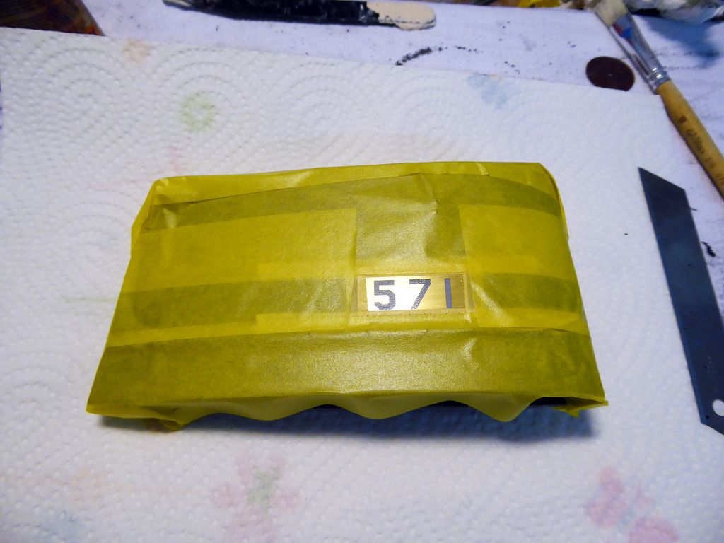
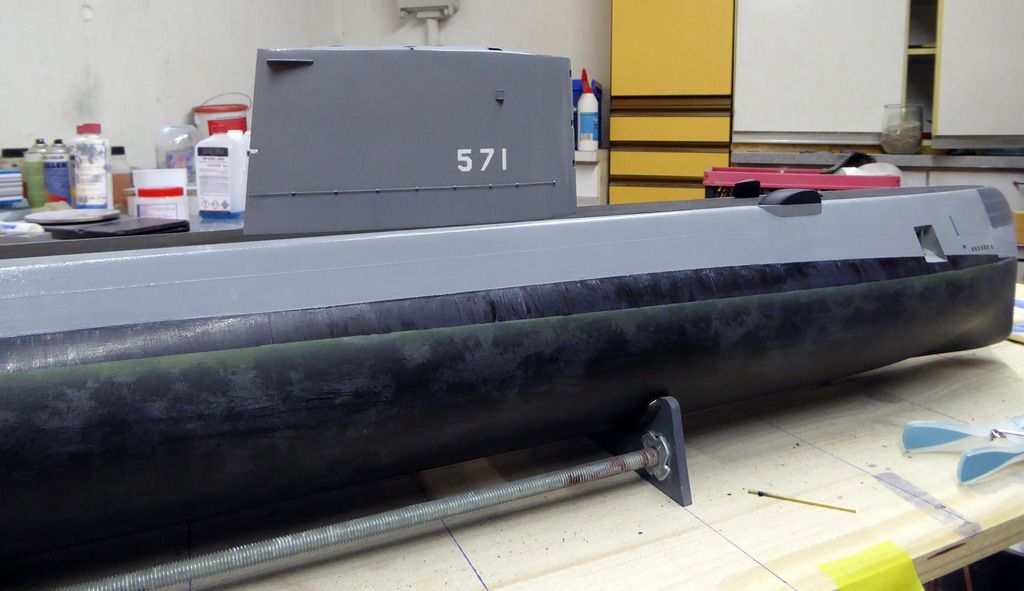
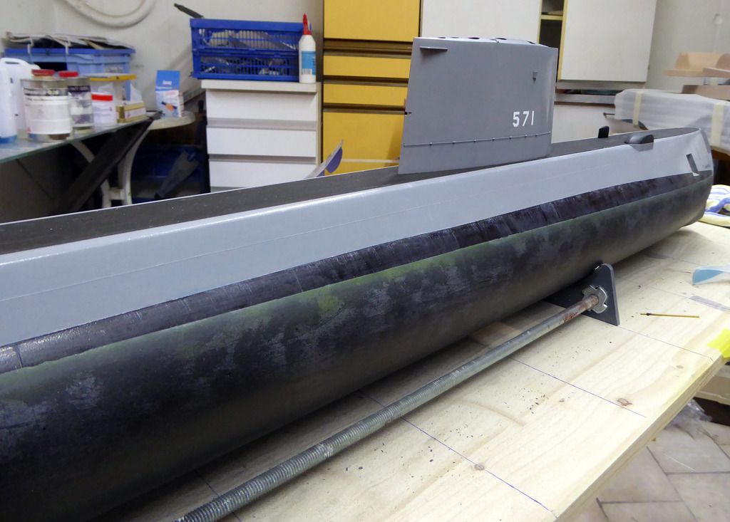
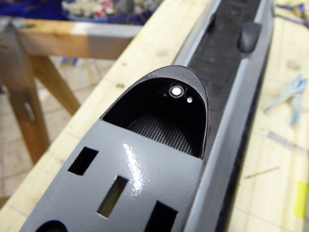
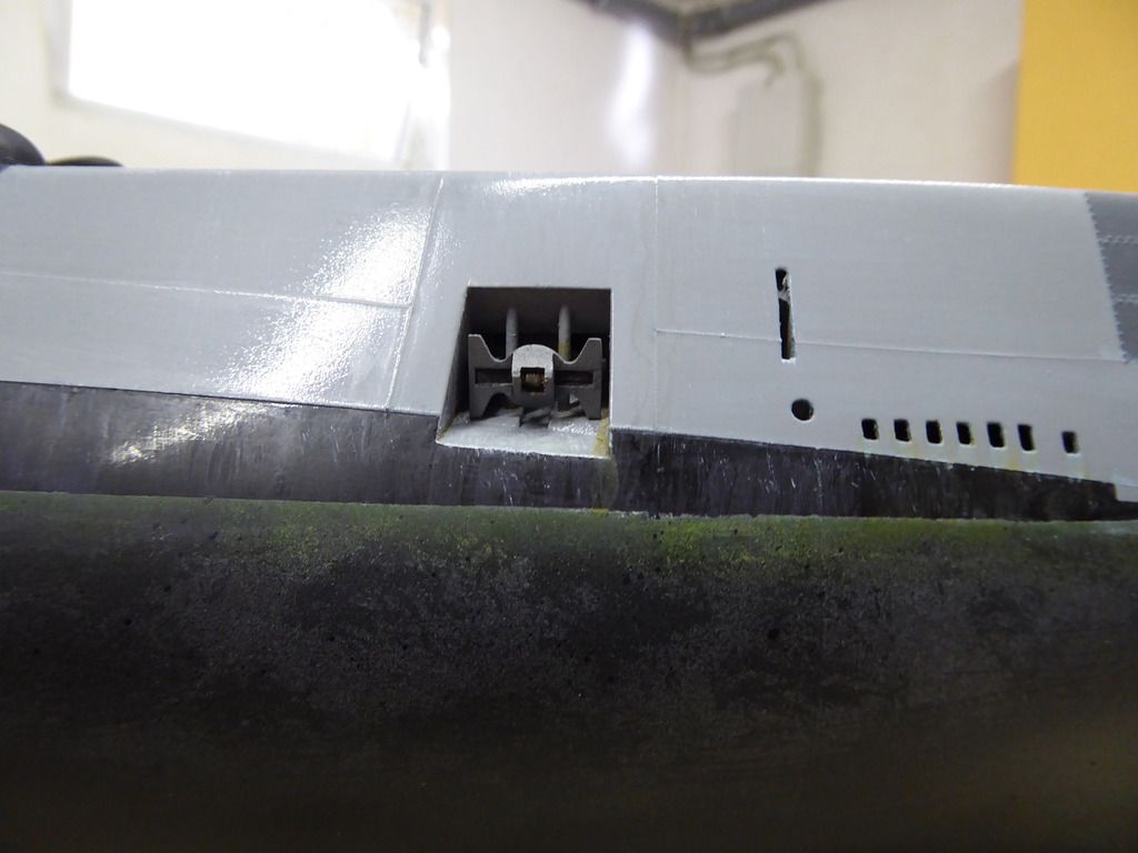
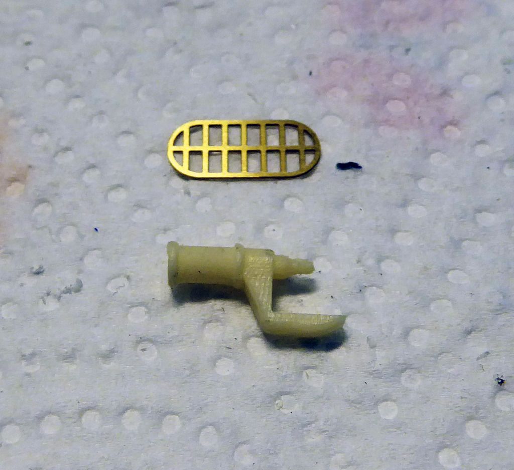
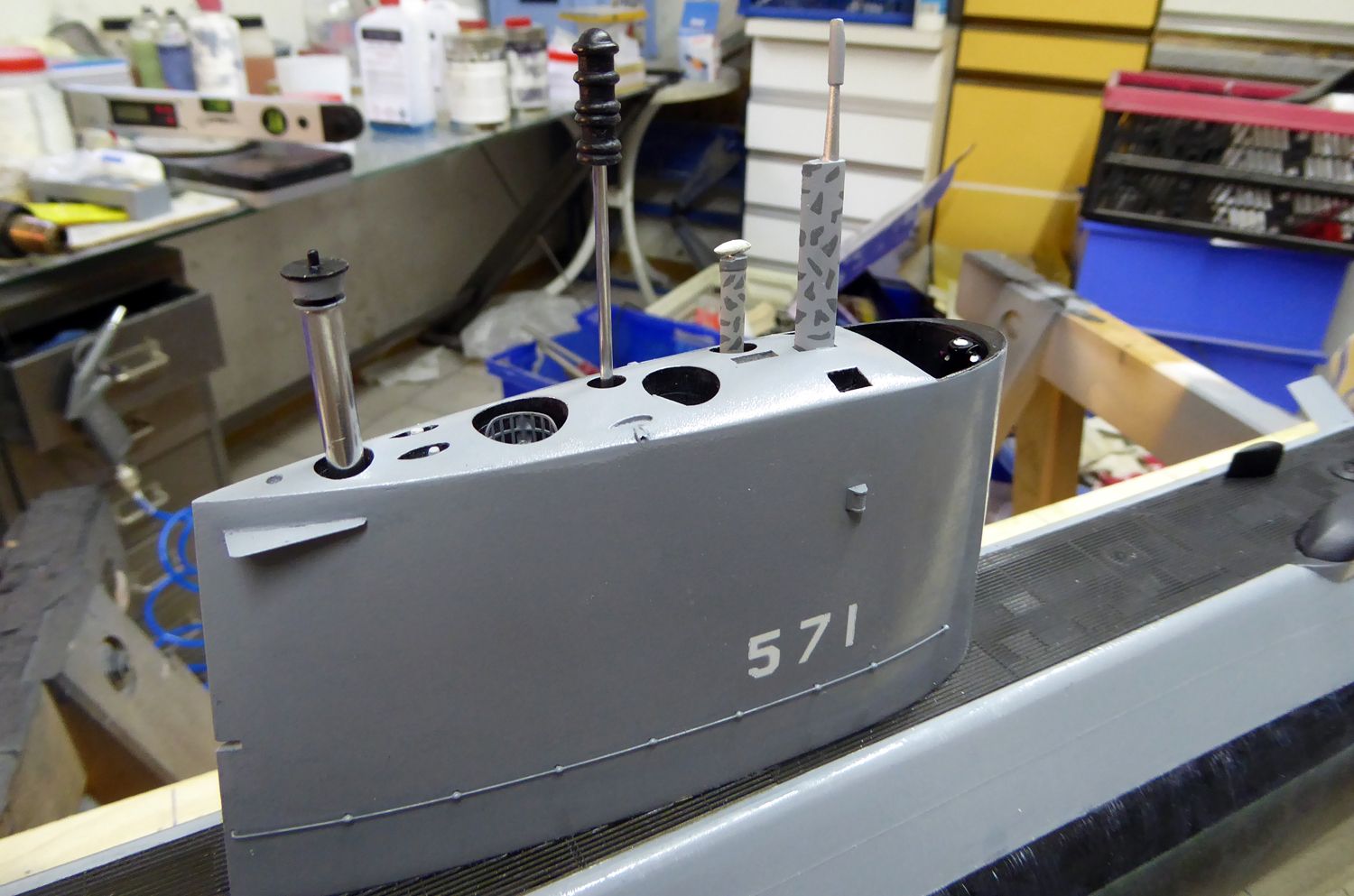
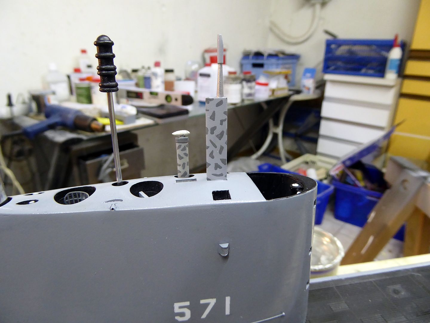
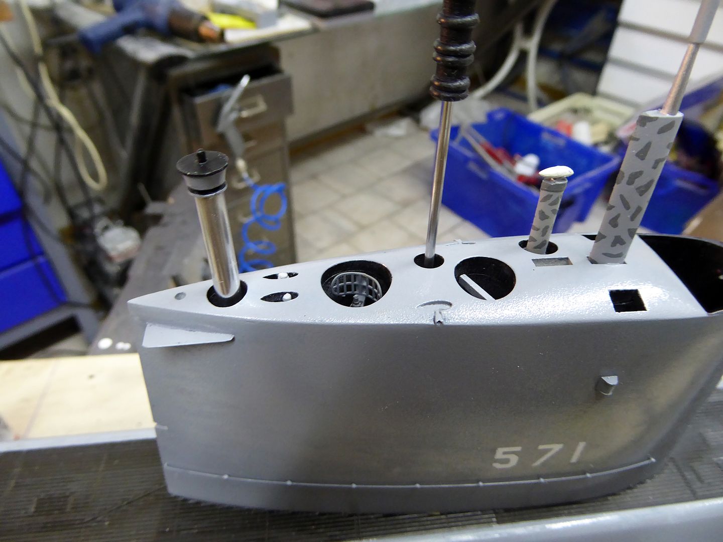
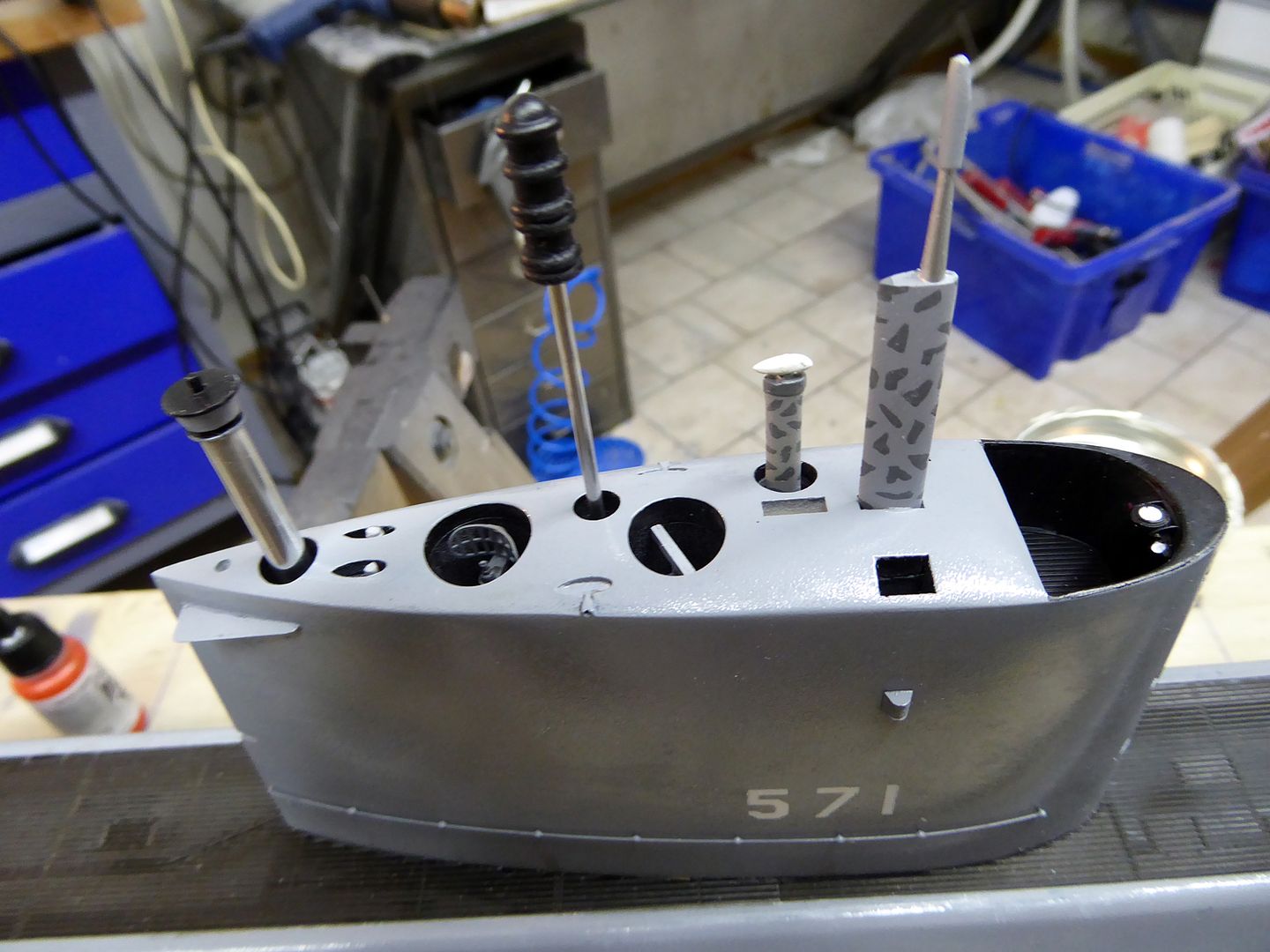
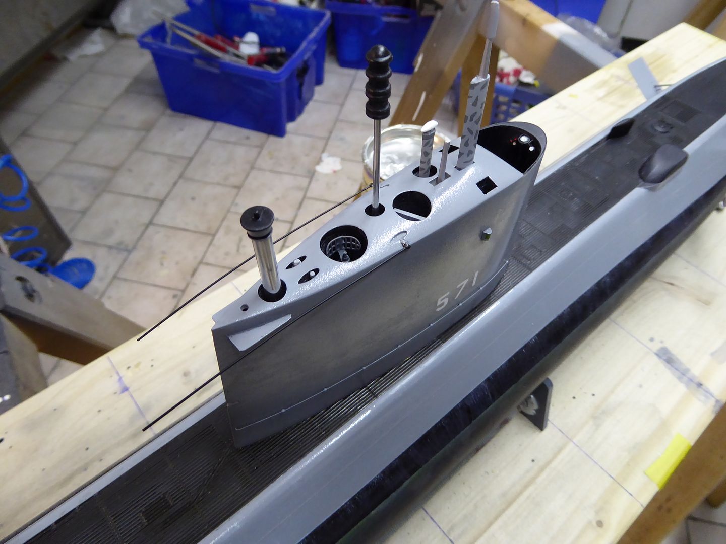
    On it goes with the aging of the base coors. I mainly use filters and washes by the company M.I.G.. A slow process where one applies alternate coats of ultra-thinned colors. The curing times between the cotes takes quite some time, but it’s worth the effort. In addition the ship numbers are airbrushed using the photo-etched stencil.


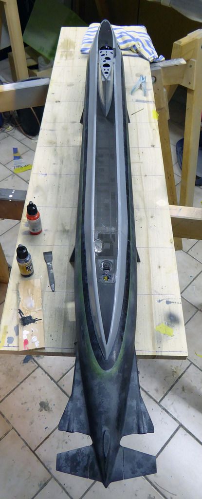
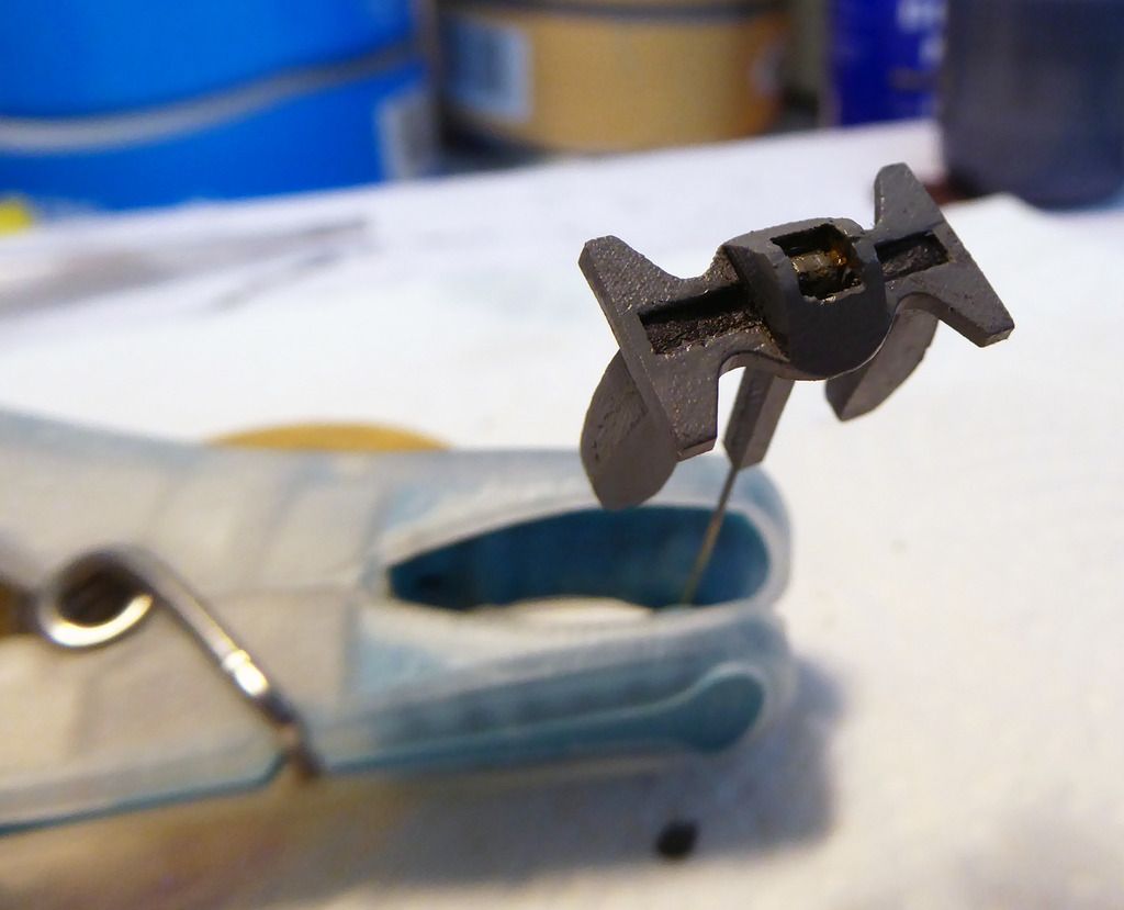
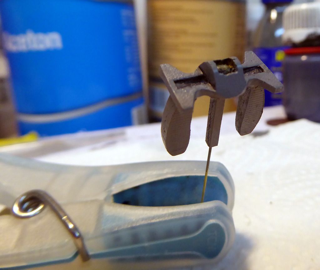
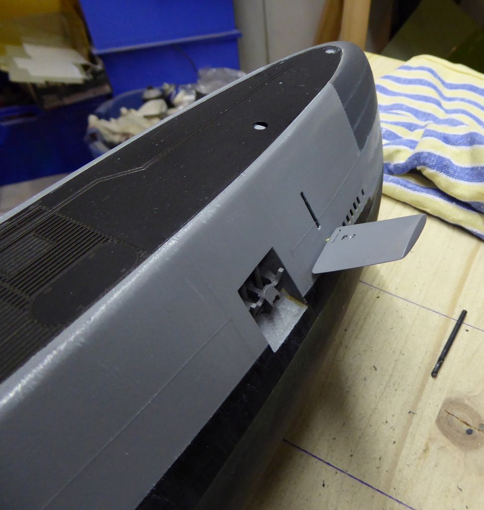
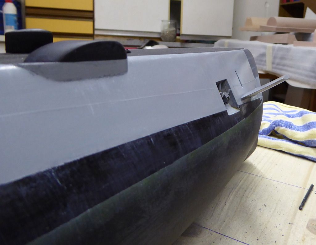
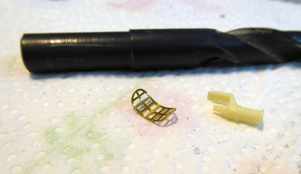
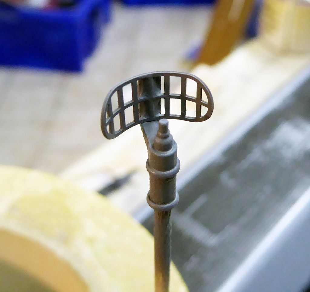
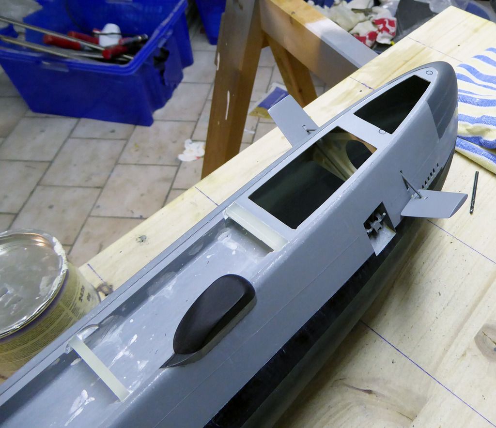
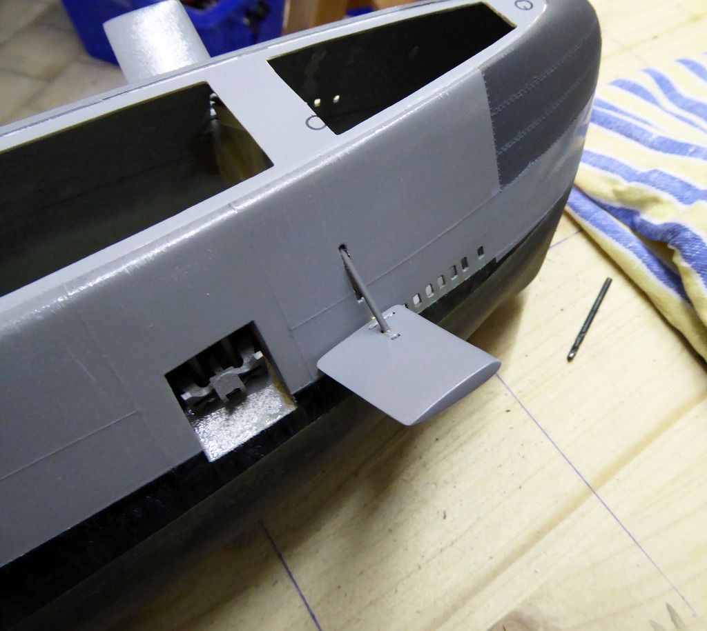
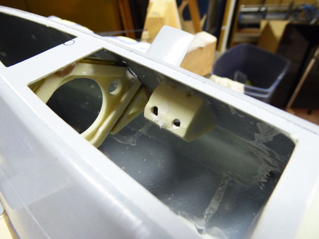
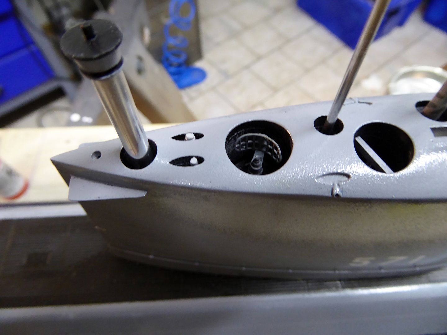
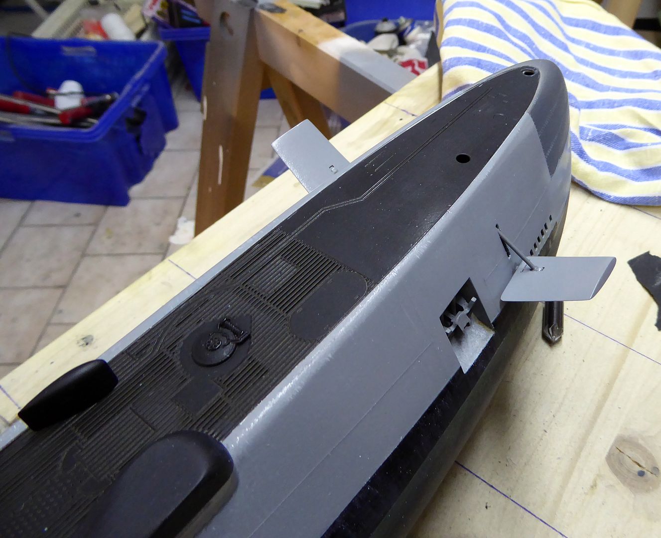
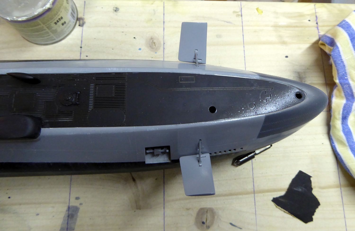
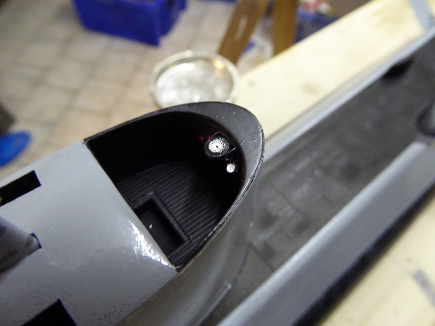
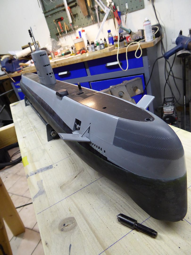
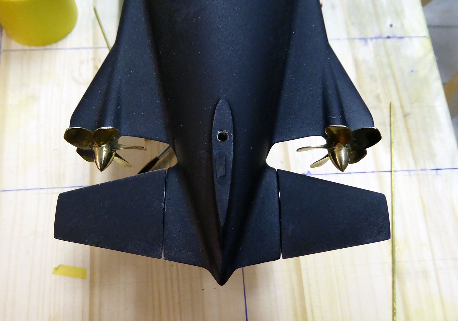
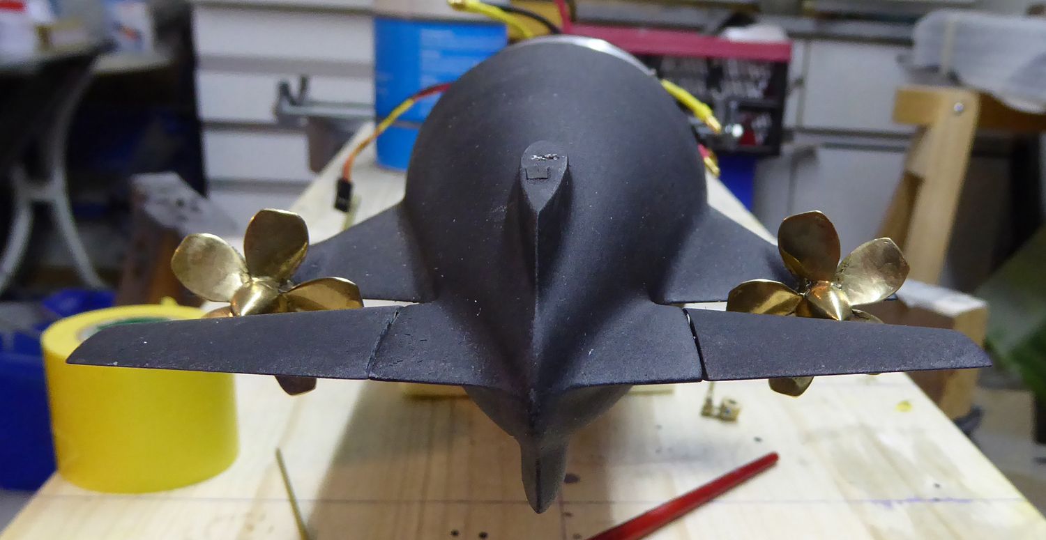
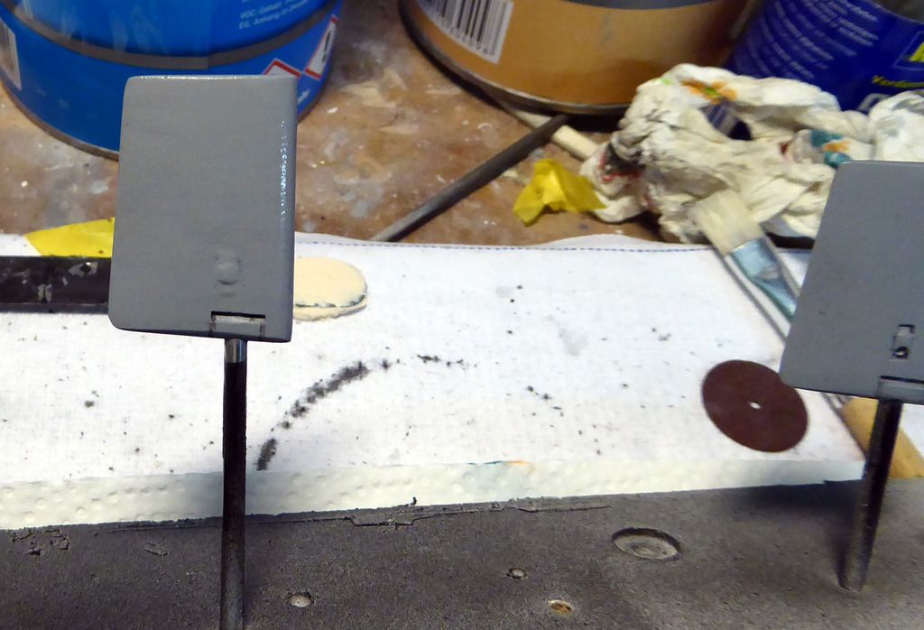
    The bridge and the bow planes are painted as well:


    Comment

    • drschmidt
      Member
      • Jul 2014
      • 424

      #32
      Anchor: Painted, grey filter, black wash, and a little bit of rust….and then test mounted:


      The bow planes in their places for the first time. One can nicely see the 60° tilt of the planes. Next they will be glued into place.


      Comment

      • drschmidt
        Member
        • Jul 2014
        • 424

        #33
        Assembly oft he radar mast from a PU resin part and a photo-etched part:


        The brass net is bend around a 10 mm diameter drill:


        Glue together and paint in the base color:


        The bow planes and the anchor are glued into their respective bulkheads:


        Comment

        • drschmidt
          Member
          • Jul 2014
          • 424

          #34
          Detail work on the sail: The mast are painted and glued in the desired position:


          The bow planes are finished as well:


          Comment

          • drschmidt
            Member
            • Jul 2014
            • 424

            #35
            Finally the whip antennas are installed on the sail. They are soldered together out of 0,5 mm diameter brass wire and 1 mm diameter brass studs. Paint them black and then glue them into the respective holes in the sail cap:


            The compass repeater gets a decal with the indicators.


            Next are the draft mark and then the boat is ready for getting its clear coat:

            Comment

            • drschmidt
              Member
              • Jul 2014
              • 424

              #36
              The painting and weathering of the boat is done and the final 2-component clear coat (matt) is applied. NO comes the fitting of the boat:

              Because of the limited space, the linkages are custom-made. A 3 mm brass tube is hammered even and a 2 mm diameter brass stud is soldered into it. A 3 mm brass set collar is soldered to a 2 mm thick brass linkage and we have it. Needed two times.


              The threads of the propeller shafts are shortened and the props are secured using Loctite blue. The prop shafts are put into the stern tubes using plenty of grease. Everything is secured using set collars.


              The watertight motor units are put into place and secured using M16 brass screws. Latter are locked with a second pair of nuts. Loose cardan joints transmit the torque and allow for thermal expansion:
              #


              The two servos are secured from below using 3 mm stainless steel screws:


              2 mm brass rods with clevises make the linkage:


              The feedthrough is sealed using Engels rubber bellows:


              Tight fit but doable:

              Comment

              • drschmidt
                Member
                • Jul 2014
                • 424

                #37
                To install the dive plane linkage one needs a very long Allen-wrench. Self-made using a 5 mm brass tube and hot glue.


                Thread the linkage onto the dive plane shaft, position it right and tighten the screw. This requires patience:


                The dive planes are glued onto the shaft. To adjust their distance to the hull, 0,2 mm precision stainless washers are used.


                The linkage to the servo shaft is done using a piece of 3 mm diameter brass tube and soldering:


                And this is how the thing works in real:

                Comment

                • drschmidt
                  Member
                  • Jul 2014
                  • 424

                  #38
                  The linkages to the control planes are done:


                  Next is the installation of the pressure switch, which is mounted in a bracket milled out of 5 mm PVC. It’s screwed into place using a M4 thread rod and a distance piece made out of 10 mm thick GRP sheet material:


                  Comment

                  • drschmidt
                    Member
                    • Jul 2014
                    • 424

                    #39
                    The 1,5 liter Engel piston tank gets a compact control unit with Hall sensor. To get it actuated in a reasonable time, I chose the 540 motor variant. For this combination, magnets have to be glued onto the main gear wheel. Due to their mutual attraction, gluing the 3 mm x 1mm cylinder magnets directly onto the wheel is rather tricky. That’s why I chose to fabricate a magnet wheel. The segments are laid down onto 1 mm styrene sheet material. 12 magnets will be used:


                    The magnet positions are drilled with a 3 mm drill bit. The central hole has 9 mm diameter.


                    On a plane plastic sheet treated with release wax the wheel is positioned and the magnets are glued into the respective holes.


                    Let cure…

                    Comment

                    • drschmidt
                      Member
                      • Jul 2014
                      • 424

                      #40
                      After the glue has cured clean the magnet disk from glue residues, cut it into two pieces and glue it onto the main gear of the piston tank. Then put the control unit onto the micro switches:


                      The 540-version of the piston tank has no fix point for the Hall sensor. Therefore one fabricates a L-bracket out of 1 mm brass sheet material:


                      The Hall sensor is screwed into place, a 3mm diameter hole is drilled into the micro-switch board of the piston tank and then the Hall sensor is installed so that the magnets pass closely to the sensor head when the gear turns:


                      Test fit everything in the inner structure:


                      Comment

                      • salmon
                        Treasurer
                        • Jul 2011
                        • 2342

                        #41
                        Having the additional magnets will allow you to do finer adjustments, right?
                        If you can cut, drill, saw, hit things and swear a lot, you're well on the way to building a working model sub.

                        Comment

                        • drschmidt
                          Member
                          • Jul 2014
                          • 424

                          #42
                          That's what I hope and the manual says. In the first version I had 6, now I went for 12.....more doesn't make much sense.

                          Comment

                          • Guest

                            #43
                            Is the board responsive enough to be accurate with that arrangement? Only the H-bridge is relay based, so purely start and stop with no PID. I'd have thought overshoot or undershoot was very easy with high encoder resolution.

                            Comment

                            • drschmidt
                              Member
                              • Jul 2014
                              • 424

                              #44
                              There are still micro-switches as end-stops.

                              Comment

                              • JWLaRue
                                Managing Editor, SubCommittee Report
                                • Aug 1994
                                • 4281

                                #45
                                I think the given the thread pitch of the jack screw that you may not see any difference.......

                                -Jeff
                                Rohr 1.....Los!

                                Comment

                                Working...