
After successful test runs with the prototype, I've decided to incorporate my experiences with it in a second, improve version of the Nautilus. This time it will reach its design waterline and will have a higher battery capacity. I start with a complete set of parts that would also make a kit (in case I do it):
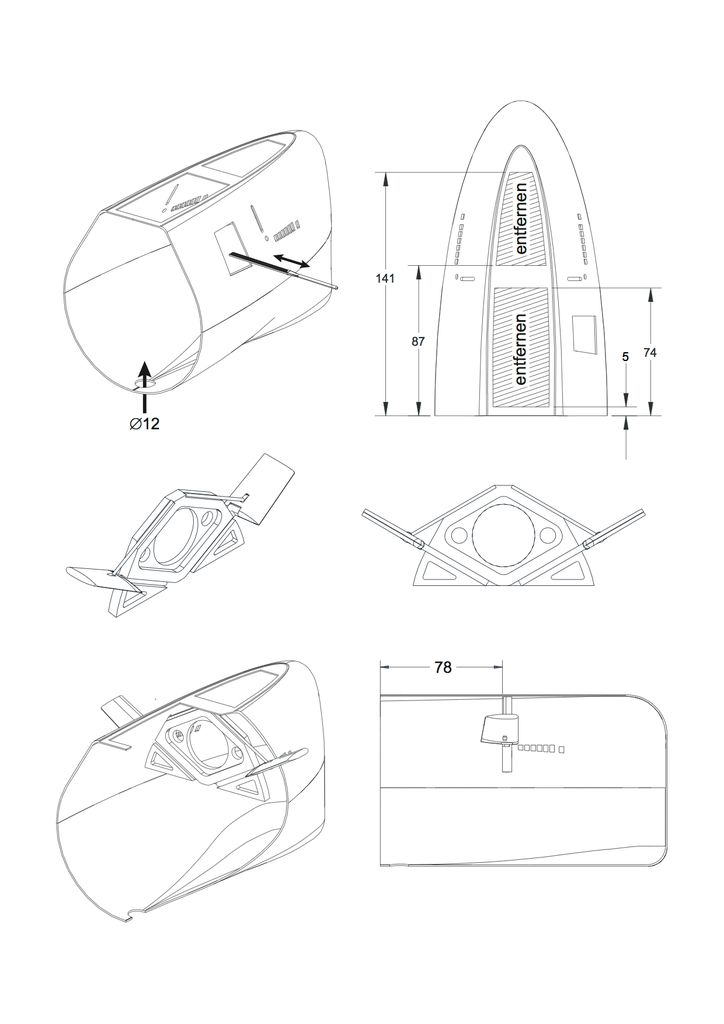
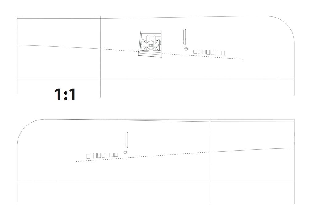
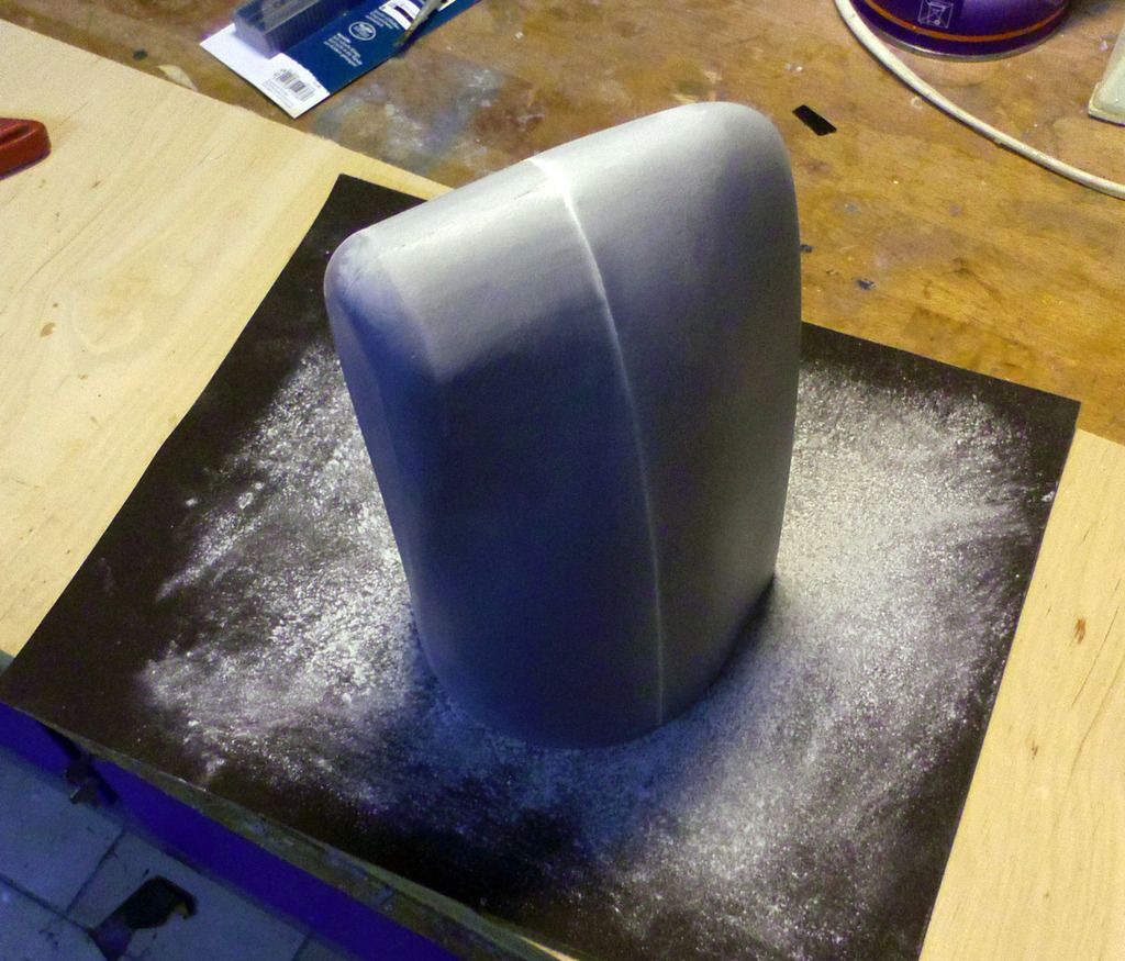
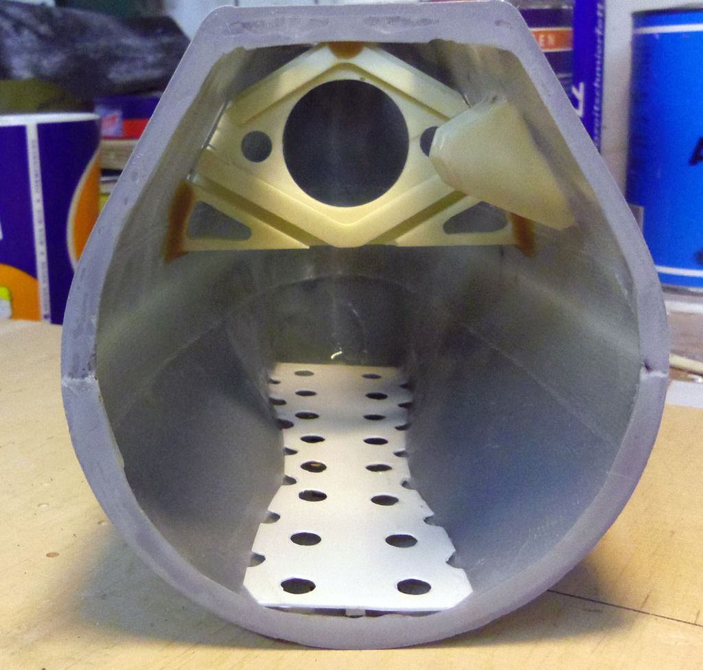
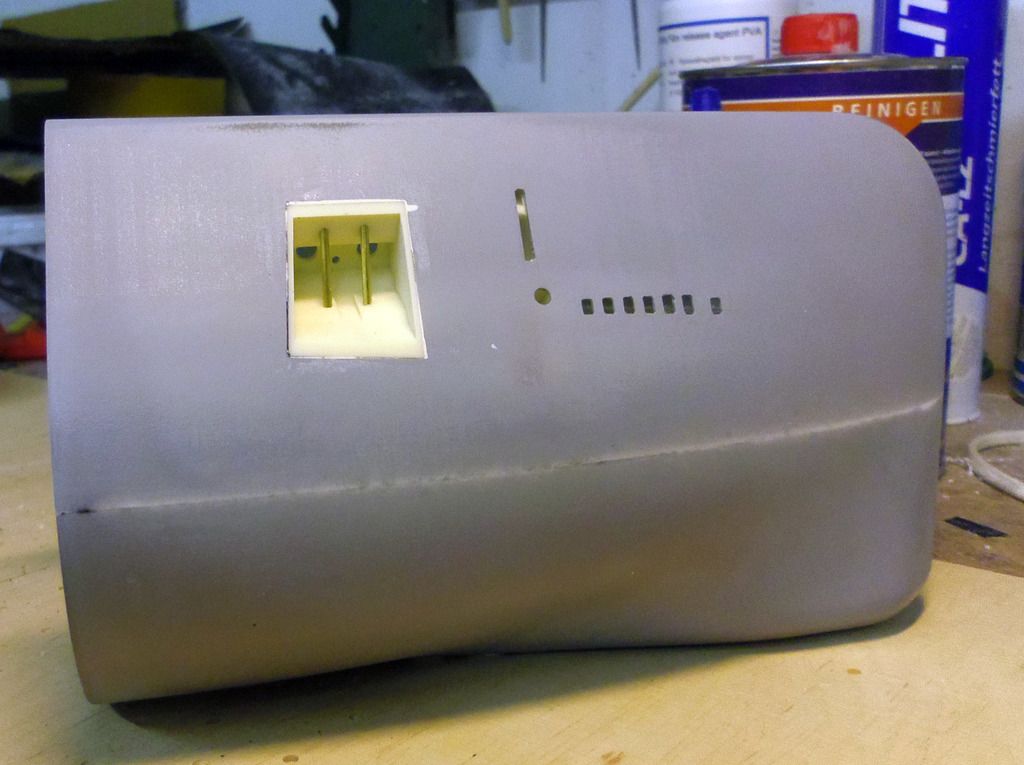
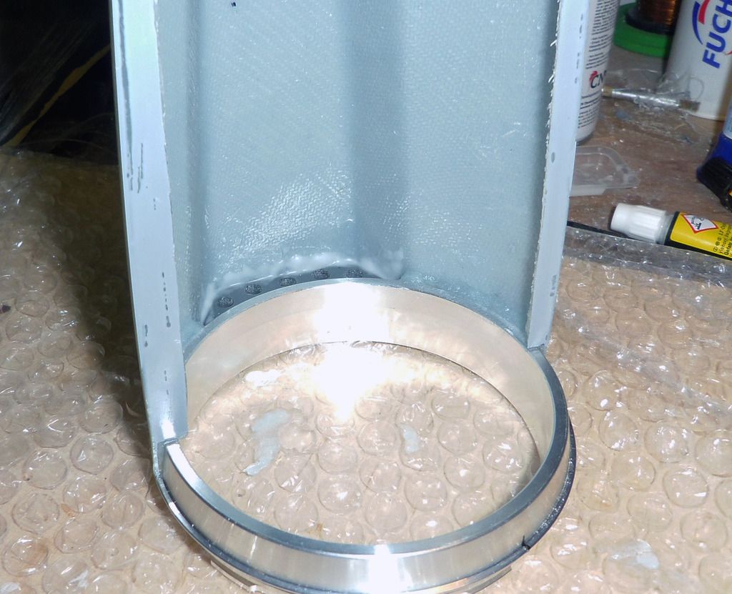
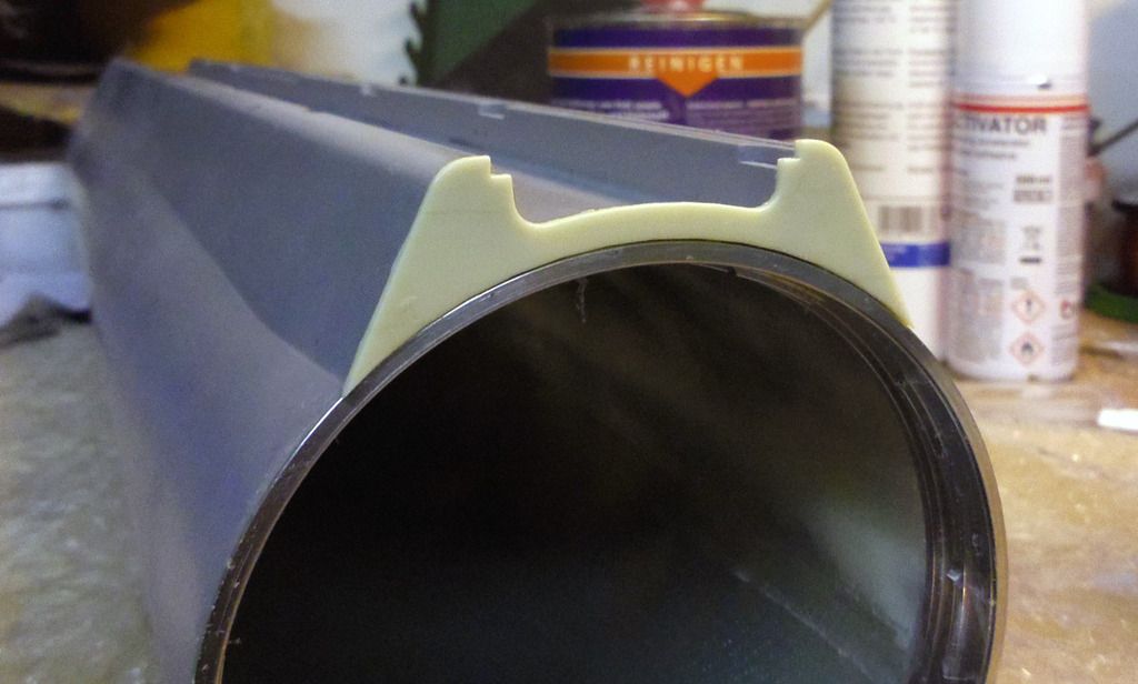
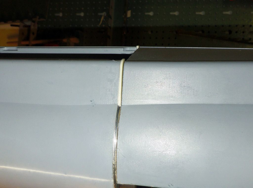
GRPparts: All parts made by glass cloth with epoxy gelcoat as top coat. Moulds were fabricated based on CNC-milled masters. The parts comprise:
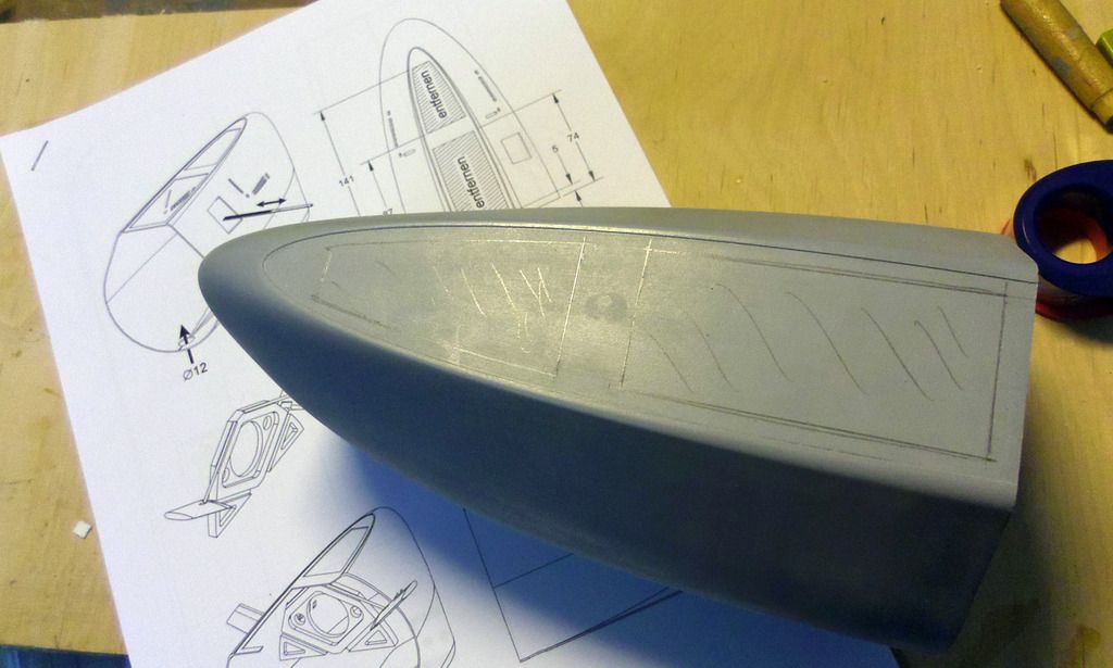
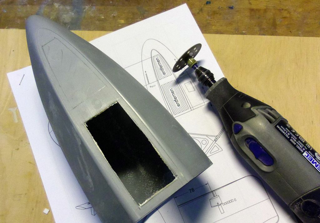
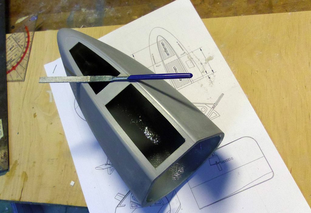
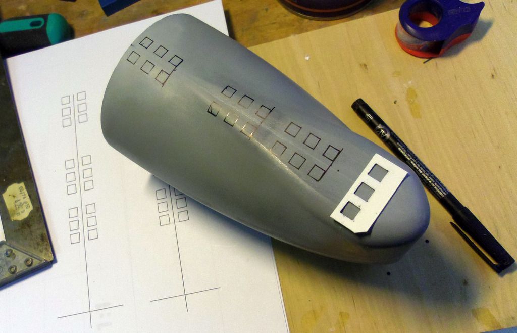
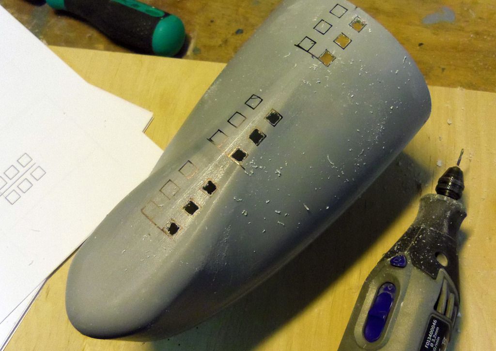
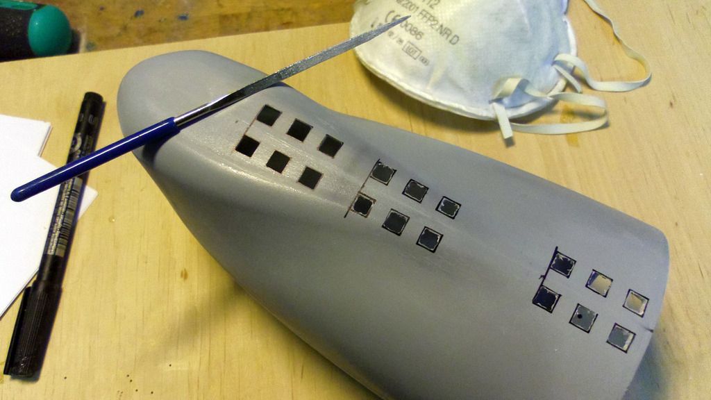
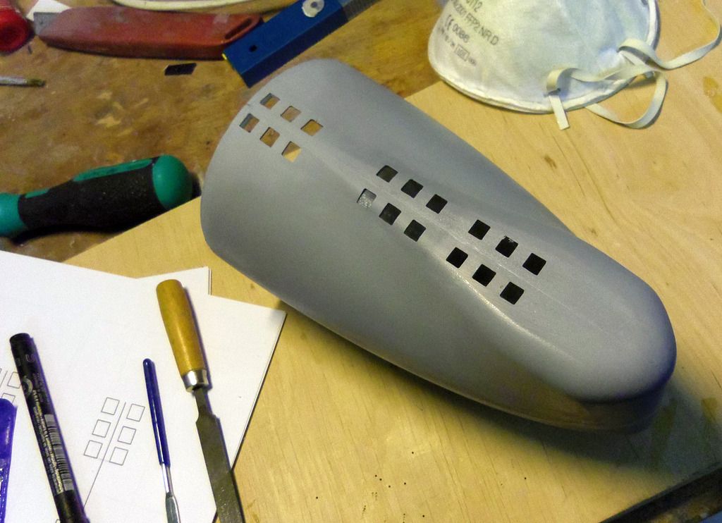
- Bow
- Main hull
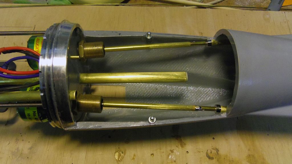
- Stern
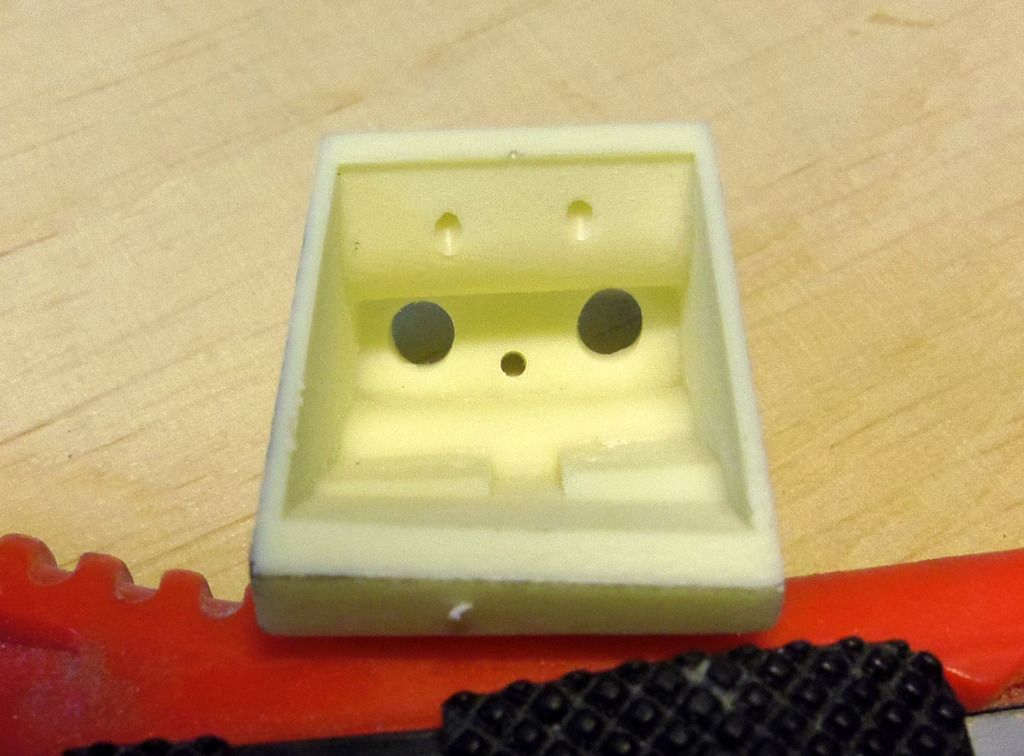
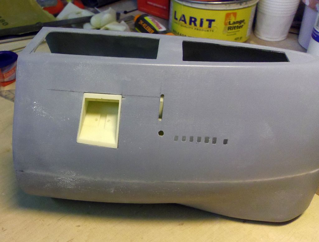
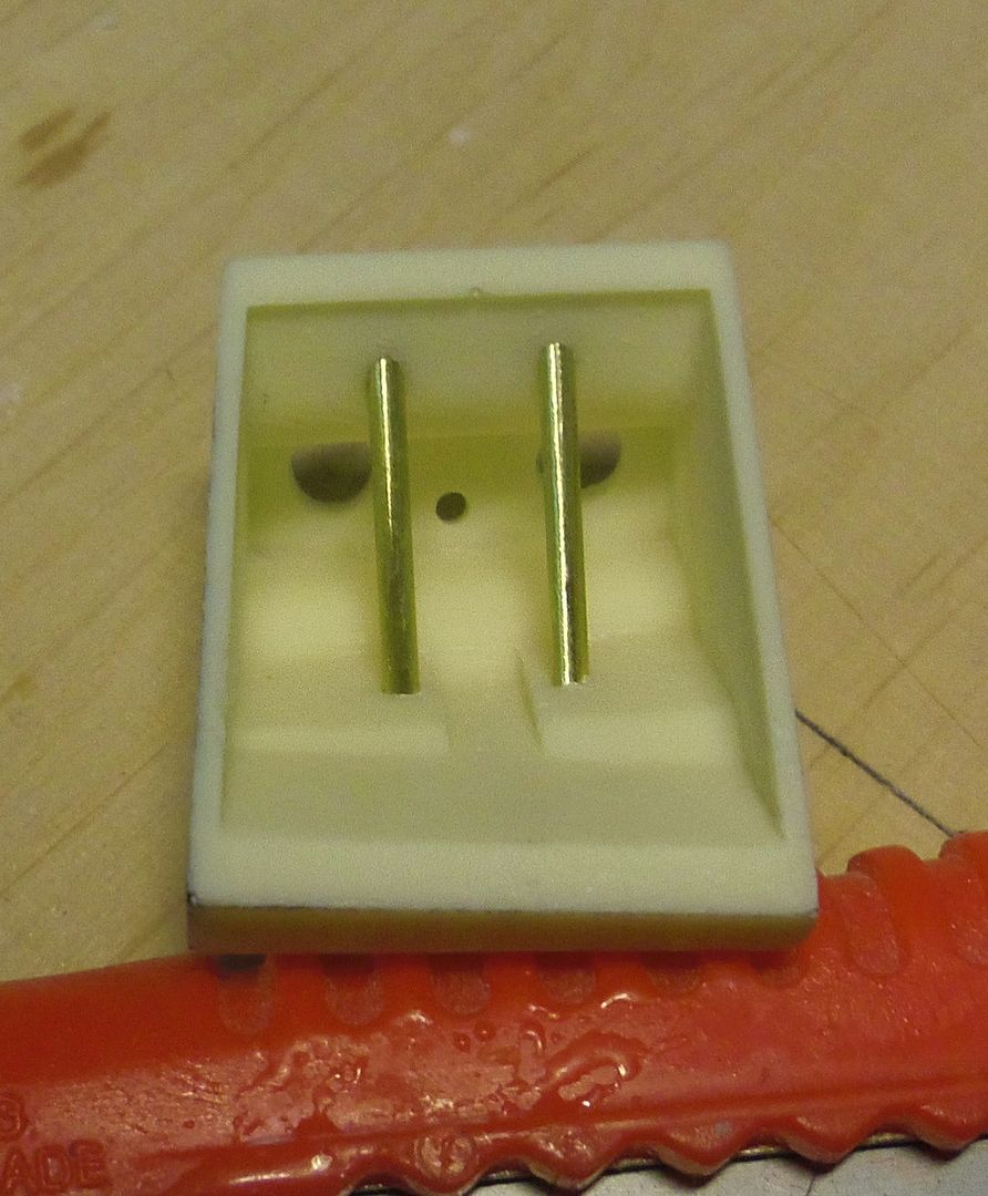
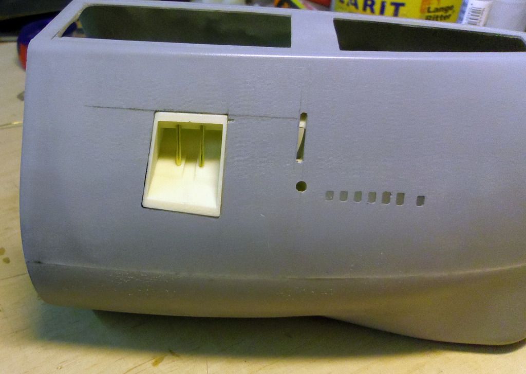
- Service hatch
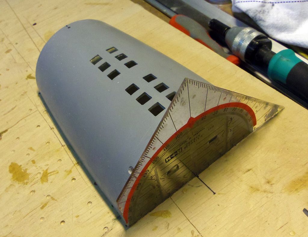
- Sail
- all control planes
- rear bulkhead (not depicted)
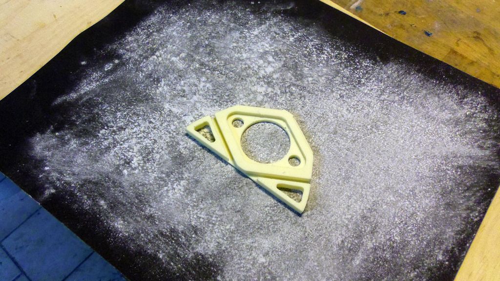
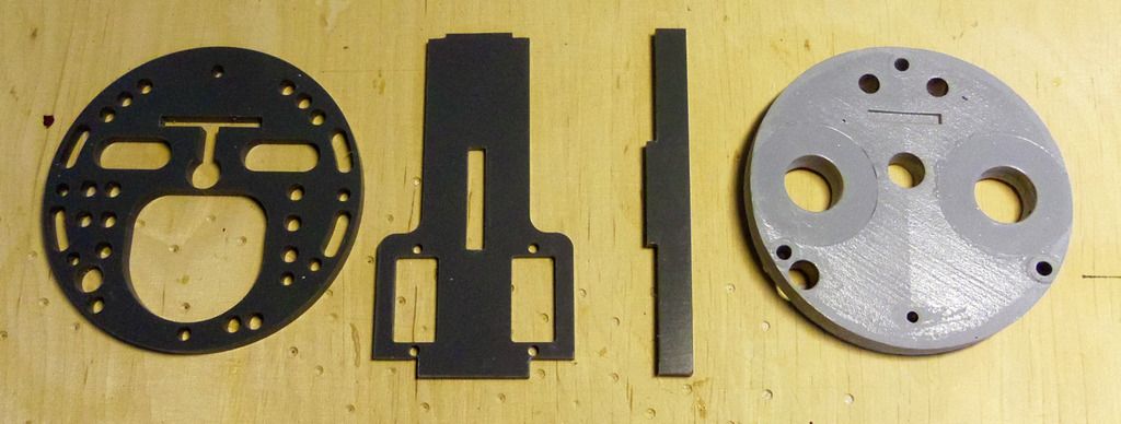
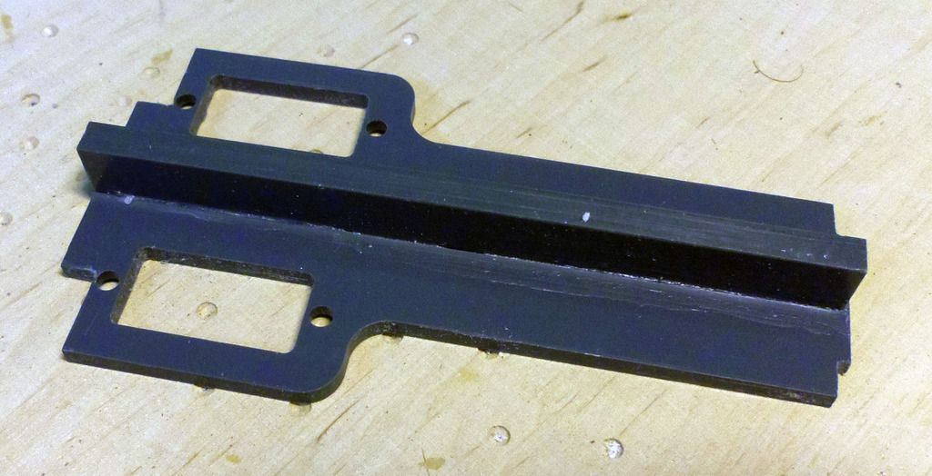
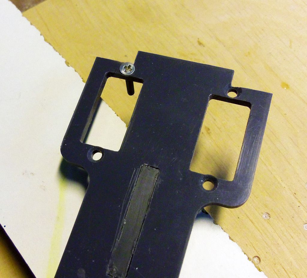
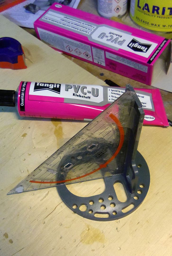
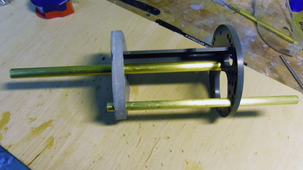
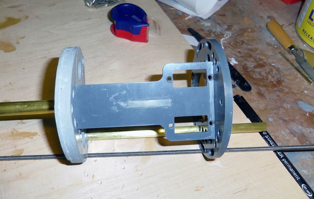
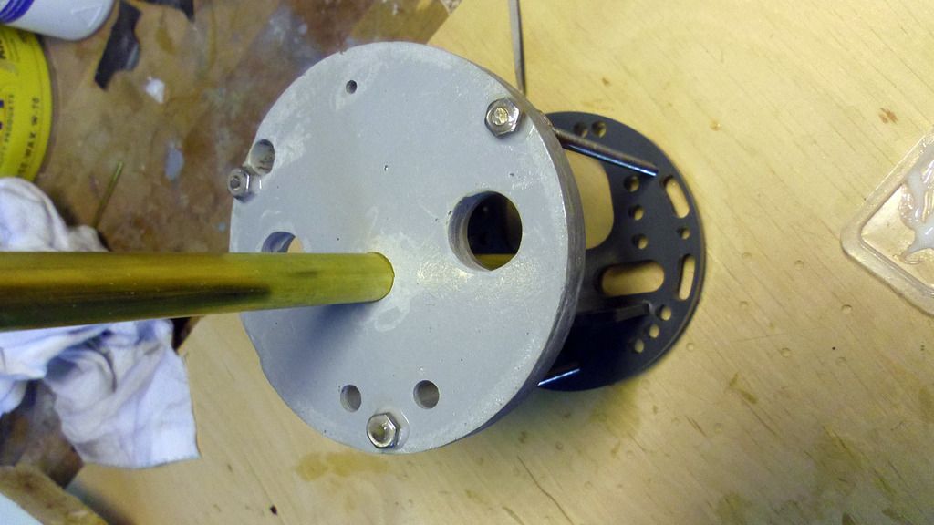
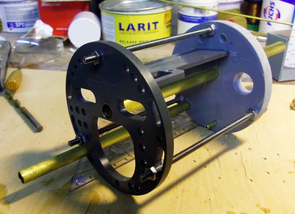
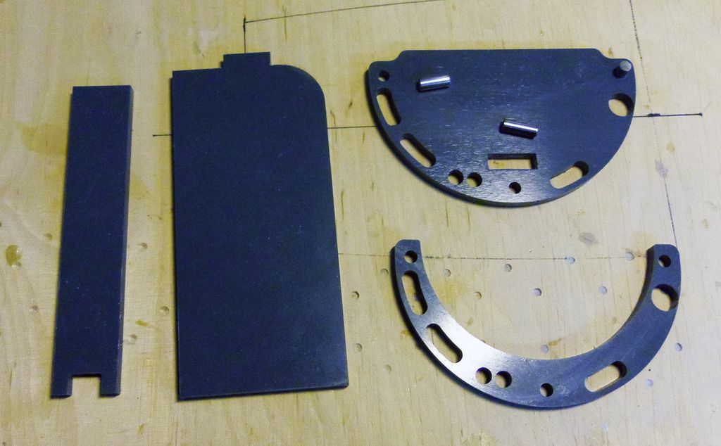
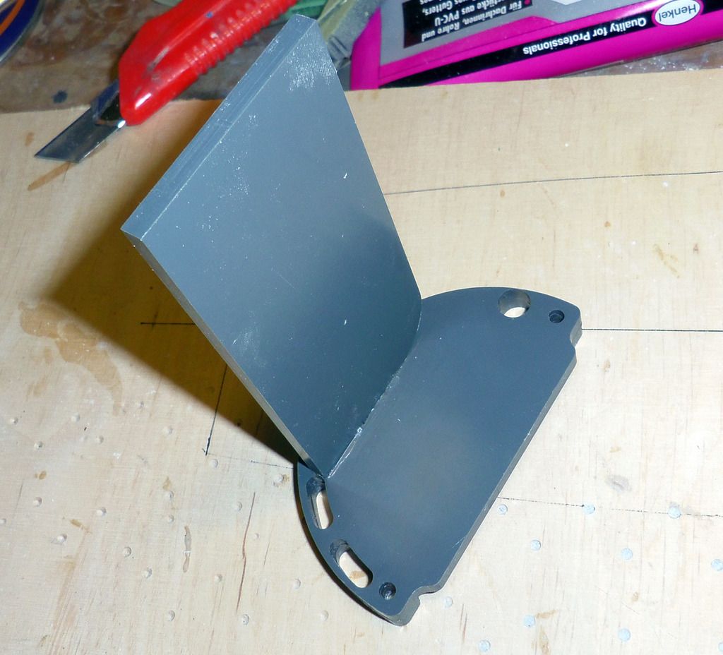
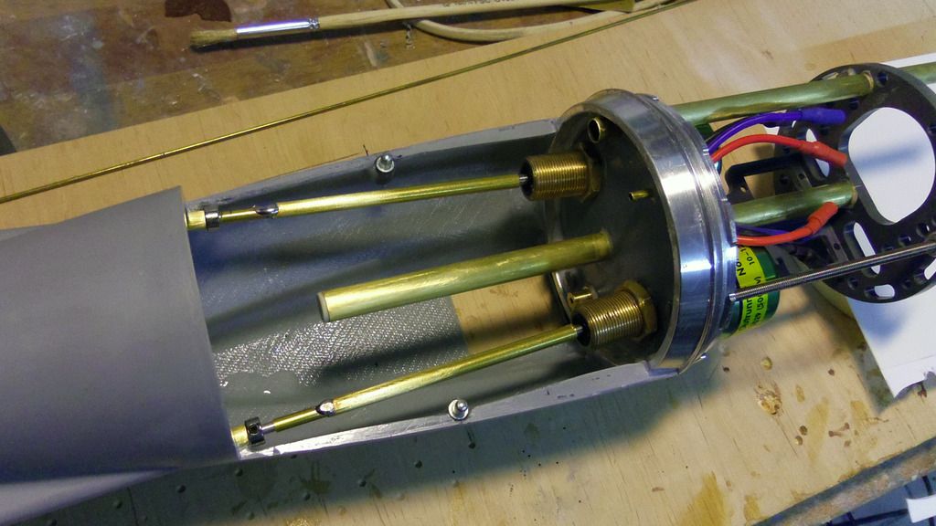
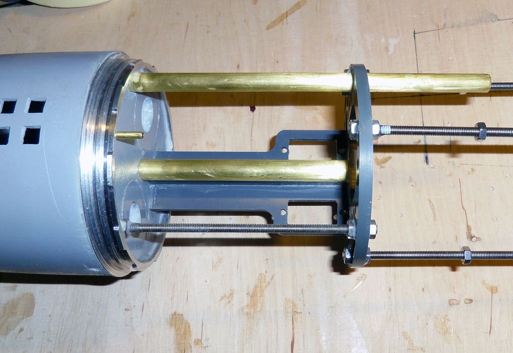
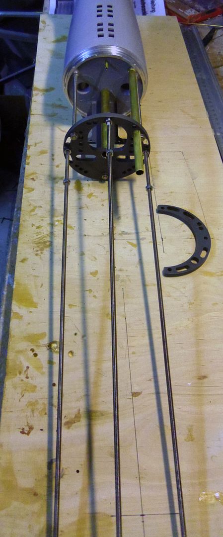
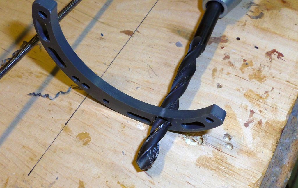
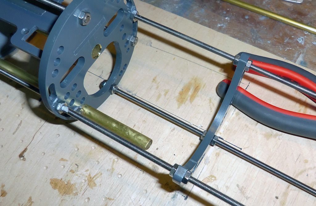
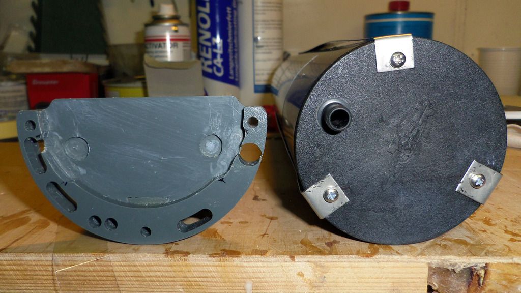
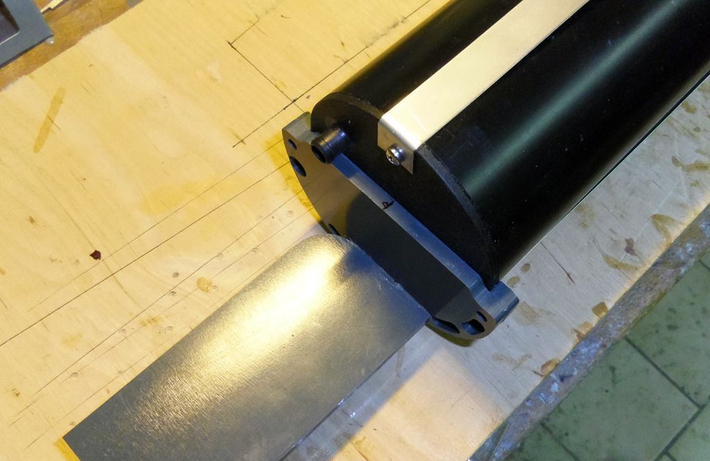
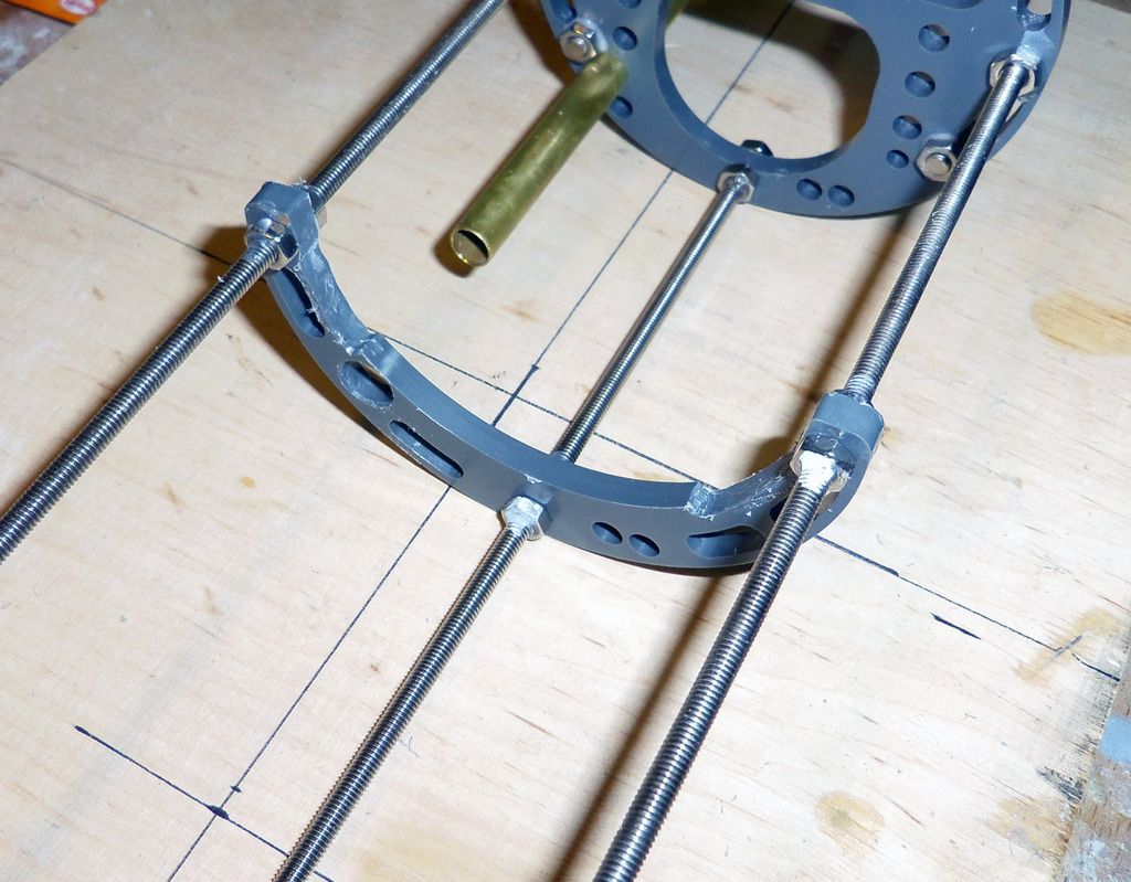
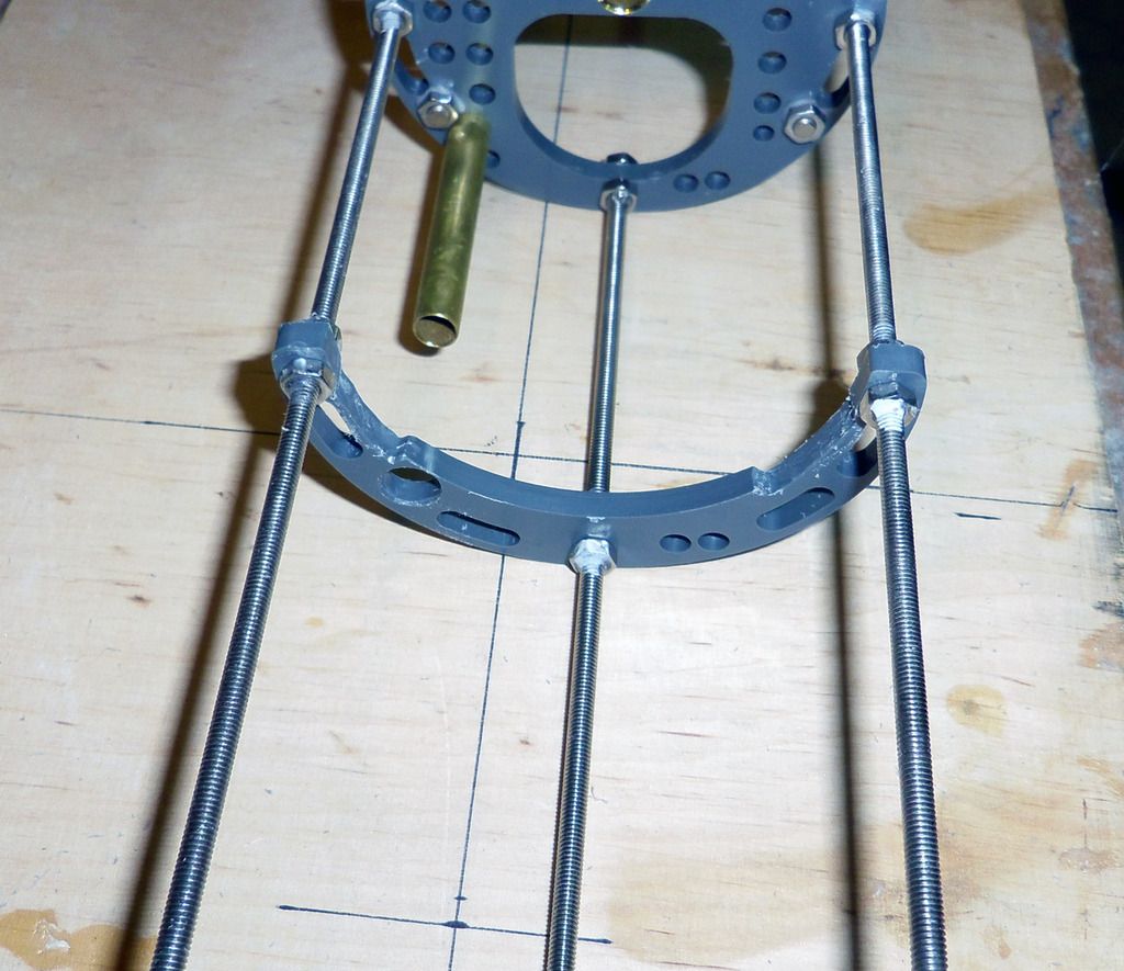
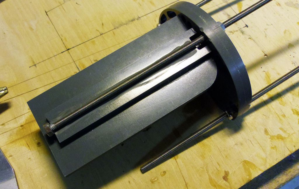
PVC milled parts: All parts for the inner structure, additional pats and the standCNC milled out of 5 mm and 2 mm PVC:
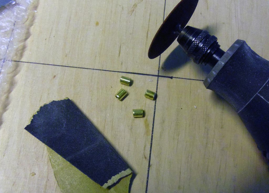
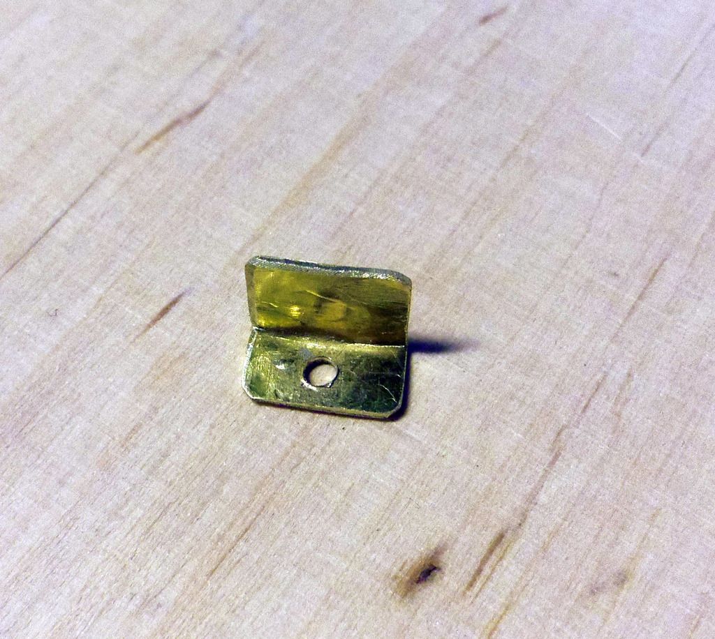
Brass parts: Photo-etched decks and accessories. 2 x scale brass props custom-made by the PropShop (UK)
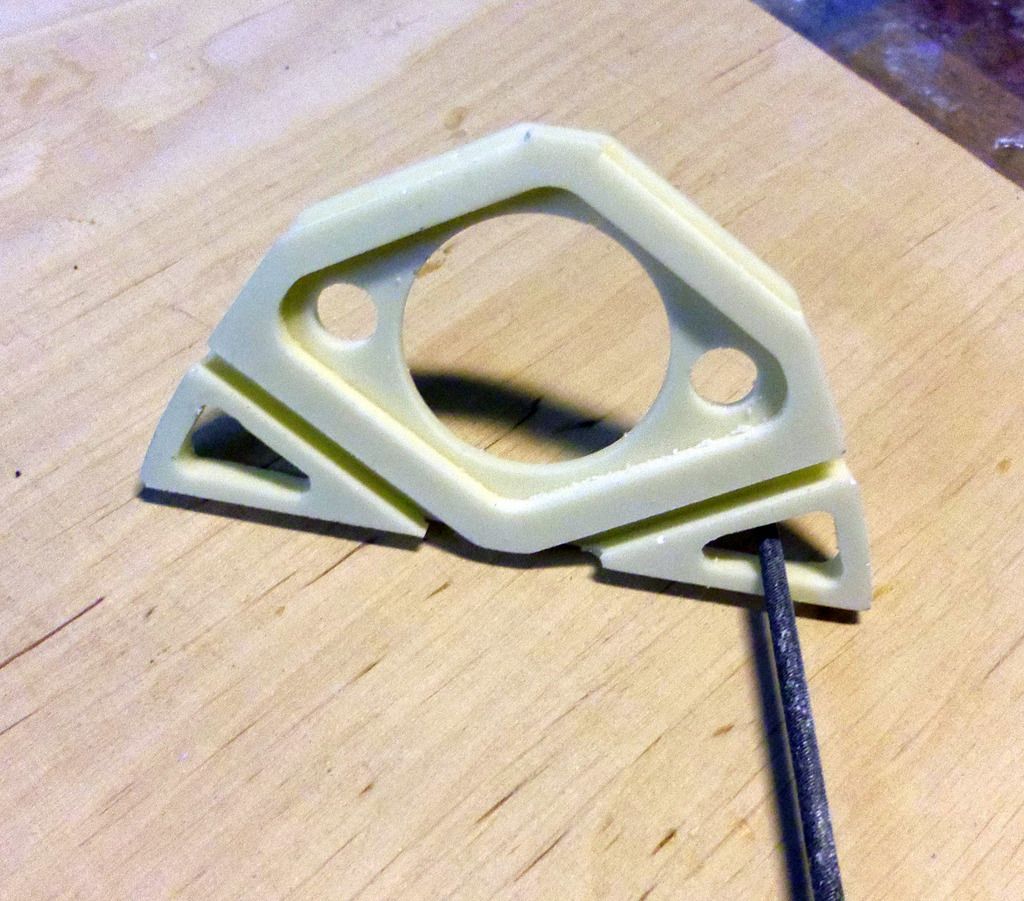
Resin parts: Accessories and structure components made from PU resin:
A set of decals with ships number, name, draft marks...
Bought parts:
Engel Modellbau:
1 x Hall sensor for Compact-Tank Controller CTS2 (1585-H05S)
2 x Compression Fittings 2 mm (3289)
1 x Compact-Tank Controller CTS2 12V (1584-CTS2-12)
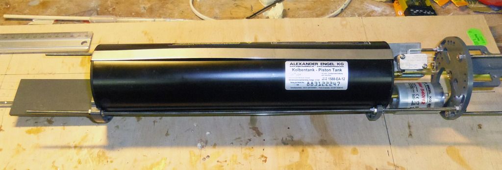
1 x Piston Tank EA 12V 540 -custom made- 1000 ml (1588-EA-12)
1 x Autoleveler SPC2 (1574)
1 x Pressure Switch 3,0 mm (5029)
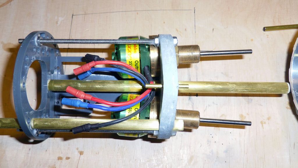
2 x ROXXY® BL-Outr. C35-29 500kv 4989 (RO4989)
Hobby-Lobby Modellbau:
10 x Rail posts 11 mm , 3 Durchzüge (910-11)
2 x Standard Wellenanlage , 170 / 125 mm M4 (5000-05)
Conrad:
2 x Roxxy Bruschless-Control 930
Hacker:
1 x TopFuel LiFe 30C 4100mAh 4S (44100451)
Graupner:
2 x Graupner Servo digital DES 47 (7917)
Brüggen:
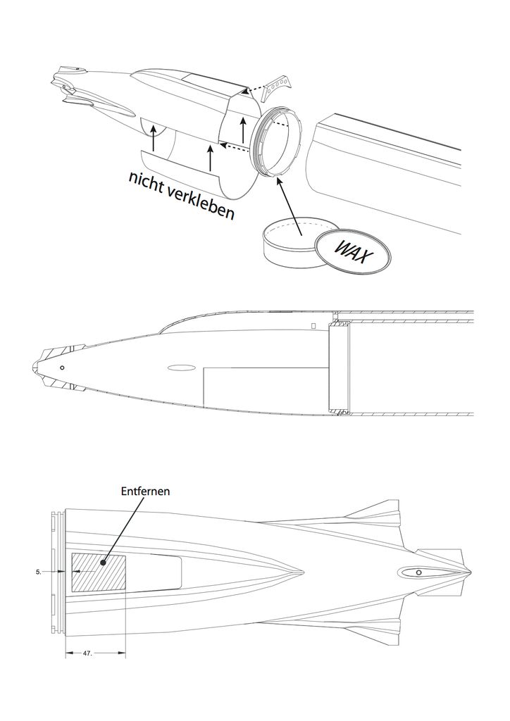
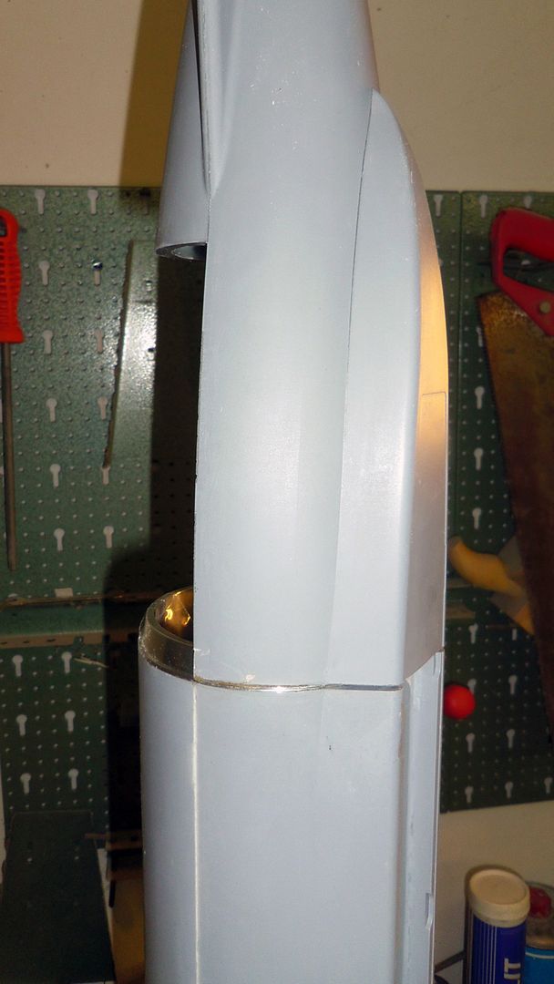
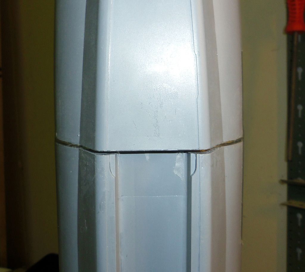
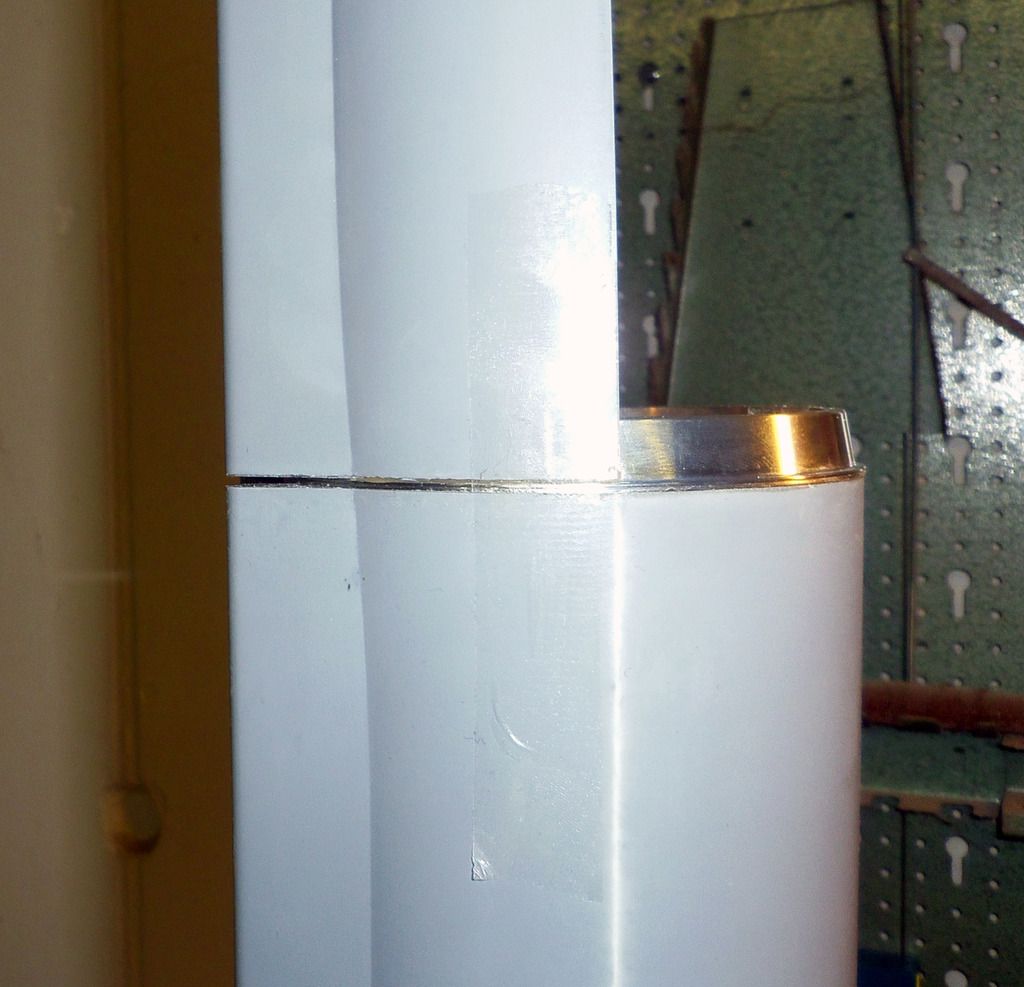
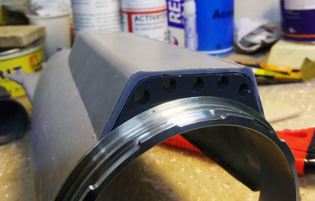
1 x Bayonet Catch 99 mm x 88 mm
1 x Receiver Corona RP8D1
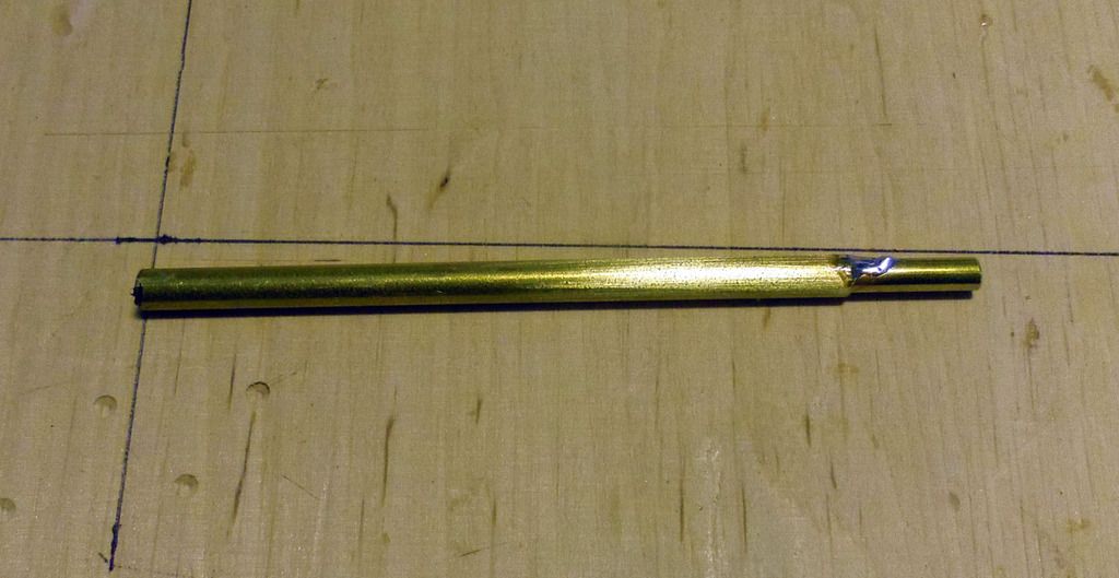
And small stuff like bras tubes, rods, connectors.....
GRPparts: All parts made by glass cloth with epoxy gelcoat as top coat. Moulds were fabricated based on CNC-milled masters. The parts comprise:
- Bow
- Main hull
- Stern
- Service hatch
- Sail
- all control planes
- rear bulkhead (not depicted)
PVC milled parts: All parts for the inner structure, additional pats and the standCNC milled out of 5 mm and 2 mm PVC:
Brass parts: Photo-etched decks and accessories. 2 x scale brass props custom-made by the PropShop (UK)
Resin parts: Accessories and structure components made from PU resin:
A set of decals with ships number, name, draft marks...
Bought parts:
Engel Modellbau:
1 x Hall sensor for Compact-Tank Controller CTS2 (1585-H05S)
2 x Compression Fittings 2 mm (3289)
1 x Compact-Tank Controller CTS2 12V (1584-CTS2-12)
1 x Piston Tank EA 12V 540 -custom made- 1000 ml (1588-EA-12)
1 x Autoleveler SPC2 (1574)
1 x Pressure Switch 3,0 mm (5029)
2 x ROXXY® BL-Outr. C35-29 500kv 4989 (RO4989)
Hobby-Lobby Modellbau:
10 x Rail posts 11 mm , 3 Durchzüge (910-11)
2 x Standard Wellenanlage , 170 / 125 mm M4 (5000-05)
Conrad:
2 x Roxxy Bruschless-Control 930
Hacker:
1 x TopFuel LiFe 30C 4100mAh 4S (44100451)
Graupner:
2 x Graupner Servo digital DES 47 (7917)
Brüggen:
1 x Bayonet Catch 99 mm x 88 mm
1 x Receiver Corona RP8D1
And small stuff like bras tubes, rods, connectors.....


Comment