Engel Akula II Build Questions

Collapse
X
 
  • Time
  • Show
Clear All
new posts
  • JWLaRue
    Managing Editor, SubCommittee Report
    • Aug 1994
    • 4281

    #61
    Originally posted by Charlotte514 View Post
    Hi All - in process of building- have run into the issue of very tight dive plane and rudder linkages. Spoke to Engel but still confused. Do you bend the 2mm linkages in the wet section? How much? Thanks
    The short answer is "yes".....there is some bending required.

    The longer answer is: I have found for both the Engel Type 212a and Akula II that it's best to bend the brass pushrod a little bit at a time until you get a reasonably free servo-to-stern plane/rudder movement. If I recall, on the Akula you'll end up with about 10-15 degree bend? (I'd want to verify that at our next SubRun this Sunday)

    -Jeff
    Rohr 1.....Los!

    Comment

    • Charlotte514
      Junior Member
      • Oct 2019
      • 29

      #62
      Ok Thanks Ralph and JW thanks for the input. We will try and adjust and report progress. First issue where everything did not line up right on.

      Comment

      • JWLaRue
        Managing Editor, SubCommittee Report
        • Aug 1994
        • 4281

        #63
        One additional thought.

        If you do use needle nose pliers to bend the pushrod, be careful not to deform the rod where the bellows is to seal against the rod. If you do you’ll almost certainly have a leak.

        -Jeff
        Rohr 1.....Los!

        Comment

        • Charlotte514
          Junior Member
          • Oct 2019
          • 29

          #64
          Pressure point

          Hey thanks again for the input. We may be being over cautious but cannot figure out how to apply enough pressure to the linkages without possibly breaking the plastic clevis. See attached pic. Should we just use 2 needle nose pliers one for support on the clevis side and one to actually bend the linkage?
          Attached Files

          Comment

          • JWLaRue
            Managing Editor, SubCommittee Report
            • Aug 1994
            • 4281

            #65
            That's what worked for me: 2 needle nose pliers. You are correct to be concerned about the possibility of breaking the clevis. Replacing one is a real PIA.

            -Jeff
            Rohr 1.....Los!

            Comment

            • eckloss
              • Nov 2003
              • 1196

              #66
              Charlotte514, go ahead and be cautious. Last month at the SubComEast run the plastic rudder clevis broke on my Akula II. It was the first time running the boat after adding a lower rudder extension for a better turning radius. I'm guessing the extra oomph needed to turn the rudder was just too much for the plastic. Jeff and I both looked it over and I still have no idea how I'm going to successfully get in there and change it out. Frustrating that a thousand dollar boat is crippled by 2mm of plastic.

              Comment

              • JWLaRue
                Managing Editor, SubCommittee Report
                • Aug 1994
                • 4281

                #67
                Erich,

                We're going to need a needle nose plier that is curved or (better) is one with a right angle bend to replace that clevis. Unfortunately, I don't have one.

                -Jeff
                Rohr 1.....Los!

                Comment

                • Ralph --- SSBN 598
                  Junior Member
                  • Oct 2012
                  • 1417

                  #68
                  Maybe I can help.
                  I have had a clevis break and I modified the lower rudder to help turn the boat.

                  Starting with the clevis.
                  I did some mdifying and came up with a solution.

                  This is the original clevis.
                  The top of the pin broke off and is inside the clevis frame.
                  No longer works.

                  Measured the pin to see about getting a replacement at the hobby shop.
                  Measures .0575" diameter.
                  Hobby shop said, they do not have metric sizes.

                  Okay !
                  Let's see if I can modify this one. or build one out of brass.
                  Click image for larger version

Name:	clevis01.jpg
Views:	1
Size:	35.8 KB
ID:	133813

                  The nylon clevis is a press fit on tot he brass tube extension.
                  Took a bit of effort to twist it off.
                  That is good as it will not just slide off.
                  Found a scrap of fuel tubing and cut a clevis keeper.
                  Found a piece of 1/16" brass rod.
                  It is too big but I chucked it up in the Dremel and got after it with a file.
                  Made a shoulder that was .0574" in diameter. Yep, I took too much off. But .0004" is not a problem here.
                  Bent the pin in to an L shape and add a couple of other slight bends.

                  Parts.
                  Click image for larger version

Name:	clevis02.jpg
Views:	1
Size:	27.9 KB
ID:	133814

                  I ground a shallow groove in the top of the nylon clevis for the rod tail to sit in.
                  This will keep it from rotating off the clevis.

                  Finished rebuilding of the clevis.
                  Now all I have to do is get in there on to the rudder horn.

                  The plan is this.
                  The pin has a smaller diameter end that goes in to the small hole on the lower clevis arm.
                  I made a step from the main pin to the point.
                  This is so I can lift the pin and set the pin on that shoulder keeping the clevis open enough to pass over the brass rudder horn.
                  Once I have it over the hole in the horn or near, I can bump the pin and it will drop off the shoulder and will have pressure on it until it drops through and bottoms out in the lower clevis arm.
                  Click image for larger version

Name:	clevis03.jpg
Views:	1
Size:	26.6 KB
ID:	133815

                  Turns out, there is not enough room to get two long tweezers in there and still see what I am doing.
                  Spent most of the morning trying to make this work.
                  Finally called it quits!

                  Option 2, suggested by Tom.
                  Z bend.
                  At first I didn't think this would work but as I was messing with the modified clevis, looking in the tail cone. the Z bend looked like it might work if I modified the bend 90 degrees.

                  Made this brass rod with a 90 degree Z bend.
                  I was able to get it in to the hole of the rudder horn but could not twist it.
                  Did some filing on the curve corners and got it to the turn.
                  Click image for larger version

Name:	clevis05.jpg
Views:	1
Size:	29.6 KB
ID:	133816

                  Next was to connect this rod to the control rod.
                  Back to not having enough room for 2 tweezers.
                  Made a wire hook to help hold the control rod up, level.
                  Yep, this did not work either.

                  Time to make an old fashion control rod connector.
                  Solder a wheel collar to one of the rods.
                  Making sure the wheel collar set screw is pointing in the right direction when every thing is aligned.
                  That is a 1/16" wheel collar with t he 1/16" brass rod soldered to the outside edge in a groove I put on it.

                  The rod in the boat is less than the 1/16" so there should be plenty of room.
                  Click image for larger version

Name:	clevis04.jpg
Views:	1
Size:	27.6 KB
ID:	133817

                  Comment

                  • Ralph --- SSBN 598
                    Junior Member
                    • Oct 2012
                    • 1417

                    #69
                    I lengthened the front of the rudder to get more the flow of water pressure on the front of the rudder to help reduce the servo torque needed.

                    I made one side on shape and the other a different shape to see which side did a better job of turning the boat.
                    The blunt rounded shape won out.

                    Not the effectiveness of this did not give me what I was hoping.
                    I did tighten the turning circle about 3' to 4' but the boat still needs a lot of space to make a complete circle.

                    I looked in to the tail cone to see if I could get more turn on the rudder shaft.
                    I already have it to were the yoke lightly touched the propeller shaft in both right and left turn.

                    Only way to get more turn would be to remove the rudder yoke and reshape it to let the yoke move more towards the shaft
                    I did not do that.

                    Comment

                    • Charlotte514
                      Junior Member
                      • Oct 2019
                      • 29

                      #70
                      Solution for bending the 2mm control rods

                      That was a PIA - I was tempted to send the dive-plane/rudder assembly back to Engel. Luckily my buddy who is doing the electronic configuration son had the best solution. We used an old GWS micro gear puller to bend the rods. Rough machining job but it worked amazingly well.
                      Attached Files
                      Last edited by Charlotte514; 12-08-2019, 06:14 PM.

                      Comment

                      • Charlotte514
                        Junior Member
                        • Oct 2019
                        • 29

                        #71
                        Next challenge is to get the lead weights positioned. Any hints? How precise does this positioning have to be? Thanks

                        Comment

                        • Ralph --- SSBN 598
                          Junior Member
                          • Oct 2012
                          • 1417

                          #72
                          I followed the instructions and it only took a small weight move around on the tec rack to find level trim.
                          I am going to copy and past what I did from my build log.
                          Because the installation of lead weight is spreate out in the log.
                          ---------------
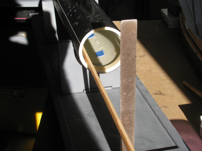
                          While it was early and when the sun comes through the shop door, I decided to go with marking the inside of the hull for the ballast weights.
                          Need a center line.
                          Easiest way I could think of to do that was to use a square to level the hull in it's stand.
                          By using a square and another square clamped to it, I could cast a shadow that I could use to get the hull level.

                          The shadow from the 2 squares was used to get the forward planes level by splitting the shadow in the rear of the planes.

                          Then I moved the hull until the shadow was centered in the opening in the hull.
                          Moving the hull side ways I got the shadow to split the hull down the center of the deck.
                          Turns out that the shadow from the sail centered right on the forward emergency buoy. (good reference)

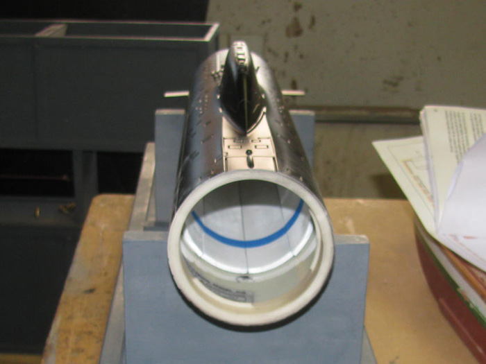
                          With the boat level and the shadow centered down the hull, I could use the shadow in the hull to place marking tape on the center line.
                          Using 2 long sticks I place the pieces of tape.
                          (Tape to be removed later)

                          This process took me about 15 minutes.
                          I have used this method of shadows to make center lines and long straight line on other projects in the past.
                          I found that in the field working, I could almost always get a shadow line for job layout.


                          Hull inside centerline in place.

                          Time to install the ballast bars.
                          I sanded the lead bars and painted them white.
                          I put double face tape on both ends of each bar.
                          Checked my center line down the bottom of the inside hull.
                          I slid 1 bar in and moved it around until it was inline with the center line mark.
                          I did not remove the paper from the double face tape so I could side it around.

                          Took the second bar and removed the double face tape paper.
                          I slid this bar in upside down on top of the first bar.
                          When it was in to the rear placement mark, I flipped the bar on it's side and made sure it was tight against the first bar without moving it and was lined up on the insert mark.
                          When I had it where I wanted it, I flipped the bar over on to it's double face tape.
                          Pressed it down to secure the tape.
                          Then I removed the first bar and remove the paper from the tape.
                          Did the same as the second bar and then flipped it in to place.

                          Bar 3 and 4 will be put in place without removing the paper tape covering.
                          I used masking tape to hold them in place.
                          This is so, I can move bar 3 and 4 during trimming, if I need to.

                          =======================

                          Comment

                          • Charlotte514
                            Junior Member
                            • Oct 2019
                            • 29

                            #73
                            Final trim

                            She does not leak! Trim off to the starboard, bow low. Those I understand (I think) I can adjust. Sits below waterline though without using the small weights at the batteries.
                            Should the waterline be right at the white line?
                            Attached Files

                            Comment

                            • Ralph --- SSBN 598
                              Junior Member
                              • Oct 2012
                              • 1417

                              #74
                              I trimmed my Akula II with a full ballast tank to submerge the boat completely and slowly go to the bottom. (in the bath tub.
                              THen emptid the ballast tank and found that the boat does not rise to full waterline.
                              My boat was about 3/16" low in the water.
                              I choose the high waterline for being able to bottom the boat.
                              Withthe boat stopped, at 5' away from the shore and no one can tell.
                              When mving it is even harder to tell the boat is low in the water.

                              That small weight, mine is on the frame around the batteries.
                              It took a few tries t get the boat level when submerged.
                              Does not matter on the suface.
                              I put it low on the side that needed to go down to get the sail upright.
                              I used this small weight to trim for and aft and to roll the boat to bring the boat upriight.

                              I also think that the two upper long weights are farther in the hull to help level the boat.
                              Maybe 1/2".

                              I will be check this Saturday at the pond.
                              Maybe Friday when I charge the batteries.

                              Comment

                              • JWLaRue
                                Managing Editor, SubCommittee Report
                                • Aug 1994
                                • 4281

                                #75
                                You'd like to be as close to the white waterline as possible when surfaced. Does the boat fully submerge?

                                It's difficult to tell from the photo, but the first thing I would do (if the boat does fully submerge with a full piston) is to remove some weight from the bow area. Then see how it sits.

                                -Jeff
                                Rohr 1.....Los!

                                Comment

                                Working...
                                X