
Keep the photo's coming, I'm loving it.
-
-
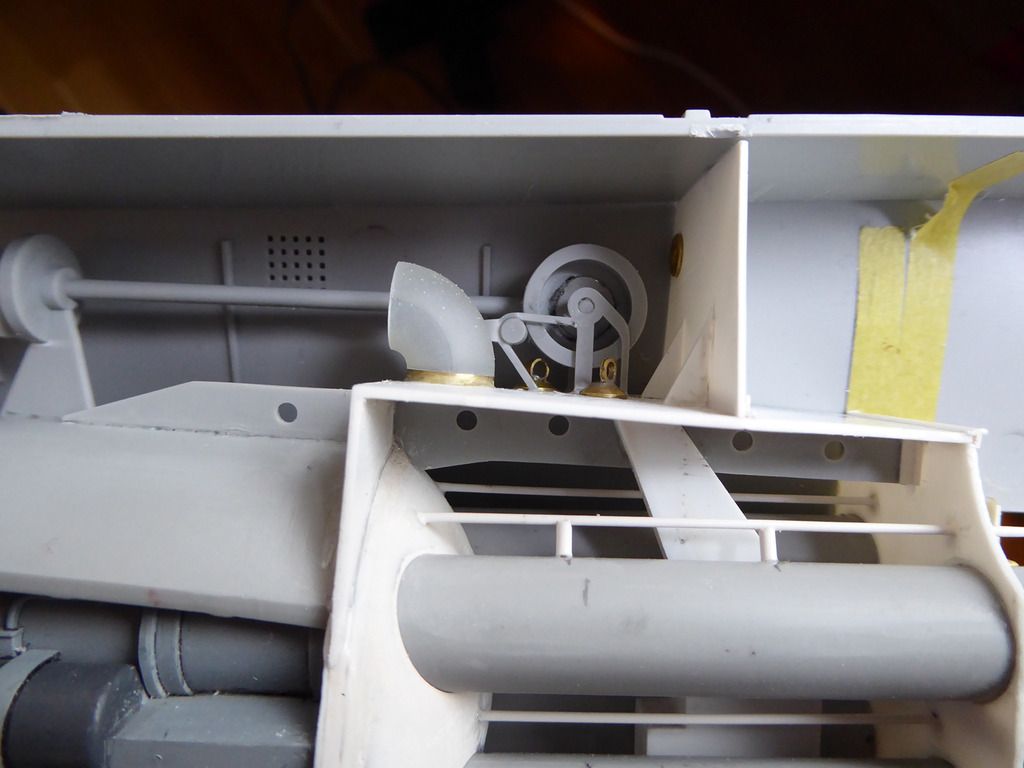
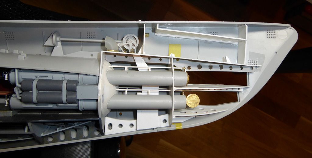
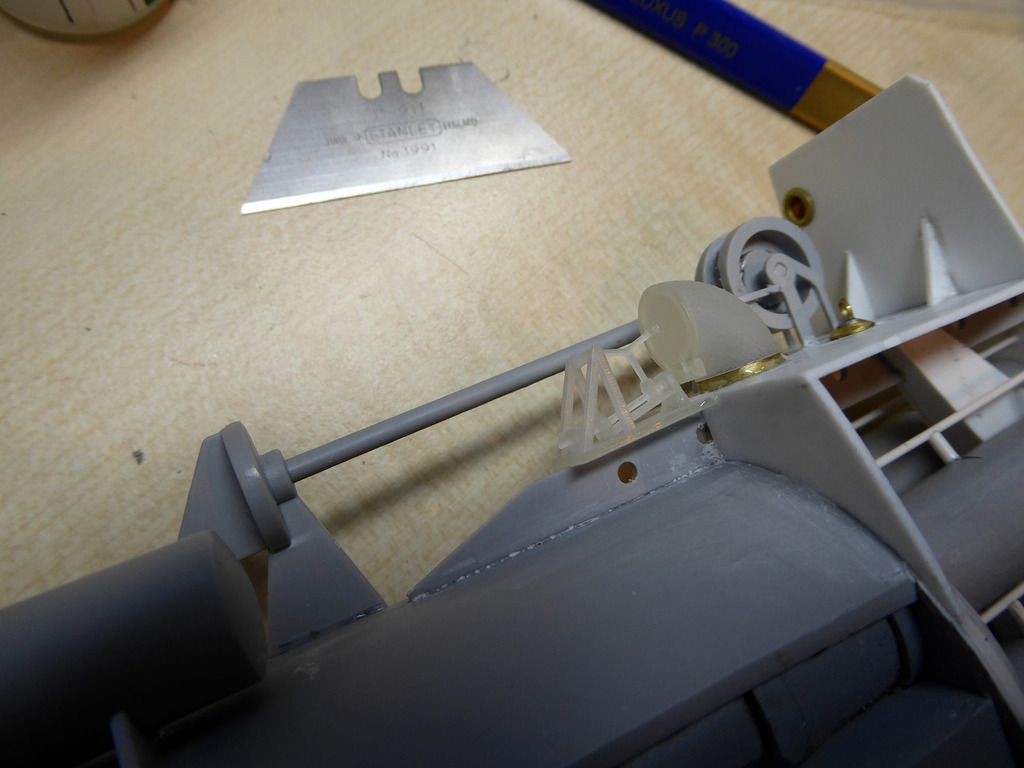
Continuing with adding details around the muzzle door and the vent valve:
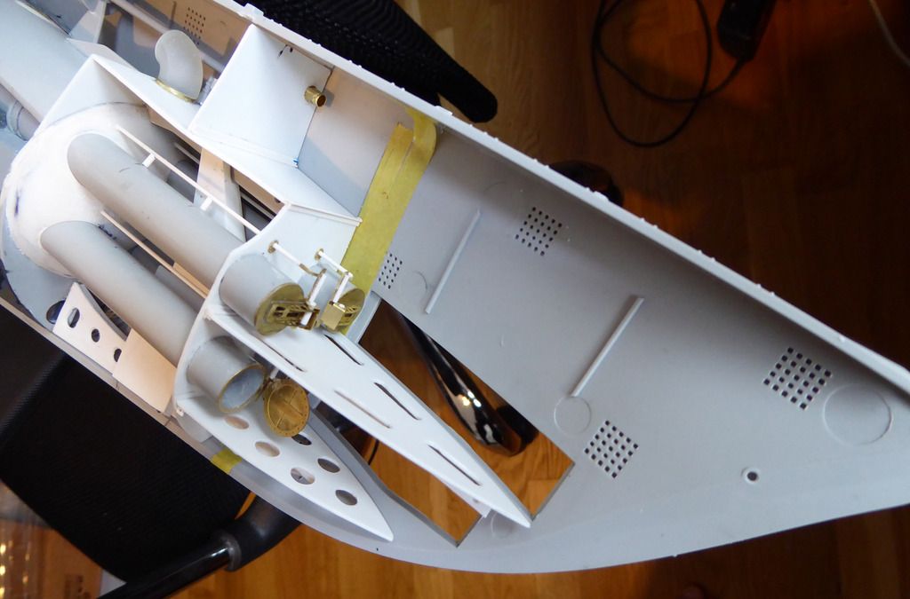
The vent valve is a knee shaped exhaust and it will get a hatch and the actuation mechanism:
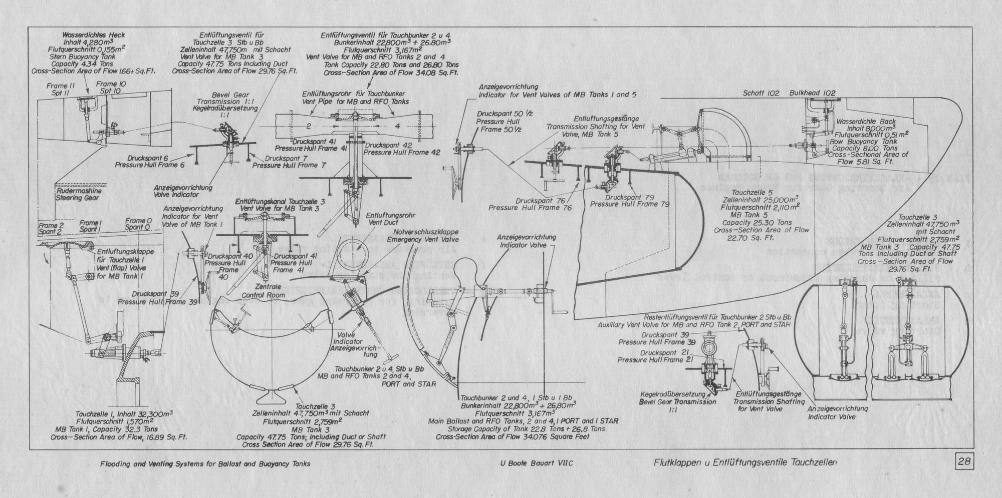
For those who are interested ho the venting system on a VIIc worked, here's a nice picture:
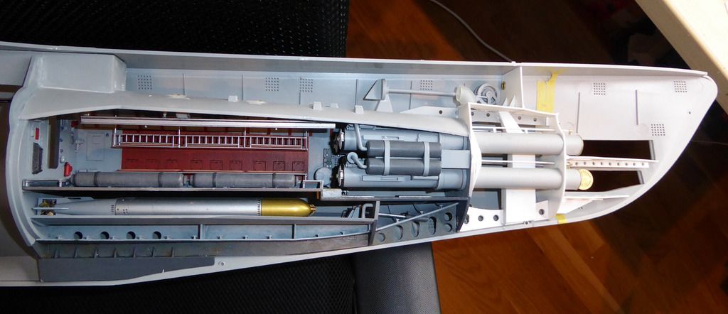
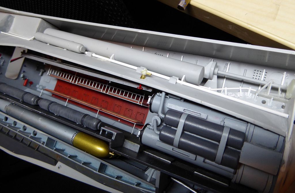
And everything still fits nicely in the hull:
Comment
-
as always, great work. the level of detail you are adding is amazing.
on a side note, Dave Burkett and I went to the IPMS show here in Richmond last week, and Dave picked up this kit... wait for it... for $200. that's an amazing price for this monster.Comment
-
That's a good price....paid 350 Euros for mineComment
-
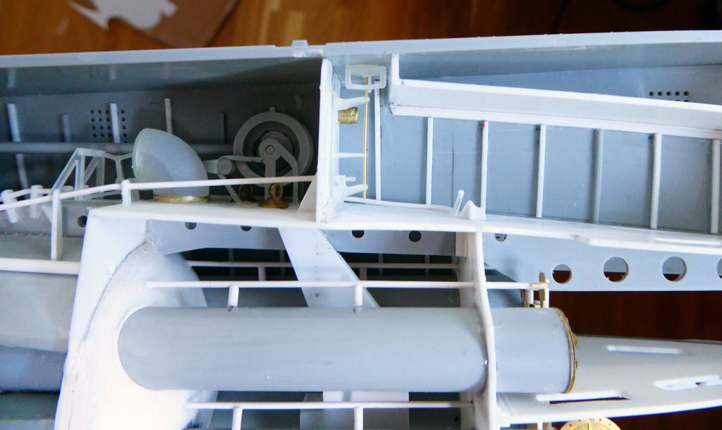
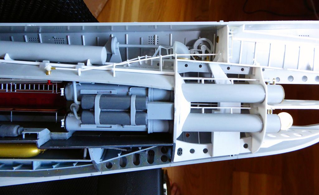
Almost finished with the bow structure. Added the bulkheads for the forward buoyancy tank. A tank that surfaced is above the waterline and which helps to limit the bow cutting into heavy seas. When submerged, this tank is vented like a standard ballast tank.
I've also reworked the supports fr the compressed air bottle that was located in the buoyancy tank, to make them a bit more like 3D objects and not just flat pieces of styrene.
Comment
-
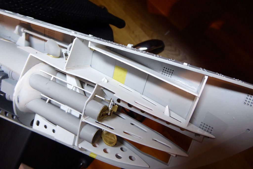
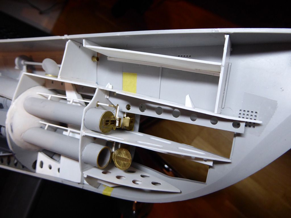
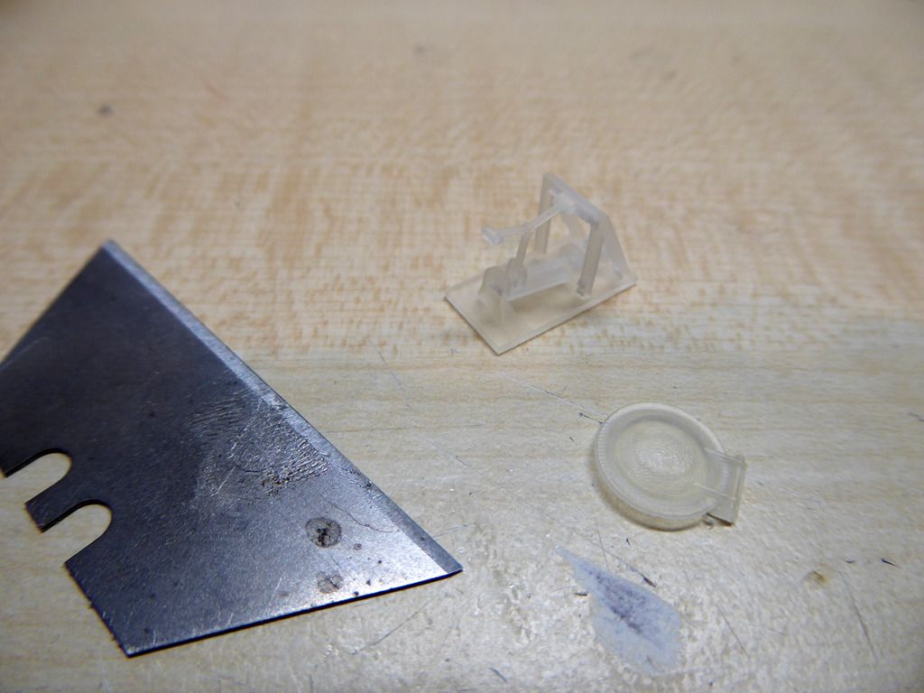
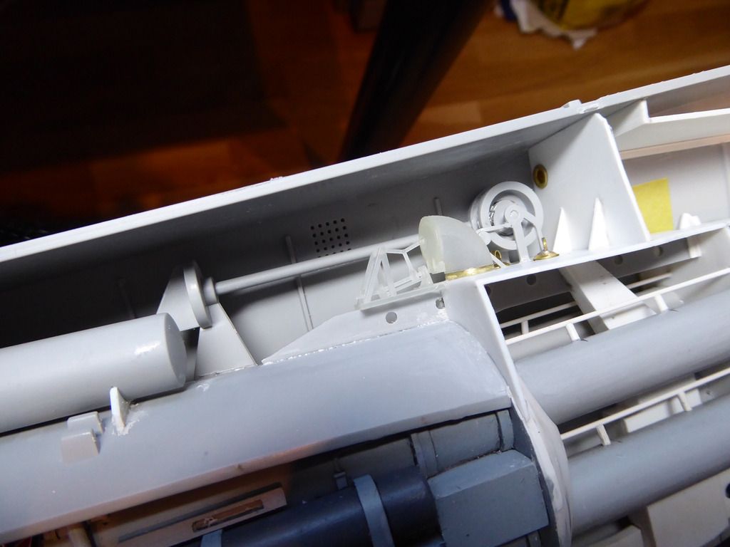
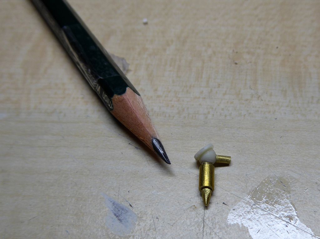
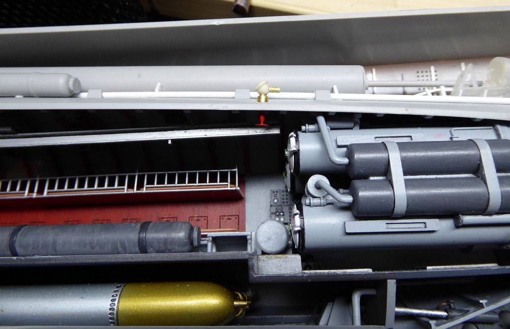
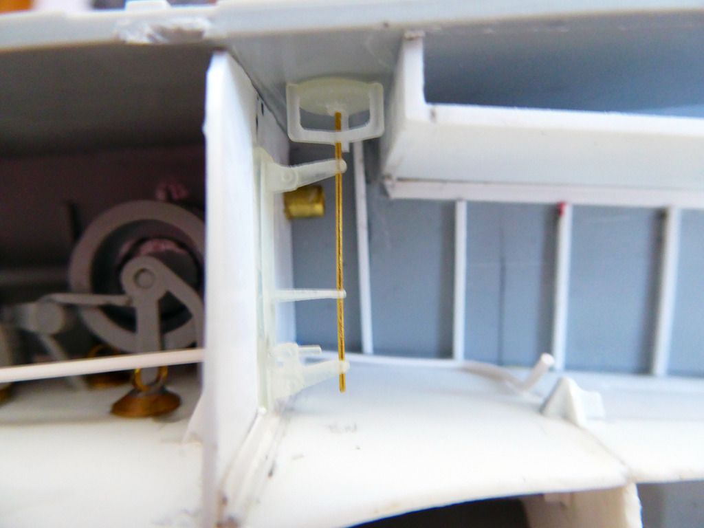
O.k. the 3D-printed pats for the vent valve actuator and the respective hatch arrived.Basically it was a thread rod-driven knee joint.
The valve was driven by a hand wheel in the control room. Outboard transmissions drove the thread road. Those will be added later. Looks quite good installed:
Comment
-
Slightly off topic:
May I ask what diameter the rods of in the valve actuator have? And some details on the used print material & service.
I'll be starting soon on a 1:3.6 T-28 aircraft cockpit interior for a buddy; yet some parts will be too small for my printer. Need to decide to print or make manually, hence the question.Comment
-
Diameter is around 0.6 mm. Service is Shapeways.com. Material is frosted extreme detailComment
-
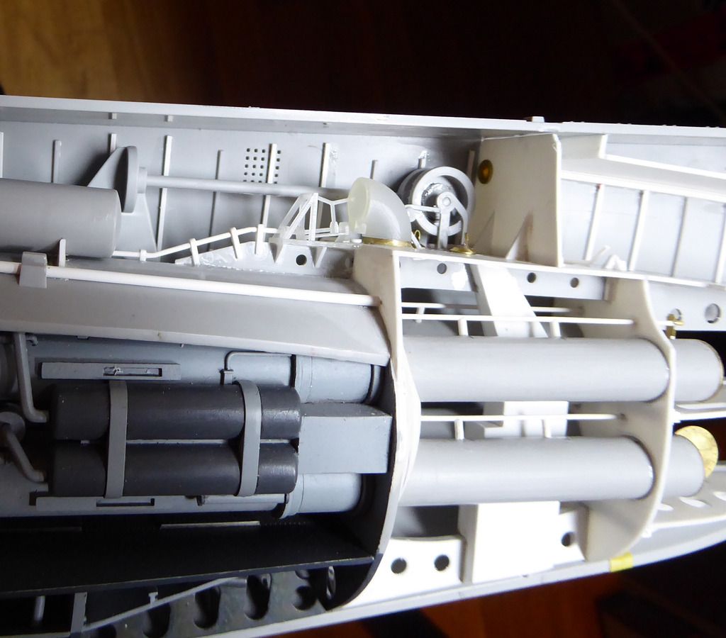
Wrapping up the bow section. I began adding the ribbing on the inner sides of the hull. Also the front torpedo storage container is installed (I added some mounts).
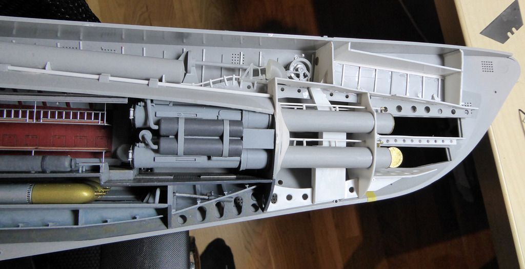
Also added some supports to the platform of the vent valve actuator of ballast tank 5. And it got its drive shaft.
The bow buoyancy tank will also get a 3D-printed vent valve. It was operated from the bow torpedo compartment by a handwheel that actuated an angular wheel gearbox.
I reproduced the gearbox using brass and resin:
Gearbox glued into place, PE handwheel installed and painted.
Comment
-
The 3D-printed vent valve for the bow buoyancy tank arrived and is installed. Flimsy little thing.....
Also the drive shafts for the actuation of this valve are done.
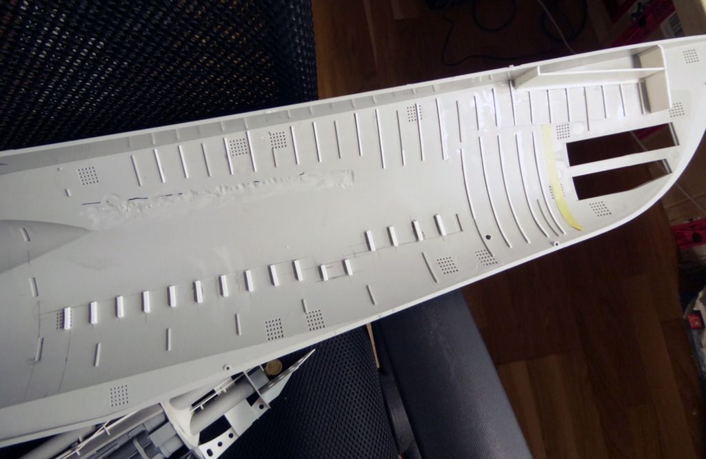
The hull got the internal ribbing. Slim ones for the wet part, and thick ones for the interior of the pressure hull.
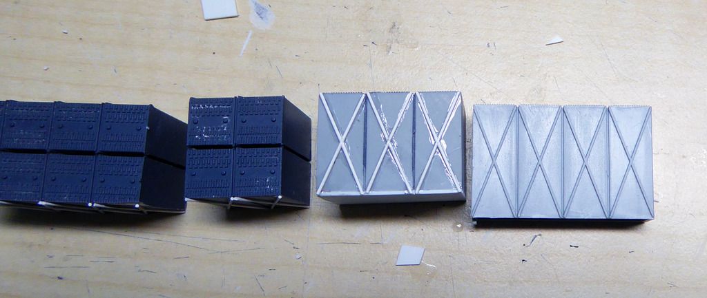
I also started working on the next room and found a first problem. The battery arrangement is wrong. To fix this, I had to cut the battery cells about 4 mm short - now they are correct. To add the missing cells, I'll make a silicone mould and cast the needed cells in resin.
Comment
-
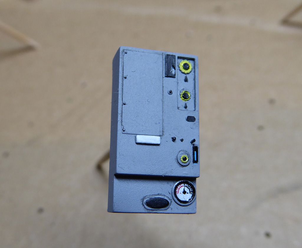
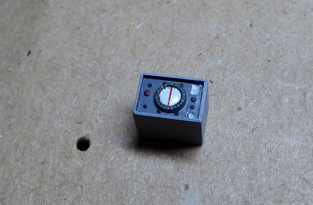
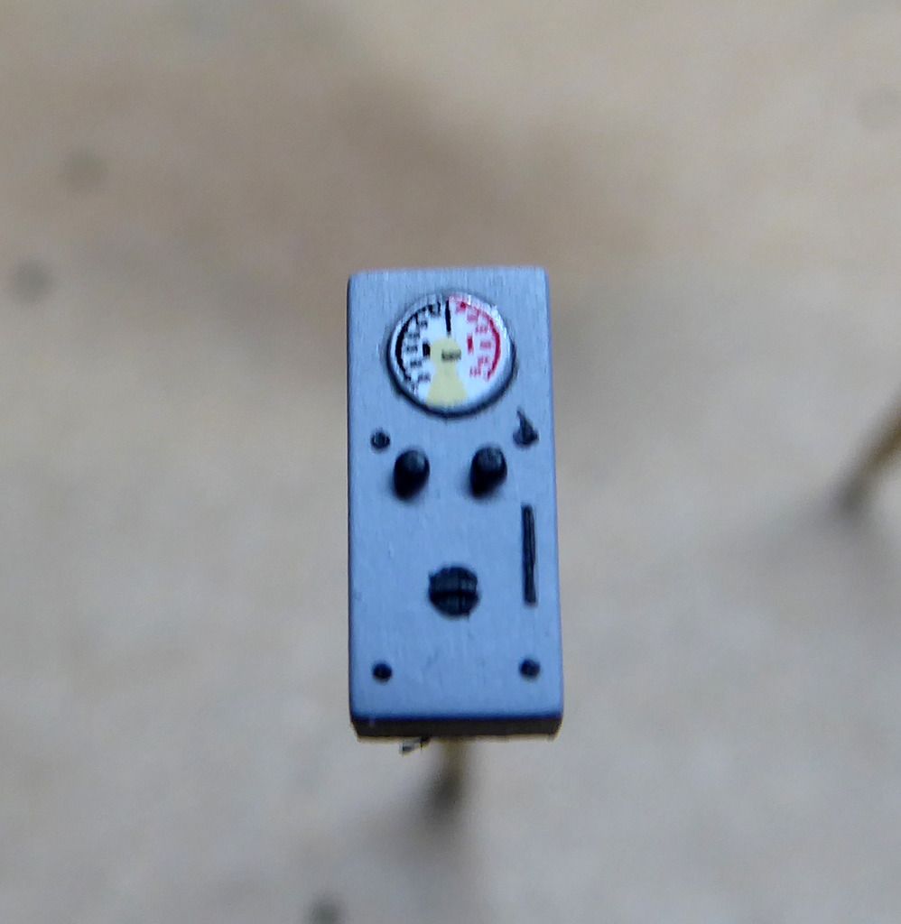
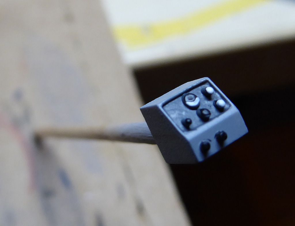
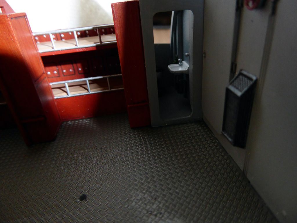
Working on the officers room which alo holds the sonar room, a toilet, and the radio room. It's pretty straight forward, but it requires allot of painting wood panels.
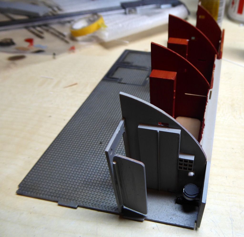
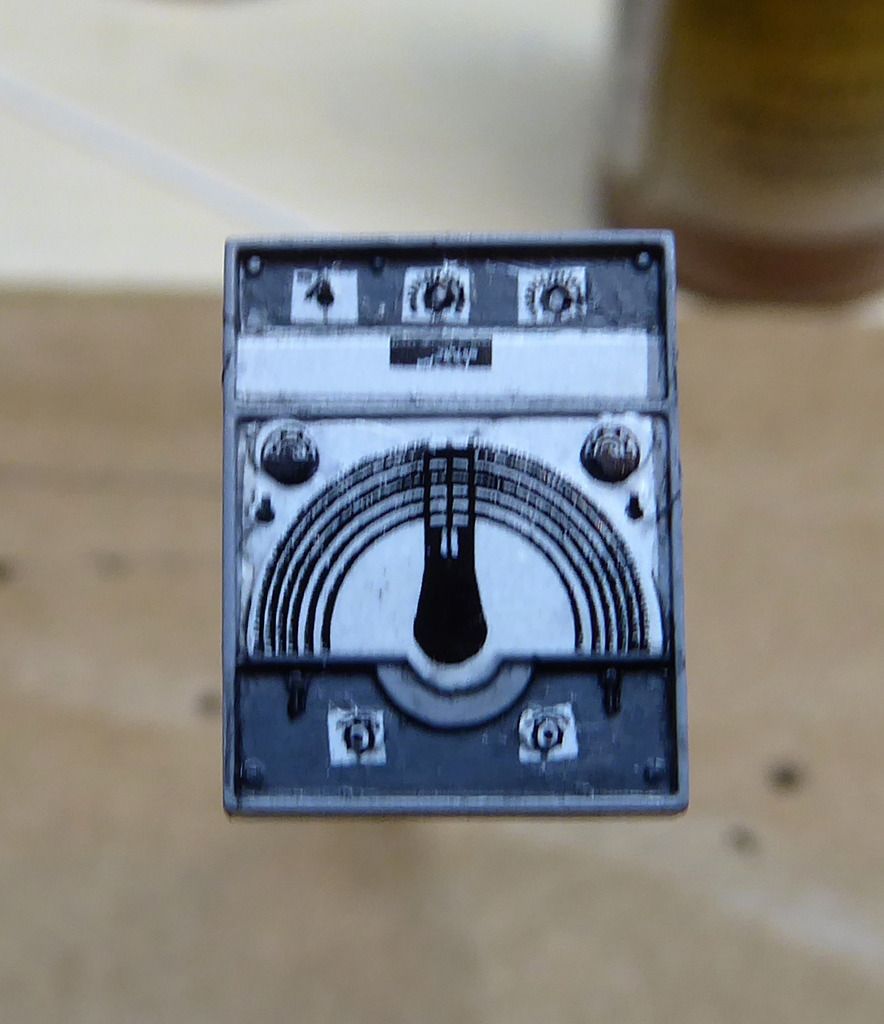
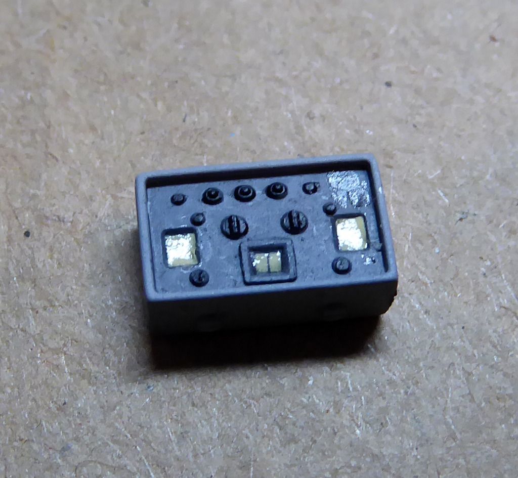
A side wall of the sonar room with the GHG console:
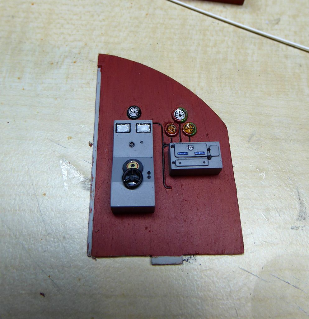
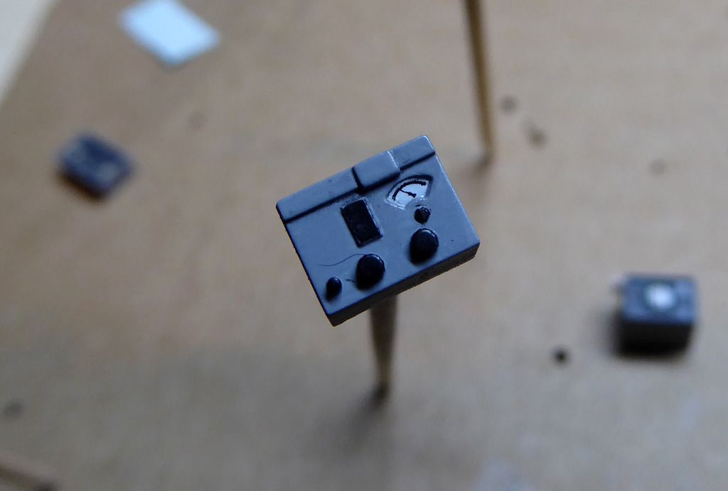
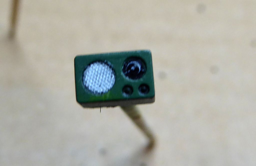
And tons of tiny boxes with allot of knobs and indicators. Ideal for training a steady hand....
Comment
-
was wondering where you'd run off too...
nice (delicate and tiny) work.Comment
-
Wood painting and the details take time. And I'm reworking the battery compartment below the officers room. Takes time as well.....Comment
-
no worries....and definitely not being pushy. it's great to follow along on this build.Originally posted by drschmidt View PostComment
-
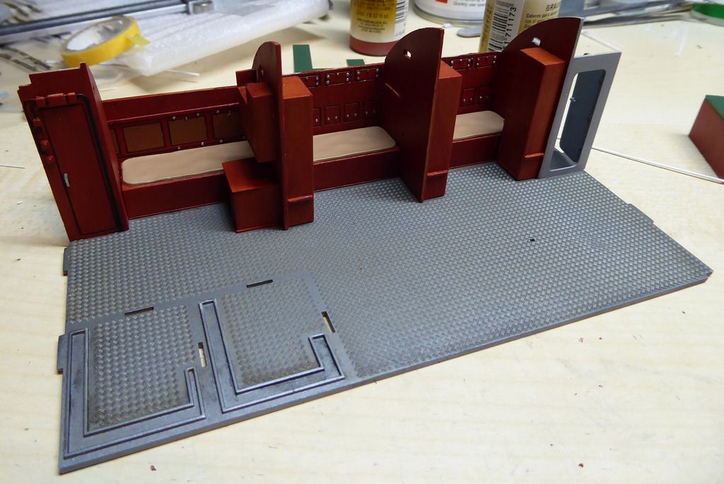
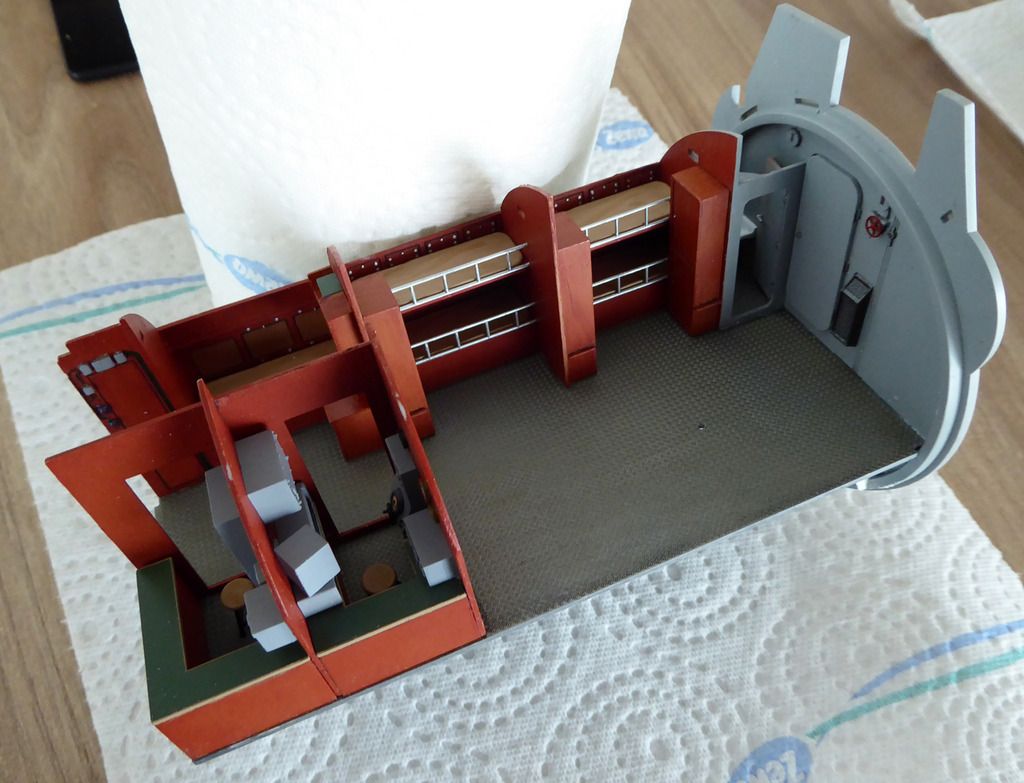
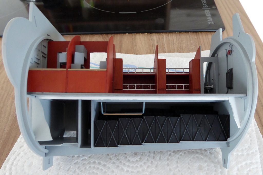
Continuing with the build of the officers' room. The beds, the sonar, and the radio room are assembled.
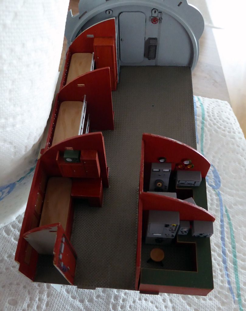
Under room for the crew is the forward battery room, the ammo storage, waste and fresh water tanks and all that surrounded by the forward oil bunker. The battery setup in the kit is wrong and incomplete. I shortened the battery cells and cast additional ones from resin for the back rows of cells. Then tedious painting......

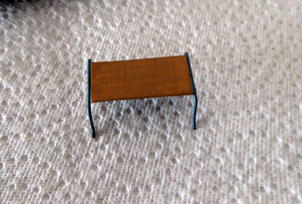
I also made the battery service sled from brass wire and styrene sheet.
I also changed allot with respect to the structure of the battery room. The ceiling got two rail for the service sled. The back wall is the inner wall of the oil bunker, that surrounds the battery room. The rectangular structure in the lower left is the waste water tank.
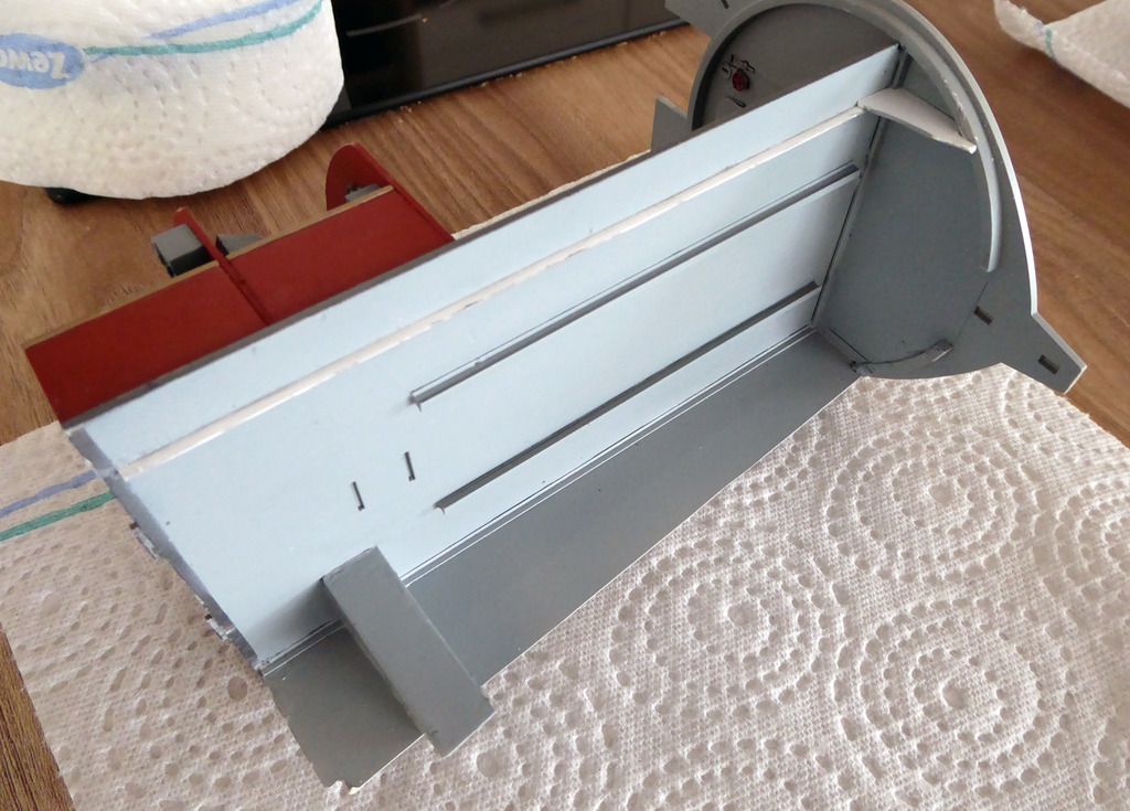
And I'm quite pleased with the look of the assembled piece:
Comment

Comment