
Part-11
I assembled this NAUTILUS kit as a ‘wet-hull’ type r/c model submarine. The hull and sail are free-flooding and the only spaces aboard that are dry are those two compartments at either end of a removable cylinder. This water tight cylinder (WTC) -- also referred in Europe as a ‘module’ ... or, ‘Tupperware’ when they’re in a particularly mischievous frame of mind -- contains the three basic sub-systems needed to animate the model submarine, endowing it with the ability to cruise either on the surface or submerged. Propulsion, control, and ballast.
Pushing out ballast water is done either by water pump, air-pump, piston, an onboard gas, or a combination of methods.
The removable cylinder concept has been around since the 60’s and commercial product since the late 80’s.
(For the Record: In the States credit for the design and continued development of the WTC is mine. In Europe I believe the lion’s share of credit for what they call a module goes to Brittan’s Nick Berge – one of the most prolific and out-of-the-box thinkers this hobby has ever had. In the days before the internet Nick and I worked toward development and promotion of similar systems, initially we were not aware of the others similar work).
Typically a WTC is divided into three sections, partitioned by four bulkheads -- one at each end, and two near the center of the cylinder. Between the two internal bulkheads is formed the WTC’s ballast tank. There are variations on this theme. The work of Ron Perrott http://www.rcsubs.co.uk/ and Norbert Bruggen come to mind, but for brevities sake I will focus specifically on the 3” diameter, two-motor-two-shaft SAS type SD worked up for the 1/87 USS NAUTILUS kit – the subject of this rather comprehensive WIP.
Most WTC’s differ as to materials and method of ballast water management. The WTC is an old idea: I have a picture of what otherwise looks to be a current version of a clear cylinder WTC from an old issue of Model Boats dated 1967. However, its cylinder was formed from Acrylic plastic – a material prone to cracking and difficult to machine. Today most clear cylinders are formed from Lexan, the same tough clear plastic used for soft-drink bottles and clear r/c car bodies.
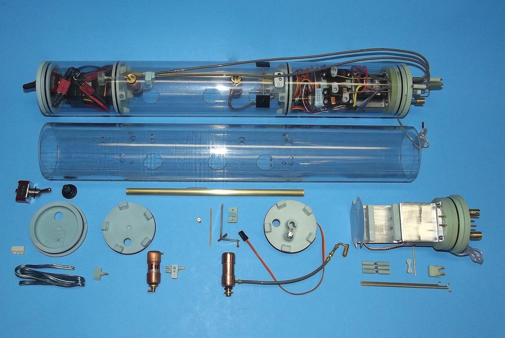
And here we have the WTC ‘system’ – a self-contained, removable, easily accessed water tight cylinder that contains the three sub-systems needed to effectively animate an r/c submarine: propulsion, control, and water ballast.
Atop is an assembled, outfitted, tested, and operational SubDriver (the proprietary name given our extensive line of WTC’s). These two sized and arranged specifically for the 1/87 scale USS NAUTILUS. Pictured are the significant components that go into the manufacture of this SubDriver (SD).
Four cast resin bulkheads divide the Lexan cylinder into three sections. The after dry section contains the propulsion and control elements; the center section forms the ballast tank; and the forward dry space houses the battery and mission switch.
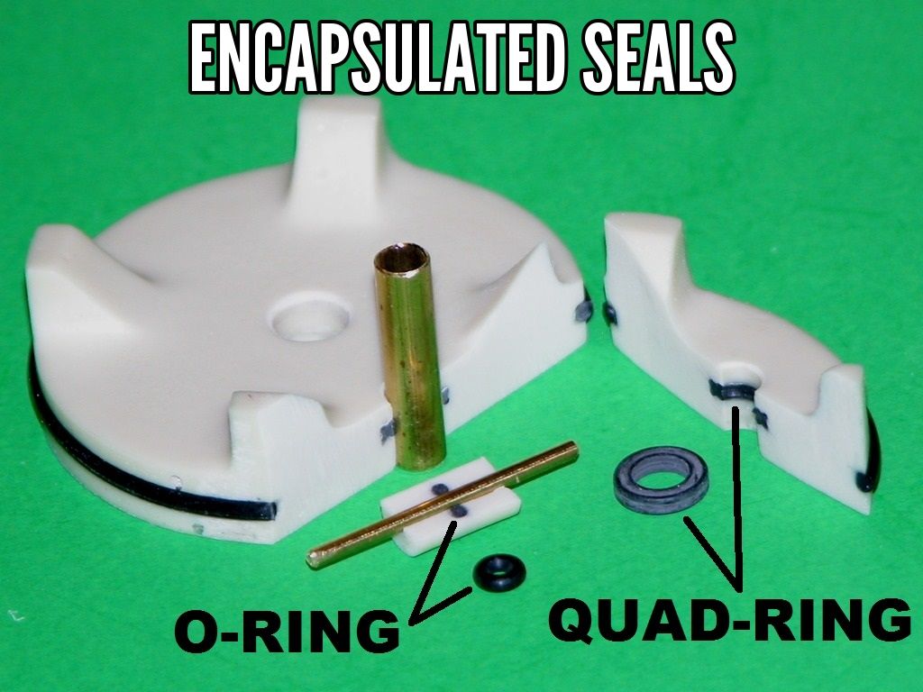
Examine the above cut-away examples of a typical WTC bulkhead and pushrod watertight seal to get an idea how the conduit, bulkhead, and pushrods are made watertight to the SD.
All four resin bulkheads are made watertight to the cylinder through edge sealing O-rings. The conduit -- a brass tube that running the length of the ballast tank -- is made watertight to the ballast bulkheads via partially encapsulated O-rings during bulkhead manufacture.
The pushrod watertight seals are descrete items that are RTV’ed into holes punched through the motor and after ballast bulkheads. Each pushrod seal features a 1/16” diameter bore with an encasulated O-ring at the seal bodies center which effects the watertight seal between its axial running pushrod and SD proper. The three pushrods that project aft make up to the stern plane, rudder, and bow plane linkages – all of which are external of the SD and make up with
magnetic connectors. A single pushrod passes between the dry and wet side of the after ballast bulkhead and is part of the linkage that controls the operation of the ballast tank vent and emergency gas blow valve.
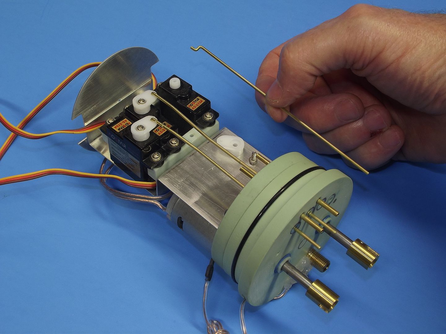
Three servos are mounted on the motor-bulkhead device tray. The one about to be made up to its 1/16” diameter brass pushrod drives the stern planes. This servo is tended by the ADF2 angle-keeper circuit (with operator input always available); the middle servo is for the rudders; and the port servo operates the bow planes.
Each servo pushrod goes through a watertight seal set into the motor-bulkhead. Those seal bodies made fast with RTV adhesive – this permits easy replacement if called for.
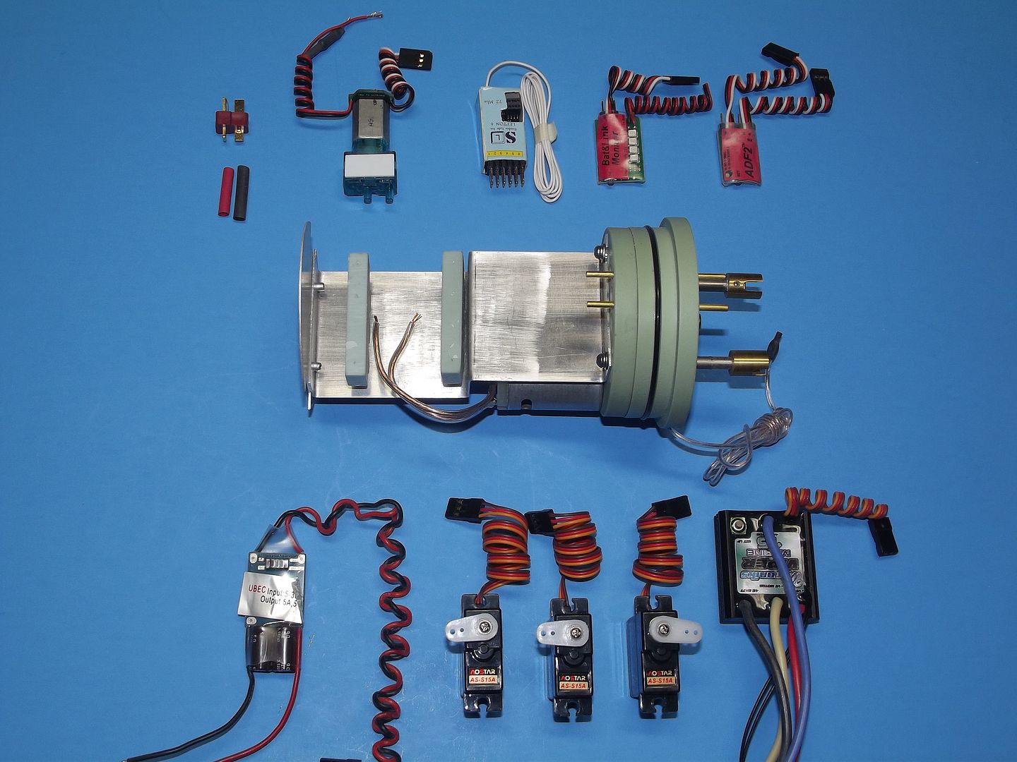
Like cramming ten-pounds of stuff into a five-pound bag!
That’s always been the situation with r/c model submarines. As illustrated here. All the devices that have to fit, coherently, onto the motor-bulkhead device tray and bulkhead can now be fit into a very tight package. Only with the development of small footprint devices (computer assisted circuit design and surface mount technology) and very selective receivers (signal processing in addition to detection) has this magic-trick been possible. Device size and receiver selectivity has been a boon to this hobby.
Pull the motor-bulkhead away from the cylinder and there are only two electrical connections to break to free the entire unit from the system: one pair of plug connectors interface the motor-bulkhead to the battery power cable, and the lead going to the ballast servo mounted to the dry-side of the after ballast bulkhead.
In order to better describe the function and arrangement of three sub-systems, I’ll discuss each in some detail with supporting pictures:
PROPULSION SUB-SYSTEM
The devices regarded as belonging to the propulsion sub-system include the battery, Electronic Speed Controller (ESC), mission switch, battery cable, battery, cable plugs, motors, motor spark- suppression, gear reduction and propulsion shaft seals.
BATTERY This particular SD is sized to fit the 1/87 USS NAUTILUS kit. As I found the size of the ballast tank left little room for both the forward and after dry spaces, this necessitated the use of ‘short’ 11.1-volt Lithium-polymer batteries. Two of these short batteries, wired in parallel, achieved the 3-Ampere hour capacity needed to keep the model running for a few hours between charges. Note the use of a three-plug adapter used to gang the two batteries together in parallel, permitting me to retain the original battery discharge plugs. One of these ganged batteries made up to the foreground

motor-bulkhead devices through a test/set-up power cable – this cable making set-up of the installed devices an easy matter, and is a perfect analog to the one that runs through the SD’s conduit tube.
ESC The electronic speed controller is a common, commercially available item that directs battery current of the desired polarity and intensity to the motor(s) as commanded by the transmitters throttle stick. I’m a big fan of the Mtroniks brand of brushed motor ESC’s. These units are waterproof, robust, and easy to program, and feature a relatively small footprint for the work they do. It’s a good practice to select an ESC with a maximum sustained current draw that approximates 2X the stall current of the motor(s) it’s connected to. For this application, where I’m driving two motors in parallel, I’ve found the fifteen-Ampere Mtroniks ESC to be more than adequate to the task. Though provided, you do not use the ESC’s battery eliminator circuit on the larger SD’s – it simply does not have the current capacity to meet the load presented to the receiver power bus. Either snip off or pull clear of the ESC’s lead the red wire to disable the ESC’s BEC .... NOT THE BLUE WIRE, OR WE ALL DIE IN A HORRIBLE EXPLOSION (for you WW-2 movie fans out there).

I assembled this NAUTILUS kit as a ‘wet-hull’ type r/c model submarine. The hull and sail are free-flooding and the only spaces aboard that are dry are those two compartments at either end of a removable cylinder. This water tight cylinder (WTC) -- also referred in Europe as a ‘module’ ... or, ‘Tupperware’ when they’re in a particularly mischievous frame of mind -- contains the three basic sub-systems needed to animate the model submarine, endowing it with the ability to cruise either on the surface or submerged. Propulsion, control, and ballast.
Pushing out ballast water is done either by water pump, air-pump, piston, an onboard gas, or a combination of methods.
The removable cylinder concept has been around since the 60’s and commercial product since the late 80’s.
(For the Record: In the States credit for the design and continued development of the WTC is mine. In Europe I believe the lion’s share of credit for what they call a module goes to Brittan’s Nick Berge – one of the most prolific and out-of-the-box thinkers this hobby has ever had. In the days before the internet Nick and I worked toward development and promotion of similar systems, initially we were not aware of the others similar work).
Typically a WTC is divided into three sections, partitioned by four bulkheads -- one at each end, and two near the center of the cylinder. Between the two internal bulkheads is formed the WTC’s ballast tank. There are variations on this theme. The work of Ron Perrott http://www.rcsubs.co.uk/ and Norbert Bruggen come to mind, but for brevities sake I will focus specifically on the 3” diameter, two-motor-two-shaft SAS type SD worked up for the 1/87 USS NAUTILUS kit – the subject of this rather comprehensive WIP.
Most WTC’s differ as to materials and method of ballast water management. The WTC is an old idea: I have a picture of what otherwise looks to be a current version of a clear cylinder WTC from an old issue of Model Boats dated 1967. However, its cylinder was formed from Acrylic plastic – a material prone to cracking and difficult to machine. Today most clear cylinders are formed from Lexan, the same tough clear plastic used for soft-drink bottles and clear r/c car bodies.


And here we have the WTC ‘system’ – a self-contained, removable, easily accessed water tight cylinder that contains the three sub-systems needed to effectively animate an r/c submarine: propulsion, control, and water ballast.
Atop is an assembled, outfitted, tested, and operational SubDriver (the proprietary name given our extensive line of WTC’s). These two sized and arranged specifically for the 1/87 scale USS NAUTILUS. Pictured are the significant components that go into the manufacture of this SubDriver (SD).
Four cast resin bulkheads divide the Lexan cylinder into three sections. The after dry section contains the propulsion and control elements; the center section forms the ballast tank; and the forward dry space houses the battery and mission switch.


Examine the above cut-away examples of a typical WTC bulkhead and pushrod watertight seal to get an idea how the conduit, bulkhead, and pushrods are made watertight to the SD.
All four resin bulkheads are made watertight to the cylinder through edge sealing O-rings. The conduit -- a brass tube that running the length of the ballast tank -- is made watertight to the ballast bulkheads via partially encapsulated O-rings during bulkhead manufacture.
The pushrod watertight seals are descrete items that are RTV’ed into holes punched through the motor and after ballast bulkheads. Each pushrod seal features a 1/16” diameter bore with an encasulated O-ring at the seal bodies center which effects the watertight seal between its axial running pushrod and SD proper. The three pushrods that project aft make up to the stern plane, rudder, and bow plane linkages – all of which are external of the SD and make up with
magnetic connectors. A single pushrod passes between the dry and wet side of the after ballast bulkhead and is part of the linkage that controls the operation of the ballast tank vent and emergency gas blow valve.


Three servos are mounted on the motor-bulkhead device tray. The one about to be made up to its 1/16” diameter brass pushrod drives the stern planes. This servo is tended by the ADF2 angle-keeper circuit (with operator input always available); the middle servo is for the rudders; and the port servo operates the bow planes.
Each servo pushrod goes through a watertight seal set into the motor-bulkhead. Those seal bodies made fast with RTV adhesive – this permits easy replacement if called for.


Like cramming ten-pounds of stuff into a five-pound bag!
That’s always been the situation with r/c model submarines. As illustrated here. All the devices that have to fit, coherently, onto the motor-bulkhead device tray and bulkhead can now be fit into a very tight package. Only with the development of small footprint devices (computer assisted circuit design and surface mount technology) and very selective receivers (signal processing in addition to detection) has this magic-trick been possible. Device size and receiver selectivity has been a boon to this hobby.
Pull the motor-bulkhead away from the cylinder and there are only two electrical connections to break to free the entire unit from the system: one pair of plug connectors interface the motor-bulkhead to the battery power cable, and the lead going to the ballast servo mounted to the dry-side of the after ballast bulkhead.
In order to better describe the function and arrangement of three sub-systems, I’ll discuss each in some detail with supporting pictures:
PROPULSION SUB-SYSTEM
The devices regarded as belonging to the propulsion sub-system include the battery, Electronic Speed Controller (ESC), mission switch, battery cable, battery, cable plugs, motors, motor spark- suppression, gear reduction and propulsion shaft seals.

BATTERY This particular SD is sized to fit the 1/87 USS NAUTILUS kit. As I found the size of the ballast tank left little room for both the forward and after dry spaces, this necessitated the use of ‘short’ 11.1-volt Lithium-polymer batteries. Two of these short batteries, wired in parallel, achieved the 3-Ampere hour capacity needed to keep the model running for a few hours between charges. Note the use of a three-plug adapter used to gang the two batteries together in parallel, permitting me to retain the original battery discharge plugs. One of these ganged batteries made up to the foreground

motor-bulkhead devices through a test/set-up power cable – this cable making set-up of the installed devices an easy matter, and is a perfect analog to the one that runs through the SD’s conduit tube.
ESC The electronic speed controller is a common, commercially available item that directs battery current of the desired polarity and intensity to the motor(s) as commanded by the transmitters throttle stick. I’m a big fan of the Mtroniks brand of brushed motor ESC’s. These units are waterproof, robust, and easy to program, and feature a relatively small footprint for the work they do. It’s a good practice to select an ESC with a maximum sustained current draw that approximates 2X the stall current of the motor(s) it’s connected to. For this application, where I’m driving two motors in parallel, I’ve found the fifteen-Ampere Mtroniks ESC to be more than adequate to the task. Though provided, you do not use the ESC’s battery eliminator circuit on the larger SD’s – it simply does not have the current capacity to meet the load presented to the receiver power bus. Either snip off or pull clear of the ESC’s lead the red wire to disable the ESC’s BEC .... NOT THE BLUE WIRE, OR WE ALL DIE IN A HORRIBLE EXPLOSION (for you WW-2 movie fans out there).


Comment