New project

Collapse
X
 
  • Time
  • Show
Clear All
new posts
  • QuarterMaster
    No one
    • Jul 2003
    • 607

    #226
    Very late in the thread......

    Iconic boat, beautiful builds.

    Wow, even a picture of Ellie included in one of that crusty "Torpedoman's" build photo's always brings it home for me with a bit of nostalgia...........

    So with my very own NAUTILUS is on it's way from the DeBoer EB Yards out of South Dakota , I of course paid close attention to this thread gathering all the research information I could. Sounds like I need a set of Jim's talked about blueprints as well...source anyone?

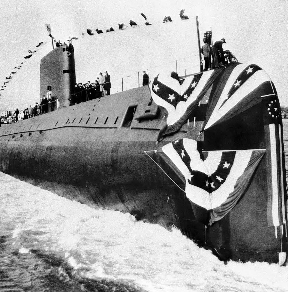
    I must say what stood out the most was the back and forth regarding her bow planes, which sent me off on a 6 hour tour of the 'net looking for the definitive proof of the rig for dive mechanics of the NAUTILUS bow planes.
    Don't get me wrong, it's just a very small point in an absolute stunning build, gorgeous attention to detail. Far exceeding my own "just get it to be able to come back" approach.

    But the Engineer in me wouldn't let it go.

    Funny how that little itch can make you beat the horse long after the bones became powder.

    So after a brilliant insight, I decided to get the answer from the horses mouth. Who can be a better source than an actual Submariner who Qualified aboard the NAUTILUS? As a former bubblehead, I understand what it means to be "Qualified in Submarines". We know our boats in and out, as good as the Engineers who designed them, who couldn't be there when a casualty hit and you needed to know EXACTLY what to do.

    So I reached out to Rick Turner, President of the NAUTILUS Alumni Association, who served aboard her from '66-'67. Interestingly enough, he never knew large RC Submarines existed, much less our organization or even running true to scale NAUTILUS models.

    His answer surprised me, but not for what you think.

    In the end it seems BOTH camps are right, but for the wrong reasons.......

    Hi Ed,

    Thanks for your wonderful email. I must say that I was unaware of submarine models that big let alone be operational. I think I recall playing with a model of Nautilus when I was a kid that used baking soda to submerge and surface. Your hobby sounds very interesting although expensive.

    It's interesting that your question concerning the bow planes has been posed before, so that means it's been researched and I have the answer. Initially the planes went fully horizontal, but during sea trials the planes caused a bad vibration throughout the boat. The vibrations went away when they were raised 30 degrees, so they put a stop in the system to prevent the vibrations.

    The Nautilus Alumni have a reunion every other year with every other reunion held in the Groton area so we can go see our boat again. This year's reunion will be held in Mystic September 25-28. When we don't return to Groton, our gatherings are held wherever. 2014 was in Cleveland and 2010 was in Pigeon Forge, TN.

    If you have any other questions, please feel free to contact me.

    Fraternally,

    Rick Turner
    Nautilus Alumni Association President


    Vibration causes transients, transients BAD.

    Silence, the Submariners shield, was the driving factor. Not hull interference or performance loss.

    Nice to make a connection with another group, may get new members out of it. It's always nice to correspond with people who've "been there".

    In the end, I'm eternally grateful to all of you that take the time to document and post your builds, techniques, research material etc along with all the back and forth, arguments and agreements.

    All good stuff.

    In the end, how will I rig my bow planes? Not sure until I do. At least I have a choice.

    Yeah, I had a baking soda NAUTILUS too..

    Keep it coming.
    v/r "Sub" Ed

    Silent Service "Cold War" Veteran (The good years!)
    NEVER underestimate the power of a Sailor who served aboard a submarine.
    USS ULYSSES S GRANT-USS SHARK-USS NAUTILUS-USS KEY WEST-USS KRAKEN-USS PATRICK HENRY-HMS VENGEANCE-U25-SSRN SEAVIEW-PROTEUS-NAUTILUS

    Comment

    • drschmidt
      Member
      • Jul 2014
      • 424

      #227
      HA, that's great. Thanks for digging out this information. I was aware of the vibration issue during trials. They nearly lost their bow. But I didn't know that the bow planes were the cause. So 30 degrees up means perpendicular to the 60° tilted hull.....I'm spot on.

      Nevertheless: The pictures from which I took my bow plane designs make clear that if the planes would be horizontal, they would collide with the superstructure. So my guess is, that when they put in the 30° stop, they also altered the bow planes to have as little as a gap possible between plane and hull. I know the planes were modified, as the bearing of the push rods got a housing, that wasn't there in the as built boat.

      Original Planes:


      Today:

      Comment

      • QuarterMaster
        No one
        • Jul 2003
        • 607

        #228
        My honor. Hopefully we get more exposure too!!

        Well, I plan a late model boat, so I'll join the 30 deg up club lol! Just getting a working deployment mechanism will be a first for me as all my previous builds had fairwater planes

        So much history on this boat, lot's of details to choose from!!

        The detail you and others here apply is something to behold on a models that actually submerge and gets banged around. All the bottom scraping on my GRANT lol!!

        Like I said in my earlier post regarding my priority, just bringing one in after a successful last surface at the lake is MY greatest joy.

        Ask any of these boat drivers here who sailed with me, they helped pick the bugs from my teeth from all the smiling on the way home.
        v/r "Sub" Ed

        Silent Service "Cold War" Veteran (The good years!)
        NEVER underestimate the power of a Sailor who served aboard a submarine.
        USS ULYSSES S GRANT-USS SHARK-USS NAUTILUS-USS KEY WEST-USS KRAKEN-USS PATRICK HENRY-HMS VENGEANCE-U25-SSRN SEAVIEW-PROTEUS-NAUTILUS

        Comment

        • drschmidt
          Member
          • Jul 2014
          • 424

          #229
          Hi Ed,

          excellent.....actually I like the strange look of the tilded bow planes.

          I count on you posting a WIP about your Nautilus build.

          Cheers Andreas

          Comment

          • QuarterMaster
            No one
            • Jul 2003
            • 607

            #230
            Andreas,

            Will do, from box opening to water. But before I let this go, got a couple of questions for you.

            I'm down the wet hull route, like Mr Merriman, but with my own scratch built WTC's. I run 12V SLA batteries by choice.

            Do you have any performance characters yet on how she runs? Specifically with respect to your selection of the Robbe ROXXY BL-Outr. (500kv) 4989.

            Also, very interested in the low end (where we tend to mostly run at) understanding these are 14 pole motors.

            For that matter, what processes lead you to selection of these motors? Considering length/weight/prop dia and run time.

            Any idea regarding shaft output in Watts?

            I'm new to brushless, very new and I'm looking at these for mine. I ordered one to do some testing on dynamic test stand I'm finishing up.

            Quanum MT Series 3510 630KV Brushless Multirotor Motor Built by DYS (Outrunner)
            Specs:
            KV(RPM/V): 630KV
            Lipo cells: 3-6S
            Max Power: 568.3W
            Max Amps: 25.6A
            No Load Current: 0.8/22.2V
            Internal Resistance: 0.59ohm
            Number of Poles: 14
            Dimensions(Dia.xL): 41.8*27.7mm
            Motor Shaft: 4mm
            prop shaft: 6mm CW prop adapter
            Weight: 100g
            bolt hole spacing: 25*25 M3
            Lamination thickness: 0.2mm
            Magnets: 42SH
            Wire: 18AWG
            Connector: 3.5mm bullet

            I'm thinking I may be overdoing it, but I'll see once I get it and the prop on the test stand.

            Thoughts?
            v/r "Sub" Ed

            Silent Service "Cold War" Veteran (The good years!)
            NEVER underestimate the power of a Sailor who served aboard a submarine.
            USS ULYSSES S GRANT-USS SHARK-USS NAUTILUS-USS KEY WEST-USS KRAKEN-USS PATRICK HENRY-HMS VENGEANCE-U25-SSRN SEAVIEW-PROTEUS-NAUTILUS

            Comment

            • drschmidt
              Member
              • Jul 2014
              • 424

              #231
              Oh, I was very pragmatic choosing the motrors: For my large U-1 (180cm length) I chose these motors because this setup is built into an Engel VIIc, wchich has about the same size and weight. So I thought this will work for my boat, too. The motors have plenty of power for the big boat....

              For the Nautilus I chose the same motors because I know them, they fit into the model, and if thye are able to drive a large boat, they will have no problem with a smaler boat. The props for the Nautilus were designed by me. So I'll have to see how they chime together with the motors. Real test with the Nautilus are imminent...

              Comment

              • drschmidt
                Member
                • Jul 2014
                • 424

                #232
                Part-8
                A notable departure from the kit instructions was my inclusion of additional sub-structure re-enforcement cross-braces. These to provide a more sound support under the very flimsy photo-etched (PE) deck pieces.

                Though the kit supplied GRP transverse deck pieces served this function to a degree, I determined that there were not enough of them to do the job adequately. My fear is that I or some other idiot, while handling the model would accidently damage the very fragile PE deck, ruining it.

                So, better now to strengthen the deck sub-structure than to repair a painted and weathered model after the inevitable deck damage occurred.

                Concurrent with that I began the task of representing the clear deadlights at the leading edge of the sail. I could have painted these on with a gray or silver color later – that would have been the simple solution. However, nothing looks like clear windows like … well … clear windows!

                These windows which provided visibility from within the sail to the forward deck were used by watch standers while the submarine cruised around on the surface in rough weather. There were three levels of these deadlights – the lower two levels represented by blocks of clear acrylic sheet, and the top level, forward of the bridge, would differ in that its deadlights would be represented by a build-up of clear, 12-hour cure epoxy glue – employing a very neat process advocated by David Manley. More on that later.


                Though the kit provides transverse GRP deck supports, I believe that the very flimsy PE deck pieces will be subject to handling damage (pushed in by fat fingers!) if additional sub-structure bracing were not provided. That’s what you’re seeing here: .015” thick styrene sheet transverse deck braces being installed atop the superstructure. The position of these additional cross-braces fell under (and was hid by) a corresponding all-metal transverse section of the PE deck. Under normal lighting conditions these sub-structure braces will not be apparent through the open slots between simulated wood planks of the PE deck pieces.


                You can see how I’ve arranged the additional sub-structure cross-braces, each sitting under the transverse all-metal portion of the slotted PE deck pieces. Later, after most of the painting is done, the PE deck pieces will be secured atop the superstructure with RTV adhesive.

                Note how the top of each cross-brass has been outfitted with slots. These to permit the quick longitudinal movement of entrapped air bubbles so they can move about and find a vent hole in the deck so they can escape. Entrapped air within a wet-hull type r/c submarine is a major problem and one has to be ever mindful to provide for complete venting of the hull as it makes the transition from surfaced to submerged trim.


                Making me the liar, this flash photography does show the additional transverse sub-structure elements added to strengthen the fragile PE deck. However, in the real-world, you won’t see much past the slots of the deck. This trick of lighting does show how I’ve placed the additional cross-bracing under the transverse ‘solid’ portions of PE decking.

                I must comment again at my amazement at how well everything on this CAD designed and CNC and printed tooling of this kit insured all parts fit together almost perfectly-this thing literally falls together out of the box!


                A Machinist’s surface-gauge was used to scribe the upper and lower edges of the yet-to-be-established deadlights. A right-angle triangle was used to guide a scribe as I cut in the deadlight vertical edges. Such lay-out precession was needed for the bridge deadlight cut-outs, but was over-kill for the plugs of clear acrylic actually used to represent the clear faces of the lower platform deadlights.

                A holding fixture was cut from shelving stock and the sail screwed to it using the same fasteners and foundations that secure the sail atop the NAUTILUS’s hull.


                The ballast sub-system employs a float activated snorkel valve within the sail. It was necessary to establish the where the bottom of the mast foundation piece sat within the sail so the snorkel could be made so it would not project above that line. On the outside of the sail I marked where the bottom of the mast foundation piece terminated and designed the snorkel mechanism to occupy the space beneath.


                A trick that goes back at least a century is the use of clear plastic plugs, inserted into the portion of model where you want windows, and to then grind the outer surface of the plastic (usually acrylic) to conform to the outer contour of the model. Once the face of the clear part is ground and polished back to an optically clear item, the window frames are made by masking over where you want only clear areas to be, then paint, and remove the masking. That’s what’s going to happen here to the two lower platform deadlights.

                Deadlight is navy-speak for windows.

                Two ¼” thick pieces of acrylic sheet have been roughed out to approximate shape. Once set into the leading edge of the sail each is CA’ed in place, and ground, filed, sanded, and polished to conform to the curvature at the leading edge of the sail.

                The drill was used to rough out the individual open deadlight ports up where the bridge will go. Diamond files were used to refine the square openings. Later these openings will be filled with clear epoxy glue. More on that later.


                The solid acrylic pieces filed and polished to conform to the leading edge of the sail. The bridge open deadlight frames will later receive epoxy lenses. But, once it’s all masked out and painted you will be hard pressed to see the difference in materials and fabrication methodology between the three platform deadlights.

                I could not use the acrylic trick on the upper deadlights as there is little space between the deadlights and forward section of bridge well – a cast resin piece that will later


                The installed pieces of acrylic plastic within the two lower platform deadlight positions has been ground, filed, sanded, and polished to follow the contour of the sails leading edge.

                The slabs of acrylic plastic were fine for the two lower levels, but not for the bridge level as those deadlights had to be of a thickness little more than the thin GRP of the sail.


                When painting over masked clear parts you always want to go with the final color, from beginning to end. If you don’t, then the different colors (gray and/or red primer for example) will result in a disparity of color at the edges that denote transitions from clear to colored portion of the model.

                So, if the final color will be a dark, dark, gray (the case with this model), then that’s the only color you will shoot over the clear part masks. Once the deadlight masks are in place I’ll lay down the first of many layers of final color. Paint does not typically have the heavy fill ability of a thick primer, but multiple coats will eventually get the job done around the deadlights.


                The bridge level set of deadlights has yet to receive its clear lenses. The two lower platforms have had their individual deadlights (each set actually a single hunk of clear acrylic plastic) represented by pieces of masking tape followed by a coat of dark-gray paint. Here, with the masking removed, we see what appear to be closely spaced, deadlights along the two lower sail platforms.

                Comment

                • drschmidt
                  Member
                  • Jul 2014
                  • 424

                  #233
                  Part-9
                  A statically diving type submarine submerges by taking on water ballast (variable ballast). The weight of the ballast water equal in weight to the water displaced by those portions of the submarine formerly above the surface.
                  The more structure above the surfaced submarines waterline, the more ballast water needed to counter the buoyancy of those structures once they are immersed in water. Good design practice would have you make the ballast tank as small as possible for two reasons:
                  First, is to minimize the volume given over to the ballast tank itself, leaving room for other devices needed to animate the submarine.
                  And less ballast water to be shoved in and out means less energy expended to move that water. Usually, as in this design, the air in the ballast tank is simply vented to atmosphere, done by a servo – not much energy expended there. However, to empty the ballast tank of water an air-pump has to be run, and that means a drain on the battery and wear and tear on the pump controller, pump, and its motor. Also, as my SD also employ’s an emergency gas back-up ballast blow sub-system, there is the kinetic energy stored within an on-board bottle of liquefied propellant, that energy given up each time an ‘unscheduled’ emergency surfacing occurs. We want to husband the vessels energy reserves. So ...
                  ... Small ballast tank-- good; big ballast tank -- bad.

                  In a wet-hull type r/c submarine superstructure and sail wall thickness is the main driver of total above waterline displacement. Most of the appendages are solid cast items, and they too contribute to the total above waterline displacement.
                  This kit, designed and manufactured by a model aircraft guy – which makes him a GRP weight conscious fanatic -- has above waterline structures of very thin section. That’s why this r/c submarine kit, even though it represents a boat of high freeboard, requires a relatively small ballast tank.

                  (GRP and polyurethane resin have specific gravities close to 1, so in this game weight pretty much equals displacement).
                  Unfortunately, when I sized the ballast tank for this model, I still managed to wildly underestimate the total displacement of the above waterline portions of the surfaced model NAUTILUS. The first trimming trail with that SubDriver (SD for short, or for you old-school types, WTC) revealed that shortcoming immediately. Compelling me to build another SD with an enlarged ballast tank.
                  The SubDriver is a removable system comprising the propulsion, control, and ballast sub-systems that animate the model. I’ll outline the SD’s design, fabrication and functions in a later installment.


                  The two machine screws that hold the upper hull down upon the lower hull are accessed through holes drilled through the PE deck – one forward, one aft. Great care was taken to secure the deck pieces onto the drill press bed: any drill chatter would easily tear the thin brass piece to shreds. Also, long before I determined securing screw locations I found spots on the PE deck pieces that were solid, and not impossible to drill slotted portions.
                  And that’s the case here. Note that the forward upper hull securing screw access hole will run through the PE deck where the solid deck hatch rescue-bell seating foundation is.


                  With the basic submarine structure completed and the SD and other internals worked out, time came to install the fixed ballast weight and buoyant foam – all arranged to work with the variable ballast water to set the boats displacement for both surfaced and submerged trim.

                  The trick is to make the center of gravity and center of buoyancy well distanced vertically; and for these two collectives of force to shift longitudinally, in unison, as the boat makes its transitions between surfaced and submerged trim.
                  Experience tells me that a four-foot long wet-hull type r/c submarine requires at a minimum two pounds of fixed lead ballast weight as low in the hull as possible. Here I’ve broken out some ingots of lead for a trial installation of fixed ballast weight.
                  A single screwed submarine would need more fixed lead ballast to better counter the torque of the propeller. However, as this submarine has two counter-rotating propellers (net torque is zero), I could get away with two pounds worth.

                  Comment

                  • drschmidt
                    Member
                    • Jul 2014
                    • 424

                    #234
                    The USS NAUTILUS, in surface trim, has a very distinctive waterline: A high freeboard (distance from waterline to top of deck); the bow high, and the stern low. Unlike so many of the cold-war era American submarines, this conservatively designed -- first vessel to be nuclear powered -- submarine embodied many of the post-war, old-boat characteristics: hull form optimized for surface cruising; wide flat deck; and a high freeboard owing to its (by today’s standard) a significantly large amount of reserve buoyancy.
                    Before starting the trimming operation – a process, by trial-and-error of the amounts and location of fixed ballast weight and buoyant foam – I marked out onto the hull, with a wide Sharpie pen, the submarines surface trim waterline. The objective is to have the boat, with dry ballast tank, float at this waterline in surface trim; and, with a flooded ballast tank, to project only the top of the sail above the waters surface in submerged trim. The marking was laid down with the model rubber-banded to a flat work surface, pitched up the correct amount (that angle established by checking with a Machinist’s surface gauge as the bow was shimmed upward), and the waterline marking tool run around the model, laying down the waterline where it should go.


                    The first attempt to trim the boat revealed that I did not have enough ballast tank volume to get the boat up to the designed waterline once the tank was blown and emptied of water. From submerged trim I needed a weight of ballast water equal to the weight of water displaced by all the above waterline structures. Didn’t have it! Damn thing sat low in the water with the tank dry. The ballast tank was too small. Who was the dumb-ass who designed this system anyway?!.....
                    Nuts!


                    Nothing for it but to make a new SD with an enlarged ballast tank.
                    (Two, actually: one to replace my first attempt at the SD, and a second one for Andreas who’s putting together a wet-hull version of this kit back home in Germany)

                    The new SD features a ballast tank possessing 150% the volume of the first. Note that I retained the initial SD cylinder length by giving up space in the forward and after dry sections of the cylinder.
                    The aft dry section had excess space so that was easily given up to the forward section of ballast tank by moving the after ballast bulkhead aft a bit more. The forward dry section, containing the battery and mission switch was shortened by simply going to a shorter battery – cramming two of them in there and wiring them in parallel, giving the same capacity of the single long battery. The forward ballast bulkhead moved forward. Other than the bigger ballast tank and some minor relocation of ballast sub-system components, the length, function, and dry weight of the short and long ballast tank SD’s is identical.


                    Submerged trim is worked out first. The ballast tank is flooded. Once that’s set, you establish surfaced trim.
                    Yes, with all that foam hanging off the model it looks like hell.

                    Just the top of the sail projects above the water as the boat stabilizes at zero pitch and roll angles. Perfect submerged trim for a typical r/c model submarine equipped with a ballast tank. This is the condition of the submerged boat once the correct amount and location of buoyant foam has been established.

                    Working out foam amount and location to the outside of the hull is a lot easier than stuffing it within the hull and hoping you got it right. This way, the trimming is done in one, quick, sitting, without having to yank it out of the water numerous times.

                    “Are we done yet??!!!!”
Surface Trim, the ballast tank blown dry.
                    Some of the buoyant foam has been moved vertically, either above or below the surfaced waterline – the objective to get the boat to float at the designed waterline. There is more ballast tank volume than that needed using the new SD. That’s a good thing! The higher the center of buoyancy is over the center of gravity, the more statically stable becomes the vehicle.
                    Submerged and surface trim fixed, the model is taken back into the shop and all that foam is glued to the inside surfaces of the hull and superstructure.


                    The laborious process of shifting all that foam from the outside of the model to its inside has begun. It’s vital that the buoyant foam you select is of the closed-cell type. The blue and pink polystyrene expanded foam is of this type. Unlike open-cell type foam (usually white), the closed-cell type will not water-log over time. There is absolutely no need to ‘seal’ installed closed-cell type buoyant foam.
                    Here you see the installed fixed lead weights, and foam pieces ready to be installed within the hull. Note that some of the foam has already been shaped and bonded within the upper hull half.


                    The important thing is to get the longitudinal and vertical position of the foam correct. What was established during the trimming operation, placing the foam on the outside, now has to be replicated as the foam is glued to the inside of the model.

                    Comment

                    • drschmidt
                      Member
                      • Jul 2014
                      • 424

                      #235
                      Davids first run...my boat will get it's own today:

                      The first open-water run of the 1/87 USS NAUTILUS r/c submarine kit I acquired from Germany. Produced by Andreas Schmehl this is an easy to assemble and drive r/c submarine.

                      This outing presented in the following video was to establish surfaced and submerged turning radius. I find this to be a well running model submarine both on and under the surface. The initial run of this boat was in the rather confining boundaries of a local swimming pool which did not give me the opportunity to maneuver the model with any real freedom. However, that all changed when I went to some open water, as you can see in the video.

                      The model employs a Caswell-Merriman SubDriver -- the system that controls, propels, and manages ballast water. The system is removable and easy access to its devices through the two end bulkheads is quick, easy, and assured.

                      This SD, customized specifically for this r/c model submarine kit, will be available soon through the Caswell catalog.

                      I have posted the video to Youtube.


                      David

                      Comment

                      • drschmidt
                        Member
                        • Jul 2014
                        • 424

                        #236
                        Drove mine today. Fun ride all the way. Yes, it does need space to turn when surfaced, but it turns much better submerged. I actually ran it more under water than surfaced. I had good depth control even with fixed bow planes. The rear planes do a splendid job due to their position directly behind the propellers.

                        Only turn downs: Lost some paint on the lower hull due to some contact with rocks (the paint does not adhere very well...should have used an epoxy primer). And the drive battery seems to make trouble. Might just be the balancer cable.

                        But all in all: The best boat I built so far.

                        Comment

                        • drschmidt
                          Member
                          • Jul 2014
                          • 424

                          #237
                          This model kit WIP installment is exclusively dedicated to the NAUTILUS’ sail. And for good reason: Much as a scale model airplanes cockpit, the sail of a submarine model is the focal point of the viewer’s attention – the ‘front office’ of the vehicle; it’s where the machines intelligence and purpose are housed. The sail is where the people are. The sail also is one of the few places where you get a sense of the dynamic of the vehicle it represents: the optical and electronic sensors rising and descending upon their masts and faring; and It’s the last thing seen as the boat dives, and the first thing seen when it surfaces.

                          As a display, the sail is the most interesting aspect of the model. One must do it justice if the display is to be attractive and interesting. The model submarines sail is the focal point of the display, have no doubts about that.

                          The sail, with all those windows (deadlights); masts and fairings; antennas; periscopes; and open bridge with its deck, compass repeater, alarm boxes, platforms and such: all items that demand special care by the model kit assembler.


                          Since the earliest days of submarining the conning towers -- and fairings over those conning towers if used -- featured clear windows through which watch-standers could conn the boat, surfaced or submerged.

                          These windows, properly called deadlights, were quickly abandoned as pressure hull penetrations with the advent of the periscope. Deadlights of any significant size present a flooding hazard should the fragile glass lens fail as a consequence of collision or close aboard explosion. In any event, even with good underwater visibility, only on rare occasions could one see past the bow of the submarine – of little utility to the helmsman maneuvering the boat while submerged.

                          From the 30’s onward submarine deadlights were relegated to the free-flooding portions of the conning tower fairing where watch standers would seek refuge against the waves while navigating the boat on the surface.

                          Today, the use of sail mounted deadlights has been all but abandoned (The Russian Rubin design bureau being the last significant advocate). With the advent of nuclear power and AIP the imperative that a submarine ride out a storm on the surface was eliminated – no need for weather beaten watch standers to duck down to a protected platform and peer out through its deadlights. Today, if it’s rough, the boat submerges and everyone enjoys the ride beneath the waves – no longer must the watch standers take green water in the face while powers puking over the side as cold water streams down their backsides (I speak from grim experience!). God bless nuclear power!

                          DBF … my ass!

                          As built, the USS NAUTILUS featured no less than three levels within the leading edge of the sail outfitted with deadlights for outside observation. The bottom platform had three deadlights; the middle platform had five deadlights; and the bridge level platform had another five deadlights. That’s a lot of Plexiglas! The US Navy finally abandoning sail mounted platforms equipped with deadlights with the introduction of the THRESHER class submarine.


                          The kit provided sail-top represents the ‘armour’ bulged top aft of the bridge opening. This bulg afforded a few inches of protection over the tops of the retractable antennas, induction, and optical heads – an alteration of the origional flat sail top, prompted by the famous under-ice exploits of this world famous submarine.

                          However, my kit is being assembled to represent the ‘as launched’ boat, with the flat sail- top. I had to make a new sail-top.

                          I substituted a .031” thick piece of commercially available fiberglass sheet (G-10) for the kits sail-top. This very strong material is dimensionally stable, and takes to adhesives, primer and paint very well.

                          Note that the G-10 sail-top piece is temporarily held to the cast resin mast foundation piece with the aid of two machine screws (seen atop the sail-top between the masts and fairings). The ability to refine the shape and position of the many sail-top holes for wells, lookout stations, masts and fairings with the mast foundation piece out of the way makes those jobs a lot easier.


                          The kits cast resin mast foundation piece – used to both provide some of the housing wells and supports of the masts and some of the antennas atop them – had its sides milled down and a good portion of its bottom cut away to reduce total weight/displacement. This one piece, as it was, displaced nearly one- ounce. After the cut-down it displaced about a third of that. That’s a lot of weight removed from the tallest point on the model, aiding greatly in keeping the models center-of-gravity reasonably low. This weight reduction would minimize heeling in tight turns on the surface, and would contribute to better static stability about the roll axis.

                          Using the original resin sail-top piece as a template, I scribed onto the G-10 the sail outline as well as the shapes and locations of the holes for the bridge, lookout stations, antenna and optics retractable masts, and fairings. Those scribed lines highlighted by smearing some artist’s oil paint over the work.

                          Comment

                          • drschmidt
                            Member
                            • Jul 2014
                            • 424

                            #238
                            The G-10 was cut out on the band saw to outline; and the well, mast and fairing holes punched out and shaped with drills, burrs, and diamond-dust jeweler’s files.

                            The only two retractable masts not represented in the raised position on this model will be the communications UHF-VHF whip-antenna mast-fairings. The top of those ‘retracted’ mast-fairings represented as engraved tear-drop shaped forms scribed upon the sail-top piece.

                            An aluminum scribing stencil used here – the cutting done with two scratch-awls: a starting scriber with a sharp point, and a widening scriber with a blunt point to widen the engraved line. GRP material is very, very tough to scribe owing to the glass content which quickly dulls the steel tools, which required their sharpening several times during the course of this work.

                            As a great deal of force is applied to the scribe, both down into the work and against the inside edge of the stencil, it’s a good practice to glue the stencil in place during the entire cutting operation least the stencil shift, resulting in a ruined engraving. It’s easy enough, once the scribing is done, to pop the glued stencil off the work and scrap away any remaining adhesive from the work. On occasion I will even use machine or wood screws to hold a scribing stencil down securely onto the work.

                            Engraving is hard.

                            Filling and fairing over screw holes and scraping away glue is not.


                            While I was integrating the G-10 sail-top and cast resin foundation pieces I kept the two registered together with two machine screws that temporarily pulled the two pieces together. This permitted me to easily access both pieces, separately, as I cut out the holes for the masts through the G-10 sail-top, and worked to bore or sleeve the mast foundation piece bores to imperial sizes.

                            Damned metric-system! Can’t these people count to twelve!?....


                            As I stated before, big blocks of clear acrylic were employed to represent the transparent elements of the two lower platform deadlights. However, a different means of producing clear deadlights at the bridge level was required owing to the very small space between the inside surfaces of those deadlights and the front of the cast resin bridge piece.

                            I opened up the deadlight openings; each framed as on the prototype, and then touched the edges of these holes with a clear self-curing resin, such as epoxy glue. Now, if those openings were small enough (they were not), the strong surface-tension of the liquid would hold its form and it would bridge the entire opening as the application tool was slowly removed. The clear resin would be left to changes state from a liquid to a solid.

                            However, the larger openings, like these deadlights, require additional steps as the deadlight holes are way too big to be bridged in one glue application. Though it did not bridge the opening entirely, that first application of glue did build up a significant radius of clear adhesive at the deadlight corners and did build-up along the edges, reducing the amount of glue (and reducing the risk of introducing air-bubbles in later applications) needed to complete the bridging of the deadlight openings.

                            (You plastic model plane and ship guys may recall the ‘crystal-clear’ product for representing port holes and the like – a thick, clear-drying liquid that had the surface tension to hold form once applied with a round tool to the edges of a hole. When applied correctly the goo would hold as a film within the opening where it would be permitted to harden into a not-quiet optically clear transparency).

                            What David Manley taught me, and I replicated here, is to place a masking tape damn around the leading edge of the sail and apply glue from the inside, building it up thick enough to conform to the inner curvature of the sails leading edge – bridging all the deadlight openings. The outside mask insuring that the forward face of the clear glue assumed the curvature at the leading edge of the sail.

                            After the clear epoxy glue has cured hard the masking tape is pulled away from the sails leading edge, the inside and outside surfaces of the clear deadlights are filed, sanded, and then polished to the contours of the sail, inside and out. Deadlight masks were applied and the black (very, very dark gray) exterior painted.

                            Nothing to it!


                            It’s my practice to keep as many model assemblies separable as long as possible during the course of the job.

                            The entire sail assembly, only some of which you see here, is a case in point: the removable sail-top (secured to the to the sail during the in-water trimming operation and when there is a need to integrate pieces that need clearance between both sail-top and sail) permits easy access to the inside of the sail for SD snorkel mechanism integration and installation; work on the three platforms of leading edge deadlights; finish and detailing tasks to those inside surfaces of the sail seen through the open bridge and lookout stations; detailing ;installation of the sail-to-hull screw foundations; and the manufacture and fitting of the hand-rails that run both sides of the sail.


                            Another departure from the kit-as-provided was to make the forward ‘tub’ -- that forms the open bridge atop the sail -- removable. Accomplished by gluing four RenShape drilled and taped foundations: two to the bottom of the sail-top and two to the back of the bridge tub. Once the sail-top is glued permanently atop the sail I retain the ability to install/remove the bridge tub as required.

                            The two ‘L’-shaped brass items, each projecting from a side of the sail, are the mounts that interface the UHF-VHF whip antennas (represented by lengths of stretched sprue or cat whisker …. “here, kitty, kitty, kitty!”) with their respective ‘retractable’ fairing. A RenShape block glued to the bottom of the sail-top receives a whip antenna mount. Cut-outs in the sail-top and sides of the sail permitted each mount, with its attached antenna, to project well clear from the side of the sail.


                            The completely assembled sail-top being test fitted atop the sail. Note that all the deadlight work is done and that each deadlight has been masked and dark paint applied and the masking removed to reveal the correct number and size of deadlights that, on the real thing, permit crew observation from the three platforms within the sail – but only on the surface as the entire sail (except for the bridge hatch access tunnel) is free-flooding.

                            At this point the mast foundation piece will be glued to the bottom of the sail-top, the two temporary screws holding the two assemblies together removed, and their holed filled and faired over. The bridge tub will be unscrewed, removed, and set aside. And the sail-top permanently CA’ed atop the sail and the edge between sail-top and sail will be filed and sanded to the proper radius.

                            Comment

                            • bob_eissler
                              SubCommittee Member
                              • Aug 2005
                              • 340

                              #239
                              Beautiful work! I think we are all drooling over the build of this one. Are you going to be selling the Nautilus soon?

                              Comment

                              • drschmidt
                                Member
                                • Jul 2014
                                • 424

                                #240
                                Not sure if and when. I'm definitely doing a small round of dry-hull boats for Germany. Selling to the US is a major hassle......not sure if I'm going to venture into that territorry.

                                Comment

                                Working...