Revell typ VII/41 RCABS (Big Dave) build

Collapse
X
 
  • Filter
  • Time
  • Show
Clear All
new posts
  • Dolfin
    Junior Member
    • Jun 2020
    • 31

    #16
    Hallo,
    I’m using the RCABS not the RCABS-R System. About the seals I don’t know I hope I made it right otherwise there is a lot of work to do.
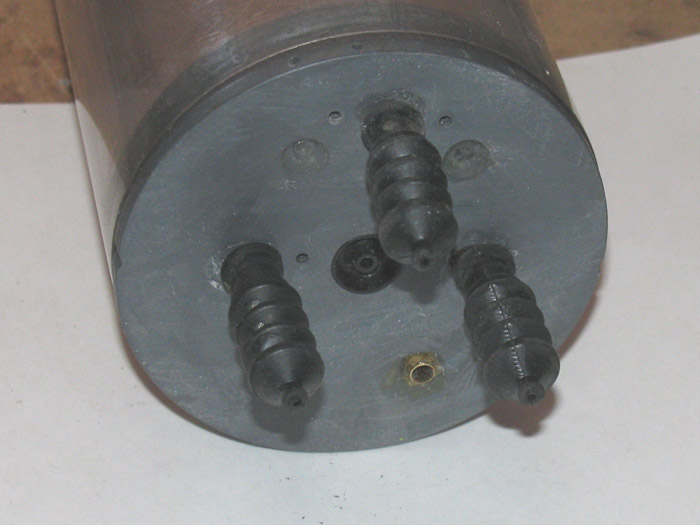
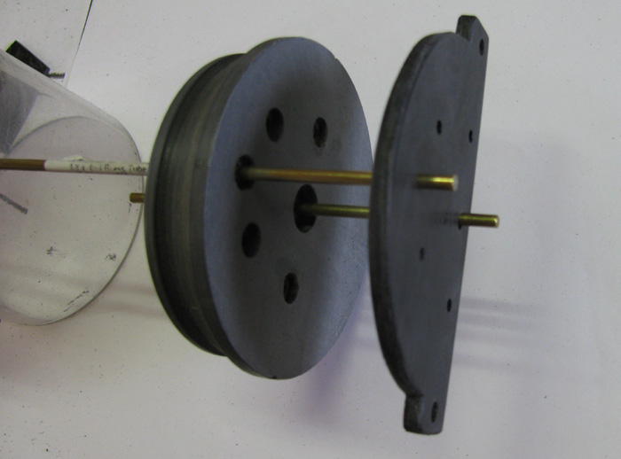
    I made it like so:
    Click image for larger version

Name:	EE009247-B5E2-4A6E-B533-06CBD1D0485C.jpg
Views:	1
Size:	9.0 KB
ID:	134757
    I thought I make two of them in opposite directions one against water and one against vacuum pressure.
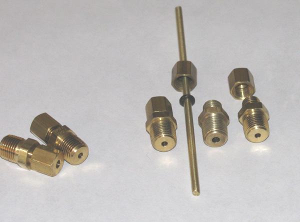
    Here is visibly the front and backside and the lip.
    Click image for larger version

Name:	D2EAFA77-2189-4244-8F89-9717F909A9D7.jpg
Views:	1
Size:	7.0 KB
ID:	134758

    What would Ralph say about that?

    ps. Is it possible to order something from frontiernet again?
    THANKS for helping

    Comment

    • Ralph --- SSBN 598
      Junior Member
      • Oct 2012
      • 1417

      #17
      What would I say?

      Well, I will say I try many different things.
      I have a 1/72 scale Skipjack I use as a test boat to try various things.
      It has gone through 4 different ballast systems and several modifications.
      Several types seals.

      About seals.
      I use cup seals for motors and I use either o-rings or boots for push rods.
      (I started with o-rings for the motor but found they got hot and started leaking.
      (this was before internet and being about to talk to other submarine builders)

      I put motor cup seals on the outside of the end cap with a cover plate to hold it in place.
      This end cap has boot seals for push rods.
      This is currently in the Skipjack. (3 maybe 4 years now)


      Here are o-ring seals with ferrule brass fittings.
      They can be adjusted to press down on the o-ring. (It does not take much)
      These where very heavy and required more cylinder ballast tank or foam to balance.


      I have made end caps with the cup seal and several o-ring seals embedded in the end cap with a cover palte tocompression.


      There are many ways to accomplish what you need done.
      Most work just fine.
      Some fail and are never to be seen again.
      Like trying to use stuffing tubes from surface power boats in submarines.
      They work for a while until the rotating motor shaft heats up the grease and then the water pressure pushs past the grease.

      Be carefull with the motor seals.
      Too much seal pressure on the shaft will cause the seal to over heat and the motor to over heat and use more current to make it run.

      The amount of water pressure at depth is not as much as some might think.
      Examples:
      5' = 2.17 psi
      10' = 4.34 psi
      16" = .56 psi (periscope depth for my Skipjack)

      NOte: I have got to like boot seals but they are fragile and need replacing often.
      The o-ring push rod seals seem to hold up the best with very liittle maintenance.
      They can be cleaned and grease once a season.
      Boots need inspection every time the rear capis removed.
      They get small cracks in the bellows folds that require flexing the boot to find.

      My opinion is o-rings are easier to install and maintain.
      They can be lighter in weight depending on the fitting or installation of the o-ring.
      And they are cheaper to buy. (just about any hardware store will have them in the faucet repair section)
      ============
      Just notice the part about 2 seals facing oposite directions.
      If a small leak should happen and get between the cup seals, the pressure will pop one or both of them out of the pocket.

      If you want to use 2 cup seals, they should face the same direction.
      The direction should be to keep water out.
      If the pressure becomes high in the cylinder, air will leak going out of the cylinder and still not let water in.

      Comment

      • Dolfin
        Junior Member
        • Jun 2020
        • 31

        #18
        Hallo Ralph,
        Thank you so much for perfect explanation and effort. I am very thankful for that the. I can turn one cup seal behind the motor or gear not a big deal.
        I can see in the first picture the cup seal is mounting with the open side in direction to the water. I now know how to install it correctly.
        Is it still possible to order from the Dave Welch shop.

        Best regards

        Comment

        • sam reichart
          Past President
          • Feb 2003
          • 1303

          #19
          Originally posted by Dolfin View Post
          Hallo Ralph,
          Thank you so much for perfect explanation and effort. I am very thankful for that the. I can turn one cup seal behind the motor or gear not a big deal.
          I can see in the first picture the cup seal is mounting with the open side in direction to the water. I now know how to install it correctly.
          Is it still possible to order from the Dave Welch shop.

          Best regards
          Big Dave passed away a few years ago. I don't know if anyone has parts for his systems.

          Comment

          • Ralph --- SSBN 598
            Junior Member
            • Oct 2012
            • 1417

            #20
            If you tell us what parts you need, maybe someone will have those parts, know where toget them or know what replacement will work.

            Tom is always saying, "There is more than one way to build submarines." ?
            Or something like that.
            Last edited by Ralph --- SSBN 598; 07-08-2020, 12:17 AM.

            Comment

            • redboat219
              Member
              • Jan 2005
              • 519

              #21
              RCABS- air from inside wtc gets pumped to bladder
              inflating it to surface the boat.

              REVERSE RCABS- air from pressurized tank inflates
              bladder to surface boat. To dive, a
              vacuum pump pulls air from the bladder
              back to the tank.

              Comment

              • Dolfin
                Junior Member
                • Jun 2020
                • 31

                #22
                @Sam Oh no that’s sad.
                @Ralph, that’s great at the moment I need no parts but sometimes are replacement parts necessary.
                My dog bones connectors are on the way then I continue building.
                Greetings

                Comment

                • Dolfin
                  Junior Member
                  • Jun 2020
                  • 31

                  #23
                  Hallo friends,
                  I hope you are doing well in the crazy time of pandemic. I need your help again, my Typ VII with the Big Dave’s kit is almost ready and working well. It took a lot of experience to learn needs more trimming now. I don't really like that I didn't reach the CWL correctly, which is about 3/8 " too deep.
                  I read that the last version v3 of Big Dave used two Bladders. Maybe who knows more about it from you and can tell me the layout and size of the bladders. I found a shop where I can order bladders in different sizes.
                  My 2nd question:
                  I noticed that when I inflated the bladder after a while (~ 5min or more) it was losing air. I checked the WTC for leaks but found nothing. WTC immersed in water with hose blown in, no visible bubbles.
                  Interesting why the bladder is without air again after a while but it doesn't matter I can easily pump up a bit when the boat is in the water.

                  I hope you can help me again Thank you and stay healthy.

                  Comment

                  • greg w
                    SubCommittee Member
                    • Mar 2010
                    • 350

                    #24
                    I believe that BD’s last version used two children’s “ punch balls” as bladders. They are basically heavy duty balloons. I have his type 7 and that is what was attached to the air line out of the etc. Greg

                    Comment

                    • greg w
                      SubCommittee Member
                      • Mar 2010
                      • 350

                      #25
                      here is a copy of his twin bladder instructions from my cd.


                      This is a bladder modification that will allow a lower waterline on my VIIc cylinder kit. I have found this to work very well in keeping the air lower in the hull which is essential to getting the max waterline.
                      The bladders basically occupy the space that the original VIIc had its saddle tanks. There is one bladder on each side which is made from Punch Balloons. These come four to a pack and are available at stores like Party City. The balloons that I used were made by Unique.
                      I used a section of 3/8” thick wall rubber tubing about 1.5” long. A short section of 5/32” K&S brass tubing about ½” long, and two tie wraps to add an input for the bladder. Slide the 5/32” tubing inside of the 3/8” rubber tubing and place that side with the brass tube in the mouth of the balloon. Fold over the mouth section around the rubber tube and add two tie wraps to seal the opening. Slightly inflate the balloon and check for leaks with water. If it is leaking just snug the tie wraps a little more. You will need two of these bladder assemblies, one for each side.
                      Now you will need the connector tee that connects the two bladders at the front of the ballast section. This is made from two sections of 1/8”K&S soft bendable brass tubing, and two short sections of 5/32” brass tubing. Make the tee fitting per the assembly drawing in the instructions.
                      How this tee assembly connects to the output of the cylinder will depend on the number of outputs in your cylinder. My cylinder has two outputs but some build it with only one.
                      On mine I made another small tee assembly to connect the two outputs together and then this single output will connect to the front bladder connection tee.
                      The last component of the modification is the cover plate that will keep the bladders form rising up into the upper area of the ballast section. This is made from .030 clear plastic sheet. Most all hobby shops sell it and mine was made by K&S. Cut the plate to the size shown on the drawing. This can be done with a good pair of scissors. The location and number of holes for the cylinder outputs will depend on how many and where they are on your cylinder.
                      This completes the making of the parts required. Now I will talk about how to install the system.
                      The installation is very easy. One of the bladders is placed on either side of the cylinder in the cove area made by the saddle tanks. Make sure they are down in the area as far as you can get them. I connect them to the front connection tee before I place them in the sub. Then the cover plate is inserted in the hull over the bladders and cylinder. You will have to flex the cover into a U shape to get it in. Make sure when it is in that the bladders are under the plate and not pinched by the plate.
                      Then you just connect the bladder connection tee to the output of the cylinder.
                      That is all there is to it. You will find this will improve the performance quite nicely. Dave.
                      Click image for larger version

Name:	Twin Bladder System.jpg
Views:	1
Size:	29.4 KB
ID:	135253

                      Comment

                      • Dolfin
                        Junior Member
                        • Jun 2020
                        • 31

                        #26
                        Hallo Greg,

                        Wow, thank you so much, that’s exactly what I need. I have to order some balloons soon for the next test trimming, that will be great I hope. This forum is really awesome.

                        Take care, stay healthy!

                        Comment

                        • Dolfin
                          Junior Member
                          • Jun 2020
                          • 31

                          #27
                          Hallo Greg,
                          Pls.help I can't understand exactly what Dave is talking about:

                          @ The last component of the modification is the cover plate that will keep the bladders form rising up into the upper area of the ballast section. This is made from .030 clear plastic sheet. Most all hobby shops sell it and mine was made by K&S. Cut the plate to the size shown on the drawing. This can be done with a good pair of scissors. The location and number of holes for the cylinder outputs will depend on how many and where they are on your cylinder.

                          Thanks in advance

                          Comment

                          • greg w
                            SubCommittee Member
                            • Mar 2010
                            • 350

                            #28
                            Well I’m out of town until Friday night so I can’t get the information right now. I think it’s a plastic plate to keep the balloons from moving up under the deck

                            Comment

                            • Dolfin
                              Junior Member
                              • Jun 2020
                              • 31

                              #29
                              Hallo Greg,
                              No problem, I can roughly imagine what it should look like with the foil. Maybe you can still find the drawing if you have time on the weekend would be very nice.
                              Thank you have a nice week.

                              Comment

                              • salmon
                                Treasurer
                                • Jul 2011
                                • 2327

                                #30
                                Dolfin,
                                Maybe I can throw some information for you.
                                Here is the cover plate:
                                Click image for larger version

Name:	Bladder cover plate.jpg
Views:	1
Size:	20.4 KB
ID:	135258

                                It gets installed on the top of the WTC like this:
                                Click image for larger version

Name:	VIIc bladder cross section.jpg
Views:	1
Size:	14.6 KB
ID:	135259


                                Here are a couple of photos:
                                Click image for larger version

Name:	DSCN6701.JPG
Views:	1
Size:	660.6 KB
ID:	135260
                                Click image for larger version

Name:	DSCN6693.JPG
Views:	1
Size:	652.3 KB
ID:	135261

                                Hope these help.
                                Peace,
                                Tom
                                If you can cut, drill, saw, hit things and swear a lot, you're well on the way to building a working model sub.

                                Comment

                                Working...
                                X