1/125 Engel Akula II build

Collapse
X
 
  • Time
  • Show
Clear All
new posts
  • Antoine
    Junior Member
    • Feb 2003
    • 447

    #1

    1/125 Engel Akula II build

    Hello,

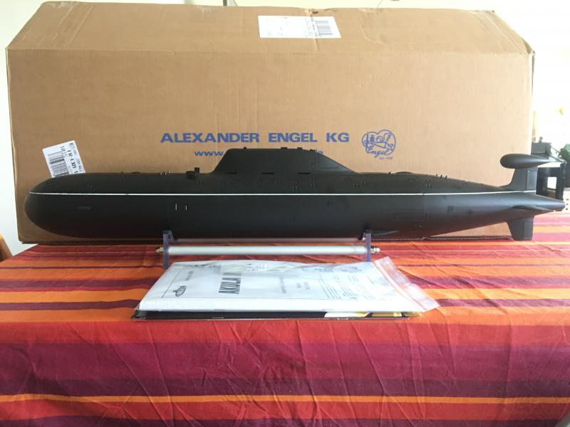
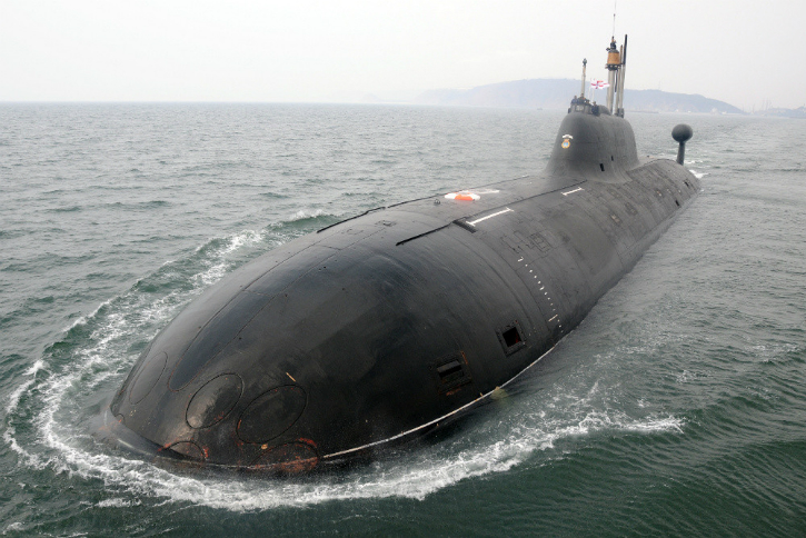
    Here is a building report of the newest Engel RC sub kit, the little Akula II in 125th scale.
    Like the 212A, the hull is made in injected/molded ABS thick plastic. It comes preprinted with control surfaces preinstalled, a real piece of cake !
    Sold in two different version, basic and SET, I ordered the second one that includes almost everything to finish it less the Tx and Rx. Ordered last Wednesday, it arrived this Monday.

    Here is the hull out of the shipping box (that I'll use as a transport crate like I did with my 212A) :


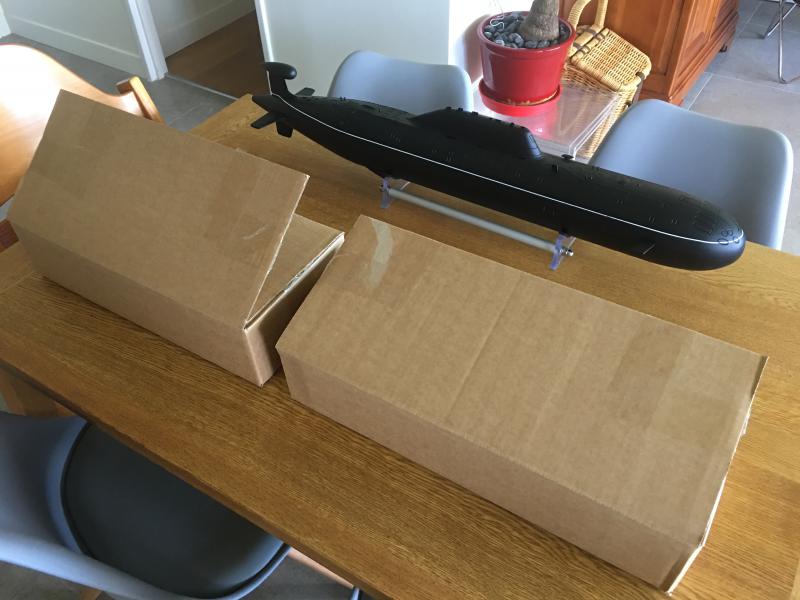
    Inside the parcel, there are two boxes with the rest of the kit. I strongly recommend to buy the stand and the Hall sensor option (to convert the piston control into a proportional command). Everything was inside these boxes, even the options...


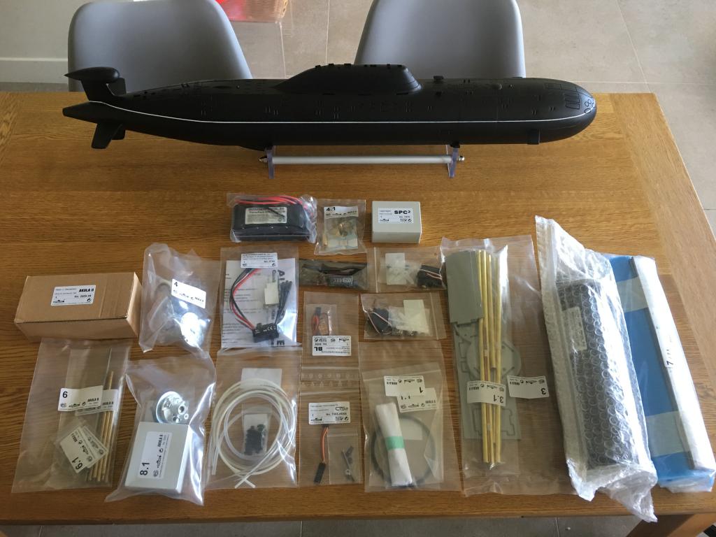
    What's inside ? From left to right :
    Wires/connectors set, Tech Rack parts, motor mount + BL motor, pressure sensor and the CS2 electronic board, NiMH batteries, ESC, tubings and bellow, 7 blades prop, UBEC, auto Reverse Drive Detection device, Hall sensor + magnets, SPC2 pitch controller, 2 mini servos, Oring + masts and periscopes, Tech Rack PVC parts, 750ml Engel piston, foam and lead ballast.

    Last edited by Antoine; 05-17-2017, 11:03 AM.
    http://forum-rc-warships.xooit.eu/index.php
  • Ralph --- SSBN 598
    Junior Member
    • Oct 2012
    • 1417

    #2
    Sure looks good sitting on the table.

    I am building this boat.
    I was told to read the instructions completely before starting.
    Dry fit everything to see where little fixes are needed.
    example: when you get to pulling the power wires through the brass tubes, it was very hard to pull the main power red and black wire through the same tube.
    I was shown that if I pulled the 2 red wires through one tube and the 2 black wires through the other tube it would be so much easier.
    It was!
    When assembling the plastic tray parts, I filed the slot corners square and everything fit much better.
    Oh, during the dry fit, make sure all the pre cut holes line up.
    It is very easy to get a frame turned 180 degree and then some later parts will not fit.

    I have less than 24 hours of build time, start to finish. . .except I had a major painting problem which I am currently correcting.
    (not the kits problem)
    ----------------------
    I was told to be careful.
    And I am doing my best.
    The very thin doors on top of the sail can me broken off easily.
    I have had to re attach the same door 3 times.
    The rear most left side. Second time, I made a wooden piece to hold the door at the right distance to make it easier to put on.

    There are photos in the instruction to show you what you are to do but the photo is a couple of steps ahead of where you are working.
    A bit confusing at times. (reason to dry fit everything)

    One other thing I learned, the decal placement instructions are not correct.
    The front 2 draft marks are too far aft placing the horizontal line forward.
    I did research to learn what these line where to know why they were were they were.
    On the side of the hull there are sonar panels.
    These lines are on and above these panels to show where not to push with tub boats.
    If you want the bow lines, you will have to make them.

    Another research find.

    The boat has different lines on the export version of the boat.
    No lines on bow or side of the hull but has 4 lines on the forward deck.

    Lines


    Different lines


    These photos may be the Akula I but the exterior look is the same as the Akula II as far as I can tell.
    The senors are different on the deck.

    I am more of a scratch builder and I enjoyed this boat build.

    Comment

    • Antoine
      Junior Member
      • Feb 2003
      • 447

      #3
      Yes Ralph, your building report inspired me to order the Akula and build my own.

      Few shots of the hull.


      http://forum-rc-warships.xooit.eu/index.php

      Comment

      • Antoine
        Junior Member
        • Feb 2003
        • 447

        #4
        Now a quick review of the kit before the building.
        When I saw the first photos of the newest Engel I immediately noticed few small glitches in the shape of the hull (nothing critical indeed). The general shape is respected and one can easily recognize the famous Russian submarine class (nothing compared to the bigger Engel Akula model that is far from being accurate).

        The Cons :
        - the sail is a little bit too tall and slightly misplaced (backwards)
        - the planes and rudders are slightly in front of the accurate position
        - the stern cone is not thin enough

        The Pros :
        - the bow is very nicely done
        - the general shape of the hull is ok
        - the scribing although it is quite deep and large is nice

        Here is a comparison of the model shape and the profil from a shipyard drawings (the bold lines show the model shape)

        http://forum-rc-warships.xooit.eu/index.php

        Comment

        • Oldus Fartus
          Member
          • Jul 2016
          • 185

          #5
          Great detail.
          I'm building the same kit.
          Let us know any helpful building tips.

          Comment

          • Antoine
            Junior Member
            • Feb 2003
            • 447

            #6
            Thanks.

            Please note a little mistake from Engel concerning the propeller. The model supplied in the kit is a right turn while it should be a left turn.


            Having noticed this before ordering the kit, I simply asked Engel to change the supplied prop.

            http://forum-rc-warships.xooit.eu/index.php

            Comment

            • Antoine
              Junior Member
              • Feb 2003
              • 447

              #7
              Day 1 of the construction (8 hours spent). The Tech Rack is almost done.


              Electric wires guides and tubing extension are made of brass tubings slided thru the PVC parts. Nothing tricky.


              Construction of the battery compartment. It is glued with medium CA and bonded to the PVC front of the piston.


              The pressure sensor is installed at the very front of the rack.


              The CS2 is simply pushed on the microswitches connectors, the rest of the wires (motor leads) is soldered.


              Quite a tricky step here. To get a proportional command of the piston, it is needed to install the Hall sensor option, this way the electronic will count the revolutions made by the main gear. For this, 4 powerful tiny magnets must be bonded to this gear, two with their North Poles facing outward and the two others facing inward. It is very important to clean the gear from any trace of grease (acetone is recommended). The rest is luck...;-)
              It requires a lot of patience but it is doable (it is my second as my 212 is fitted with this option too).


              The main gear back in place and the Hall sensor (the little black thing) installed. It is important to respect a maximal distance between the sensor and the magnets (2mm max, more and the sensor couldn't feel the magnetic field)


              The central compartment. Bonding of the nut that will hold in place the pitch controller. I used CA, activator and grease inside the nut to avoid the bonding of the screw to the nut.


              Screwing of the bars that will hold the central compartment.


              Construction of the central compartment, be careful of the way you glue the PVC parts, check the holes alignment. Installation of the servos.


              Making of the battery pack. Two 6V 3500mAh in serial. It requires basic soldering skills.


              Making and installation of the wires extensions. These wires should pass inside the brass tubing we saw at the beginning of the construction. It sounds easy but it can turn into a long and difficult moment. The main battery extension wires are made from quick thick wires. They should be pushed inside the largest brass tube. A piece of cake ? No as the room is tight.
              Ralph has a very simple and clever solution for this : use one brass tube for the red wires (one thick and one thin) and the other tube for the black ones.
              As I wanted to build this model as close as possible from Engel's instructions, I followed the manual.
              My advice : follow Ralph's solution.
              Anyway, I managed to slide the wires in the tube at great and useless effort.


              Making of the main power socket and plug and charging plug. Clever solution, I like the MPX plugs. But be careful when soldering it. Use a multimeter to check for any short !


              The socket installed in the central compartment. The external BEC system (UBEC) is beneath the socket, connected and soldered to it.


              The ESC


              The central tray screwed to the piston.


              The battery in its compartment.


              Will it fit ?? :-)

              http://forum-rc-warships.xooit.eu/index.php

              Comment

              • Ralph --- SSBN 598
                Junior Member
                • Oct 2012
                • 1417

                #8
                This all looks so familiar. (like it was just yesterday, I was taking it all a part and putting it back together again. Several times)

                The wire trick was told to me by Will Oudmayer, who had just finished two of these boats.

                A suggestion, before sliding the tray in to the hull, use the Velcor strap to hold the batteries in their place.
                I did not modify my tray and it slid right in with a little jiggling.
                How ever while checking things, I happened to roll the hull over past 90 degrees and one of the batteries slid up out of the tray a little which caused the tray to become stuck until I shook the battery back in to it's place.

                Like closing a drawer that something is sticking up and you push it down to close the draw but they it pops up again and you can not open the draw.

                (Another item to watch out for by Will. "Be careful of the little doors on top of the sail. They tend to come off rather easily." Medium CA puts them right back on. I do know. . more than once and it's the same one.)

                Comment

                • Antoine
                  Junior Member
                  • Feb 2003
                  • 447

                  #9
                  Yes Ralph, I wondered what was this Velcro strap in the connectors and wires set when I saw the photo in the instructions manuals...

                  Day 2 (3.5 hours).

                  Here is how the hull opens. It will be watertight with the help of the Oring on the bajonet.


                  The rear bulkhead is already installed and sealed with all the tubing and holes for the ballast, pressure sensor and pushrods. The rudder and planes yokes are already installed too. When I wrote this kit was perfect for a lazy boy like me...

                  Installation of the rubber bellows that seal the pushrods. They are hold in place with the help of a small Oring.


                  The collars that hold in place the pushrods inside the clevis tube.


                  Before mounting the motor, it is important to put the pvc and silicon tubes.


                  The motor is screwed to its mount, the watertightness is made by an Oring. The motor shaft and the prop shaft are joined by a coupler (do not forget to make a flat spot on each shaft). The prop shaft pass thru a shaft seal (Simmering).
                  In the Engel website it is written that the seal should be installed with the spring facing the prop. In the Akula instructions, the opposite is written so I contacted Engel to get the correct info. Gregor replied me it was irrelevant...so I chose to put the spring inwards (to protect it from the water).
                  I do not remember having had such a dilemma when I built the Lafayette and the 212, getting old is not a good thing.


                  The mount is installed on the rear bulkhead with four nuts. Use the right tool to screw the nuts, it can be tricky.

                  http://forum-rc-warships.xooit.eu/index.php

                  Comment

                  • Antoine
                    Junior Member
                    • Feb 2003
                    • 447

                    #10
                    Day 3.

                    Wiring and attaching the rack to the stern cone.

                    The 4 channels used : rudder, dive planes, motor and ballast piston.


                    The servo arms.


                    Wiring of the BL motor for the upcoming tests.


                    All is in working order !

                    The rack is attached to the stern with the help of 4 threaded bars, 4 threaded rods and 4 screws + nuts.


                    Needs some cleaning.


                    Wires rearrangement done !


                    Final tests of the electronics :

                    Last edited by Antoine; 05-31-2017, 11:13 AM.
                    http://forum-rc-warships.xooit.eu/index.php

                    Comment

                    • Ralph --- SSBN 598
                      Junior Member
                      • Oct 2012
                      • 1417

                      #11
                      You are coming right along.
                      Looks good.
                      --------------
                      Ihave another item that may be of interest.

                      During trimming, I found that the piston moves enough water to pop the bottom tail cone hatch off.
                      I cleaned the paint from the two magnets hoping that would provide better connection.
                      The piston still cause the hatch to pop off.

                      For now I will use a piece of clear tape to hold it on but I will come up with something to mechanically hold the hatch on.
                      I am going to look for a small screw, like the 4 that hold the lid on the power section.
                      Or I will build some sort of latch that I can turn with a screw drive through one of the holes in the hatch.
                      Or maybe a simple string attached to the hull and the hatch so, it can not be lost.

                      I like the idea of the small screw, in the seam just in front of the magnet.
                      Counter sunk flush with hull. (painted black)

                      Comment

                      • Ralph --- SSBN 598
                        Junior Member
                        • Oct 2012
                        • 1417

                        #12
                        Looking at your photos, I thought I had missed something.
                        You have a green wire that I do not have.
                        Then I realized, that is your Rx antenna.
                        Relieved! ;^)

                        Comment

                        • Antoine
                          Junior Member
                          • Feb 2003
                          • 447

                          #13
                          Thanks for the advice Ralph.

                          Day 4.


                          Electronics tested, assembling validated.
                          It is time to keep on the building and install the lead weights. I tried something, I placed the weights to counter just a little bit the torque of the prop. Will see if it is ok during the final trimming.


                          Masts and periscopes made in a flimsy resin are included in the kit. I think it is a quite good idea from Engel, as these parts will act as fuse if the model hit something near the sail. But, as an optimistic and careful driver, I decided to build stronger masts (and a little bit more accurate).
                          Like Ralph did, I only used the top of the aerials and bonded them to brass tubes in scale diameters.
                          I did turn in a homemade lathe an observation periscope and discard the two of the kit. I made them removable from the sail to ease the transport.


                          Here they are on the sail.


                          End of day 4. It is almost done ! Not much remains to be done, the painting and the depth markings.

                          http://forum-rc-warships.xooit.eu/index.php

                          Comment

                          • Oldus Fartus
                            Member
                            • Jul 2016
                            • 185

                            #14
                            How did you fasten the weights? Tape? What brand?

                            Will you epoxy in place eventually?

                            Comment

                            • Antoine
                              Junior Member
                              • Feb 2003
                              • 447

                              #15
                              I put 3M double sided tape (very thin) to secure them for the balancing but will epoxy them to protect the rack and limit the lead corrosion.
                              http://forum-rc-warships.xooit.eu/index.php

                              Comment

                              Working...