It is not usually recommended to use 100% fill. The reason being is that you have a wide temperature differential across the part as it is being printed. The part can warp, and in extreme circumstances can even crack. I usually go with a 3.2mm exterior wall thickness, although I have gone as thick as .20" and allow a lighter latticed infill. The plastic reacts differently than if it was injection molded, where the part temperature is homogenous across the profile off the geometry. This parts will automatically be 100% filled just due to the geometry and print parameters of the machine/software. Thin parts tend to be a bit more forgiving, but they can still warp.
-
Regards,
Matt -
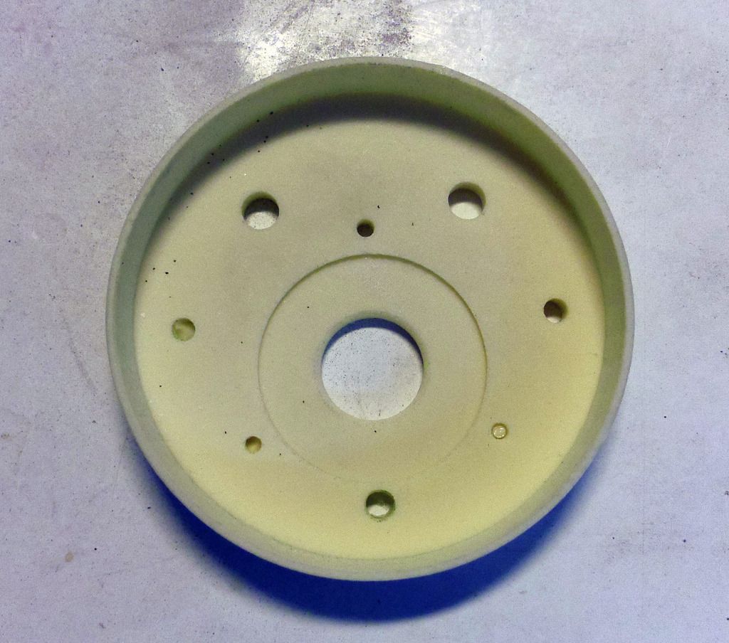
These parts are solid.Comment
-
Those parts look like they're laser sintered. The material used is usually a type of nylon, very strong, but probably absorbent.Comment
-
early on he had problems with the heat being uneven but he has modified his printer and it now maintains a more consistant temp with a clear enclosed shield surrounding the print bed and I do get less warp in the parts now but id like to use a few of the smaller parts as they are and not have to mold every single piece he prints...but the ones that I could use have all this infill which worries me that if it cracked it would then take on water and change the buoyancy... There has to be a happy medium cause what I get it is huge spaces in the material and I see other peoples parts that are just so much better... he has gotten better but I just feel hes still learning ..... and no we made a trade so its not costing me for the most part but I do contribute some now and then when it comes to material costs....Last edited by wingtip; 03-25-2016, 10:59 AM.Comment
-
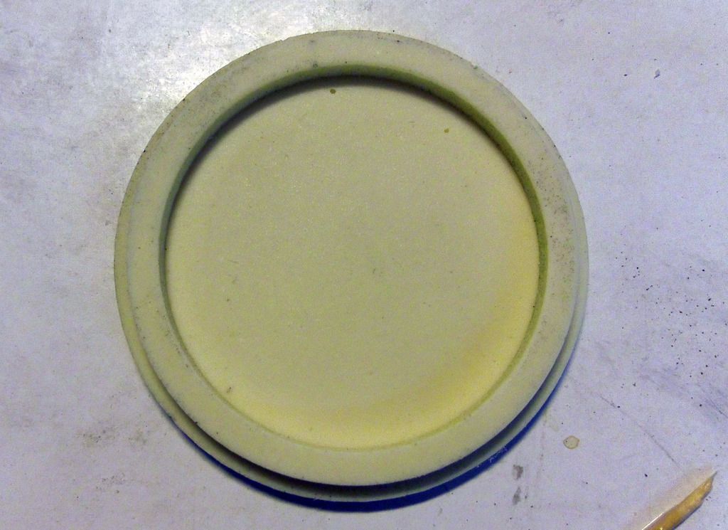
They are just masters for silicon moulds. The actual parts will be cast in PU.Comment
-
Understood, Andreas, I saw that in your earlier post.
I think it's worth addressing that the kind of machines that Shapeways offer access to will be a lot better than what an individual is likely to have in a home workshop.Comment
-
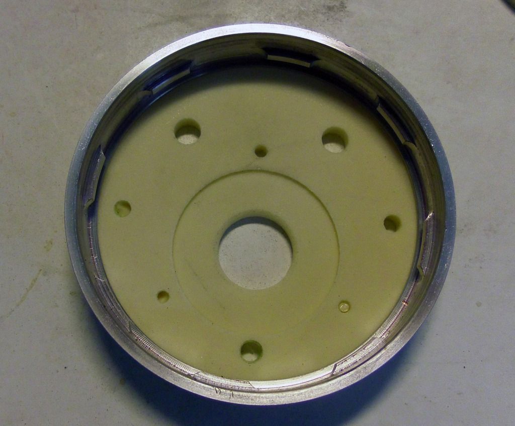
Shapeways offers a plethora of different materials and resolutions. Highly detailed, smooth surface stuff for smaller parts or tuff like these structure parts.Comment
-
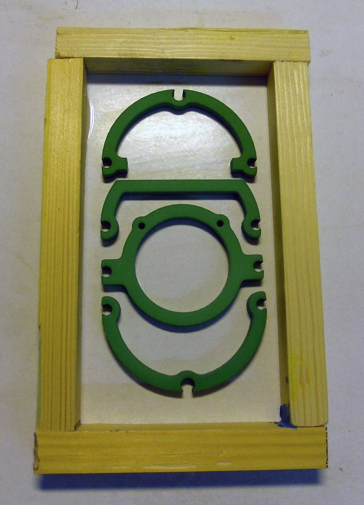
And here we go: To make reproduction easy I want to cast the structure parts using PU resin. Therfore I have to make silicon moulds from the masters. Glue the masters to a flat board, frame.....
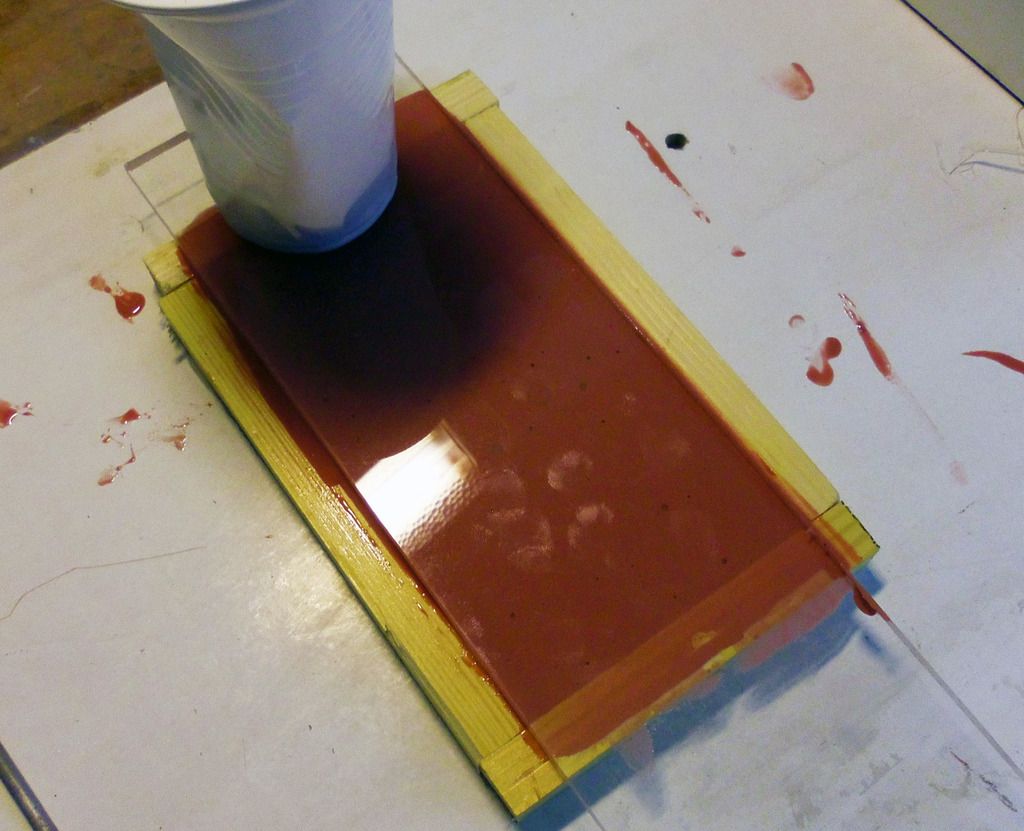
Cover everything in 2K silicon.....
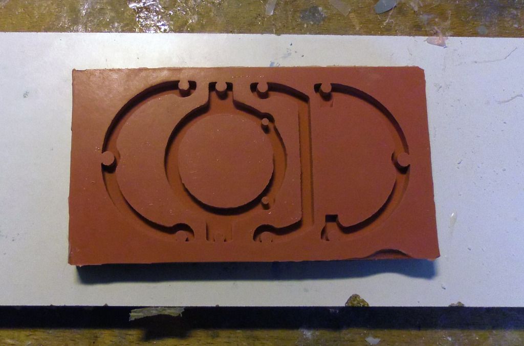
and we have a mould.
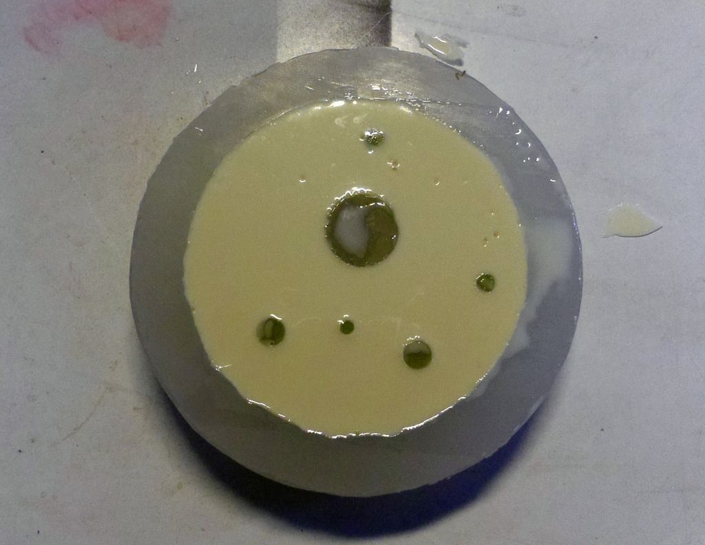
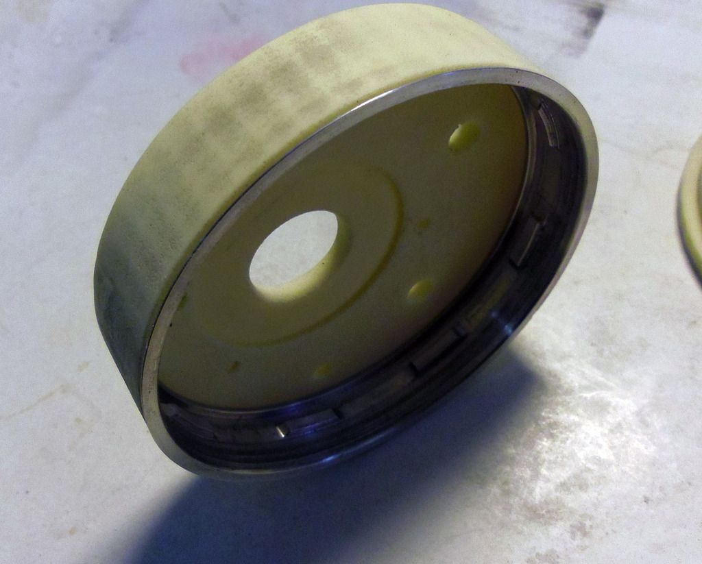
And the first cast parts.

Couldn't be easier.
Moulds for the front and back bulkheads are next.Comment
-
As promised, the silicon moulds for the front and aft bulkhead are done, and the first parts are cast:
The bajonet catch fits tightly:
The counterpart is already glued into the WTC tube:
And complete:
Next is the inner structure...Comment
-
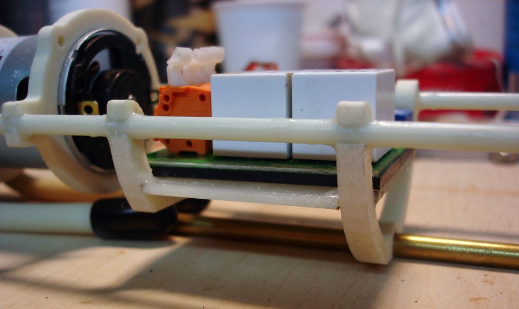
Well, a quick snap together of the inner structure:
The end plate of the peristaltic pump has been trimmed to fit the PU cast supports:
Everything is held together by two 4mm diameter GRP rods and a 5 mm diameter brass tube, which also serves as water intake for the pump:
Well, basic inner structure done in about 1 hour - had worse deals than that:

Comment
-
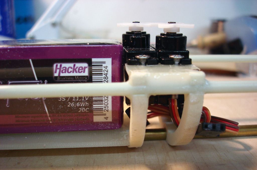
During the week I glued together the part of the inner strcuture. The pump is screwed to the support frames. Behind it sits the pump controller on a 2 mm thick GRP board. The free space will hold the rubber sack for the water. Then the LiPos and behind them the two servos for the aft planes.
Comment
-
I see you are at it again.
You building such simple system that make the rest of us look like we are wasting our time trying to design equipment trays.
Keep it up.Comment
-
I like "simple".....;-)Comment
-
But honestly, this is the 4th or 5th version of this WTC design. The first ones were much more complicated and had much more parts. It's just by going through some simplification loops that designs become simple. And using CAD makes a trial and error approach possible without the need to build the real thing.Comment
-
Simple is the answer....
------------------
I have a specialized Gizmo I have been working on off and on for about 6 years.
It has gone through 5 or 6 generational changes.
It has gone from a 144 boat to the now 1/72 boat.
Easier to work on bigger parts.
Each time I made changes, I removed things and simplified it.
Last week I finally got it to work reliably enough to use it in the boat.
I like it but it is one of those, "I have done it. No need to do it again things."Comment

Comment