Fun With Magnets

Collapse
X
 
  • Time
  • Show
Clear All
new posts
  • Oldus Fartus
    Member
    • Jul 2016
    • 185

    #1

    Fun With Magnets

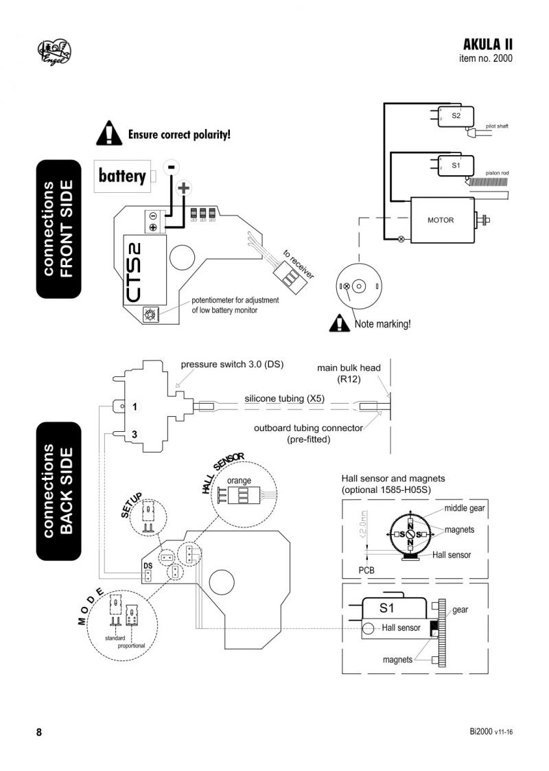
    So I have started an Engel/Akula II kit and hit my first “interesting” problem. I opted for the Hall Sensor upgrade so the ballast tank fill can be proportional. The kit involves installing 4 small 4mm cube Neodymium magnets by “super gluing” the magnets at four places symmetrically around the perimeter of the ballast tank’s drive gear.
    The magnets are arranged 2 mm from the edge of the gear 90 degrees apart in an alternating N-S-N-S orientation around the perimeter.
    Simple, right? Wrong!
    Placing a drop of CA at the first magnet location and carefully placing the small cube magnet in the CA, I watched as the magnet slooowly rotated its position in the drying glue to magnetic North…hmmm, that’s not going to work (time to bust out the bottle of CA Undo!).
    After removing the magnet, I oriented the gear and magnet to magnetic North and re-glued the magnet 2 mm from the edge of the gear without it rotating again…success!
    Next I rotated the gear 180 degrees and repeated the process for the opposing magnet, which was also oriented with the North side of the magnet toward the gear teeth. Placed the cube magnet in the CA, let go and POOF it was gone, right before my eyes! Where did it go? It shot directly across the gear, attracted to the first magnet and its momentum carried it across the gear and directly under the first magnet…hmmm, that’s not going to work either!
    Next tried holding it with wooden clothes pins, hobby clamps & etc. but it is just too small and too strong.
    Finally made a fixture from a piece of the scrap PVC of the bulkheads that came with the kit; however, if you do this, the u-shaped opening must be a snug fit or the opposing magnet will cause the magnet to rotate within the fixture due to the N-S attraction of the opposing magnet already on the gear!
    Click image for larger version

Name:	DSC_4067.jpg
Views:	1
Size:	58.0 KB
ID:	136955
  • Ralph --- SSBN 598
    Junior Member
    • Oct 2012
    • 1417

    #2
    I just went through this this morning.
    First try was with needle nose pliers.
    Could not let go of the magnet.

    Next, I just held the magnet with my fingers until the CA hardened.
    Checking magnet polarity, I then put the 180 degree magnet on.
    Held it until CA cured.
    Did the same with the last two.

    I thought about making a fixture to hold the magnets but got it done without.

    I am stopped because I don't under stand where the jumper plugs go on the circuit board. (Setup and Bail)
    No drawing showing this. It would help a lot.

    Brought the instruction booklet in from the shop and plan to re read it all later today.

    My Akula II only needs the plugs sorted out and I plan to clear coat the hull.
    ---------------------
    The 4 square magnet blocks are small.
    I placed a big steel bar next to where I was working. 3"x3"x 15" I use it to hold things down.

    Had I drop any of these magnets (dropped 1), I would find it on the steel bar.
    .

    Comment

    • Oldus Fartus
      Member
      • Jul 2016
      • 185

      #3
      Originally posted by Ralph --- SSBN 598 View Post
      I just went through this this morning.
      First try was with needle nose pliers.
      Could not let go of the magnet.

      Next, I just held the magnet with my fingers until the CA hardened.
      Checking magnet polarity, I then put the 180 degree magnet on.
      Held it until CA cured.
      Did the same with the last two.

      I thought about making a fixture to hold the magnets but got it done without.

      I am stopped because I don't under stand where the jumper plugs go on the circuit board. (Setup and Bail)
      No drawing showing this. It would help a lot.

      Brought the instruction booklet in from the shop and plan to re read it all later today.

      My Akula II only needs the plugs sorted out and I plan to clear coat the hull.
      ---------------------
      The 4 square magnet blocks are small.
      I placed a big steel bar next to where I was working. 3"x3"x 15" I use it to hold things down.

      Had I drop any of these magnets (dropped 1), I would find it on the steel bar.
      .
      Ralph - Glad to hear there is another Akula II builder on the Forum!
      I too wondered about those plugs. If you read later in the setup section of the assembly instructions there is a procedure as to how the jumpers work but nothing I saw about which goes where & etc.
      If you figure it out let me know.
      BTW, how were you going to "de-grease" the hull safely and what Clear Coat are you planning to use?
      Thanks,
      Pete

      Comment

      • Ralph --- SSBN 598
        Junior Member
        • Oct 2012
        • 1417

        #4
        I run my boats at Yorba Linda Park.
        One of the others there, Will, has built 2 of these boats.
        1 for Mike Dory and 1 for his own.
        In fact I have on my kitchen table a Hall Sensor for him that I ordered with my stuff from Engels.

        I am going to e-mail him and ask for help.
        He has a few things he did different from the instructions that made building so much easier.
        Hope he can explain the Hall Sensor.
        He use them in his scratch built ballast cylinders.

        Example: I pulled the two power wires through the brass tube and had to use a string to get it through.
        Talked to Will the following Saturday and he showed how he pulled both red wires through one brass tube ad 2 black wires through another brass tube.
        One wire is larger than the other but having 1 of each size made it so much easier.
        I in fact removed my original wires and did it the way Will had.
        They just pushed right through with out needing a wire or string to help.
        He also pointed out where the two small ballast weights where placed in the 2 boats he put together.

        It was the running of his boat that made me make up my mind about getting this kit.

        If you are interested, I have a Building Log web page.
        Akula II build

        and lots more. . . . Submarine stuff
        Last edited by Ralph --- SSBN 598; 05-06-2017, 05:36 PM.

        Comment

        • Ralph --- SSBN 598
          Junior Member
          • Oct 2012
          • 1417

          #5
          De-greasing?
          I will use soap and water on the outside.
          I will paint with what Will suggested and used to painted his boats.
          Rust-oleum painter's touch 2X Ultracover Matte Clear

          I did the inside of the boat with a wooden stick that I attached a rag on and used Paint Thinner to wipe down where the ballast weight tape was doing to go.

          Comment

          • Oldus Fartus
            Member
            • Jul 2016
            • 185

            #6
            Ralph - Thanks for the links and all the tips...keep em coming as I know I will have more "interesting" problems to solve as I go along.
            Pete

            Comment

            • Oldus Fartus
              Member
              • Jul 2016
              • 185

              #7
              Originally posted by Ralph --- SSBN 598 View Post
              De-greasing?
              I will use soap and water on the outside.
              I will paint with what Will suggested and used to painted his boats.
              Rust-oleum painter's touch 2X Ultracover Matte Clear

              I did the inside of the boat with a wooden stick that I attached a rag on and used Paint Thinner to wipe down where the ballast weight tape was doing to go.
              Do you plan to eventually remove the ballast weight tape and permanently epoxy the weights in place as the Engels Manual suggests?

              Comment

              • Ralph --- SSBN 598
                Junior Member
                • Oct 2012
                • 1417

                #8
                I will probably leave the tape.
                I am allergic to epoxy.
                Just the fumes will effect me.

                The ballast weights are not in the wet so I do not see an issue as long as I check it every so often.
                I may make a plastic piece to go over the top to make the long tray slide easier.
                Not to that point yet.
                What ever I do, will go on the building log and on the other forum.

                Currently removing a bee hive from under my front porch.
                Allergic to bees or any insect sting as it is.
                Neighbor is bee keeper and he is doing his thing now.
                Hoping the rain holds off.
                It tried t rain about 10 minutes ago, but quit.

                Comment

                • Ralph --- SSBN 598
                  Junior Member
                  • Oct 2012
                  • 1417

                  #9
                  I have been reading the instruction booklet.
                  Came across one of those "how dumb was I?" moments.

                  The information I wanted was right here in front of me.
                  I just didn't look at it.

                  I read the instructions but failed to look at the drawing associated with the instructions.
                  Hall Sensor installation on page 9.
                  However I really didn't look at page 8 with drawing of the the connections of the pressure sensor and the Hall sensor.
                  Lower left corner is a drawing of the circuit board and where all the plugs and jumpers go.
                  The Mode for proportional (using Hall Sensor) looks to be with the jumper in place.
                  Shows how the three wire plug is to be oriented.

                  The pressure sensor plug doesn't matter which way the red and black wires are positioned as this is just a through circuit.

                  Yep ! Everything was there, I just was seeing it.

                  Tomorrow, I need to check my magnets.
                  I think I have one installed incorrectly.

                  Comment

                  • Antoine
                    Junior Member
                    • Feb 2003
                    • 447

                    #10
                    Having recently built a 212 with the Hall sensor option, I came across myself on one of those moments...

                    But I must say tha the informations relative to the installation and setup of this option could have been better organized in the instructions.
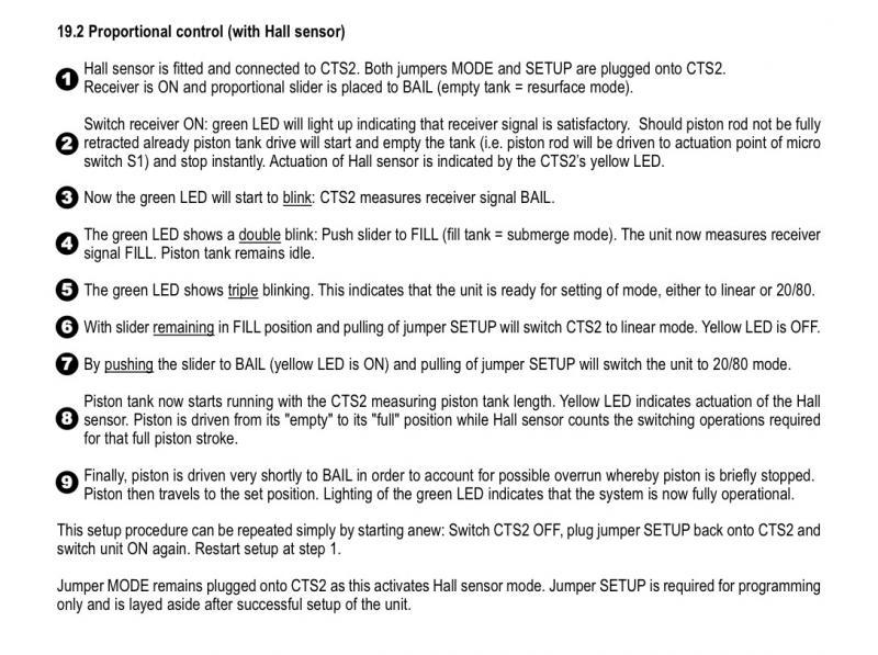
                    Anyway, here are the drawing and instructions for this option. The mode jumper must remains in place and you have two ways to set up the option, fully proportional or 80/20.


                    A short video of the piston working proportionally.

                    Last edited by Antoine; 05-07-2017, 11:11 AM.
                    http://forum-rc-warships.xooit.eu/index.php

                    Comment

                    • Ralph --- SSBN 598
                      Junior Member
                      • Oct 2012
                      • 1417

                      #11
                      Yes, that is the drawing. Page 8.
                      The information was not where I was looking for it.

                      But it is there.

                      Thanks for posting the pages drawings.

                      Comment

                      • Antoine
                        Junior Member
                        • Feb 2003
                        • 447

                        #12
                        Ralph, I do not thank you...
                        Because of you I just ordered this little Akula.
                        I'll write a french building report soon.
                        http://forum-rc-warships.xooit.eu/index.php

                        Comment

                        • Ralph --- SSBN 598
                          Junior Member
                          • Oct 2012
                          • 1417

                          #13
                          BE careful when handling the hull.
                          There are several small plastic parts on the outside of the hull that can be broken off.

                          So far, I have had to re attach 1 mast door and the tall piece on the deck in front of the sail.

                          Best advise I received was to dry fit everything before making it permanent.
                          There are a couple of parts that will go together that can be reversed.
                          Make sure to look down through the frame holes to make sure they are all aligned.
                          If not, some parts will not slide through as they are suppose to and disassembling glued parts can be a lot of work.
                          The Akula II kit is not a kit you build, it is a kit you assemble.

                          I have built submarines and sailboats from scratch, from hull kits and now this assembly kit.
                          THis boat was a pleasure to work on.

                          Comment

                          • Antoine
                            Junior Member
                            • Feb 2003
                            • 447

                            #14
                            Thanks for the advices, Ralph.
                            I built the 212 that is very close in terms of design and it was indeed a real pleasure (no hassle, 3 days and nights and it was done, balancing in the tub included). I totally agree when you write it is a kit one assemble.
                            http://forum-rc-warships.xooit.eu/index.php

                            Comment

                            • Oldus Fartus
                              Member
                              • Jul 2016
                              • 185

                              #15
                              Ralph, Are you using UBEC #3775?
                              If so, where did you pick up the power?
                              Also, are you using Reverse Drive Detection?
                              The wiring diagram shows a power connection for #8454 (no BEC Version)
                              Since there is no power wire on the #8455 (BEC Version) do you think it is powered from the ESC?

                              Comment

                              Working...
                              X