Time for an update!
Cradle supports for a 50mm cylinder. Designed and CNCed, way to many of them
A bit later four of these have been glued in position. They come in two sizes as the Astute's hull is wider at the bow.
Now that part of this building long is a little unnecessary as you can simply buy stainless steel or brass inserts, but because I had none at the time, I decided to make my own. I've used a 6mm threaded rod, which I have drilled with a 2.5mm drill at first and tapped a M3 thread inside right after.
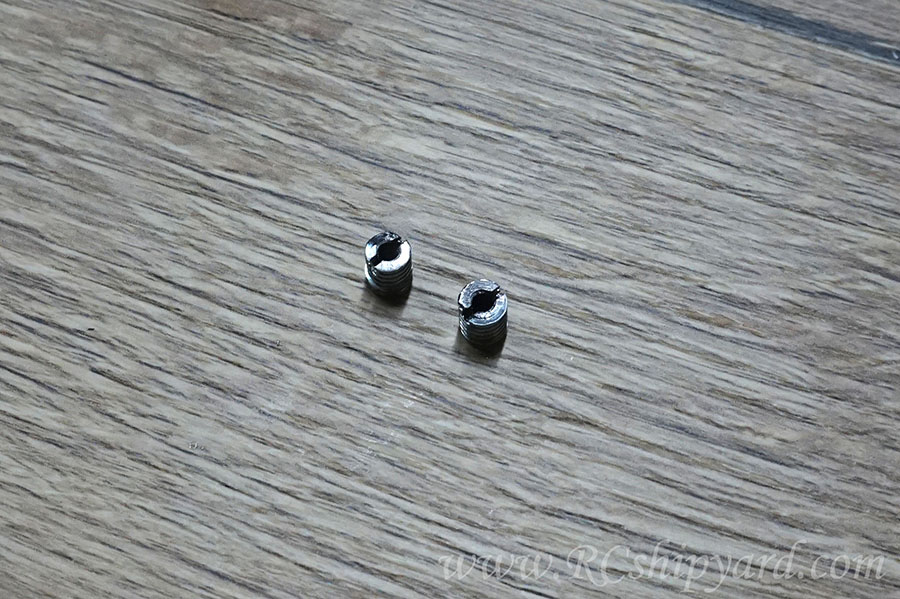
Then there was a need of cutting in a slot for the screw driver
and quickly 3 stainless inserts were born (one of those was already in a model). They all will go into the remaining pylons in the upper part of the hull as a part of the hull locking mechanism.
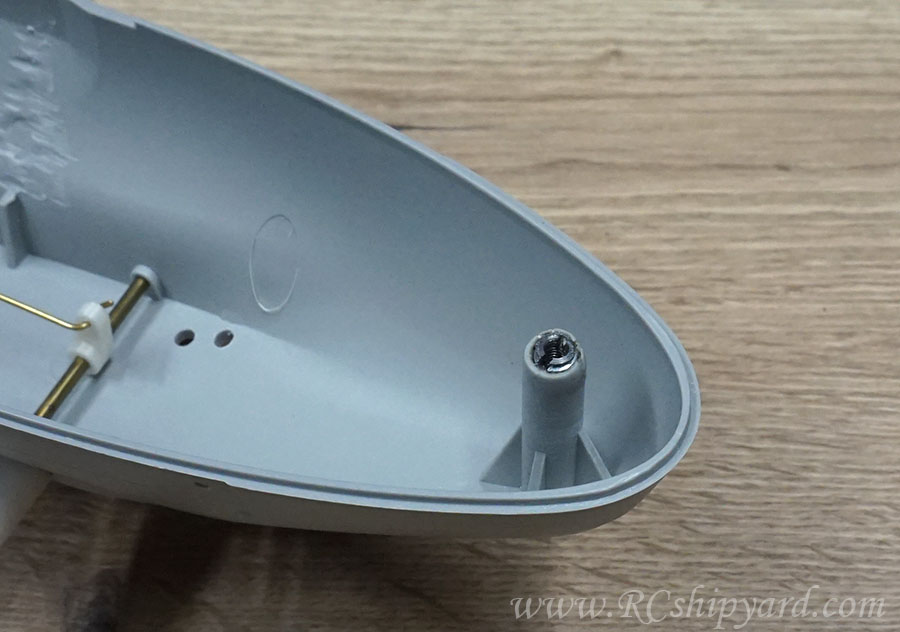
And the insert in it's place:
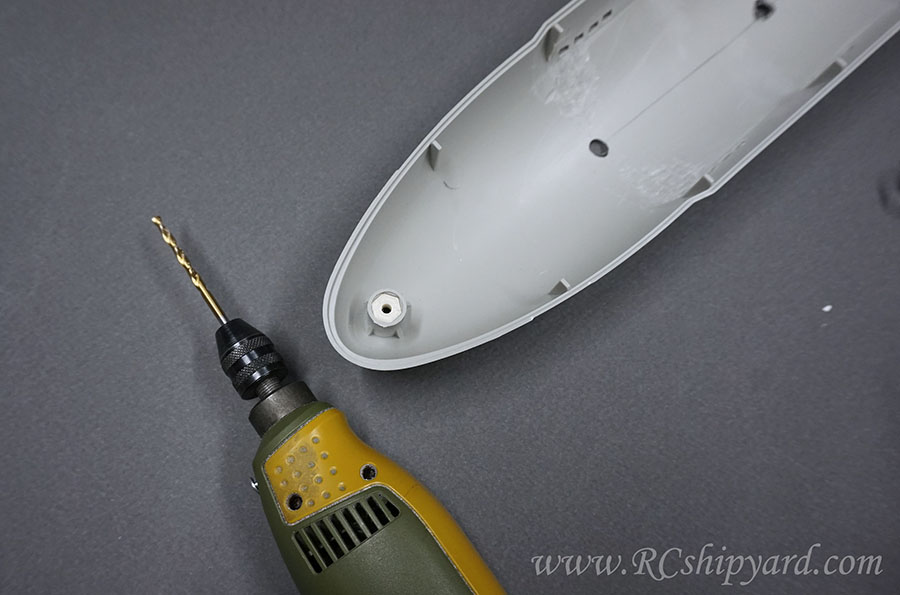
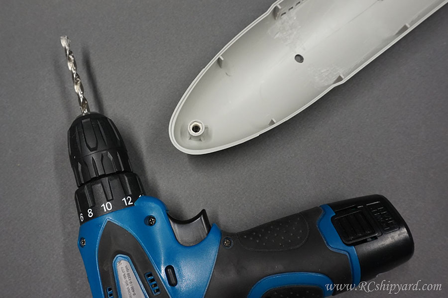
So the lower part of the hull requires drilling 3 holes for the three M3 screws (my M3 screws have a 6mm hex head). It's very important to make the holes parallel to the pylons with the threaded inserts in the upper hull, so I decided to drill them in 3 steps. Each step with it's own drill template. Template one - 2mm
Template number two - 4mm
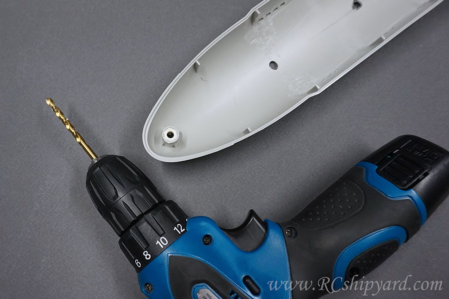
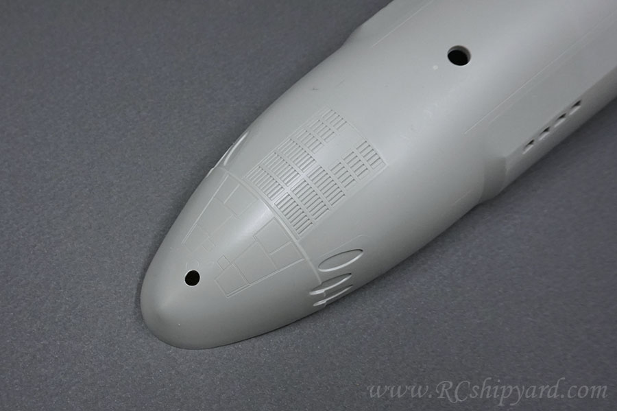
Template number three - 6mm
My other reason for dividing the drilling process into 3 steps was, that I really wanted a nice, clear edge of the screw holes in the lower hull.
And that's it for today's work!
Cradle supports for a 50mm cylinder. Designed and CNCed, way to many of them
A bit later four of these have been glued in position. They come in two sizes as the Astute's hull is wider at the bow.
Now that part of this building long is a little unnecessary as you can simply buy stainless steel or brass inserts, but because I had none at the time, I decided to make my own. I've used a 6mm threaded rod, which I have drilled with a 2.5mm drill at first and tapped a M3 thread inside right after.
Then there was a need of cutting in a slot for the screw driver
and quickly 3 stainless inserts were born (one of those was already in a model). They all will go into the remaining pylons in the upper part of the hull as a part of the hull locking mechanism.
And the insert in it's place:
So the lower part of the hull requires drilling 3 holes for the three M3 screws (my M3 screws have a 6mm hex head). It's very important to make the holes parallel to the pylons with the threaded inserts in the upper hull, so I decided to drill them in 3 steps. Each step with it's own drill template. Template one - 2mm
Template number two - 4mm
Template number three - 6mm
My other reason for dividing the drilling process into 3 steps was, that I really wanted a nice, clear edge of the screw holes in the lower hull.
And that's it for today's work!
Comment