Trumpeter 1:144 Astute conversion

Collapse
X
 
  • Filter
  • Time
  • Show
Clear All
new posts
  • Jakub
    Member
    • May 2021
    • 34

    Trumpeter 1:144 Astute conversion

    Hello there!

    As some of you know, some time ago I've started a conversion for the Trumpeter's 1:144 Astute. I thought I'll make that boat and complete my 1:144 RC collection as I already had all the other 3 Trumpeter 1:144 models converted to RC (Soryu, Kilo and the Seawolf). Sadly, at some point the build was held cause of overwhelming amount of work, so now - as I'll have some spare time, I plan to finish this model. I thought It might be a nice idea to show people a wider audience how I'm dealing with that little rascal.

    So first let's get up to date what's has been already finished:

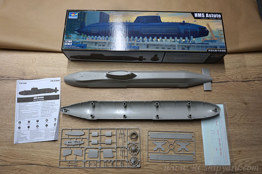
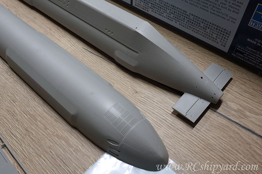
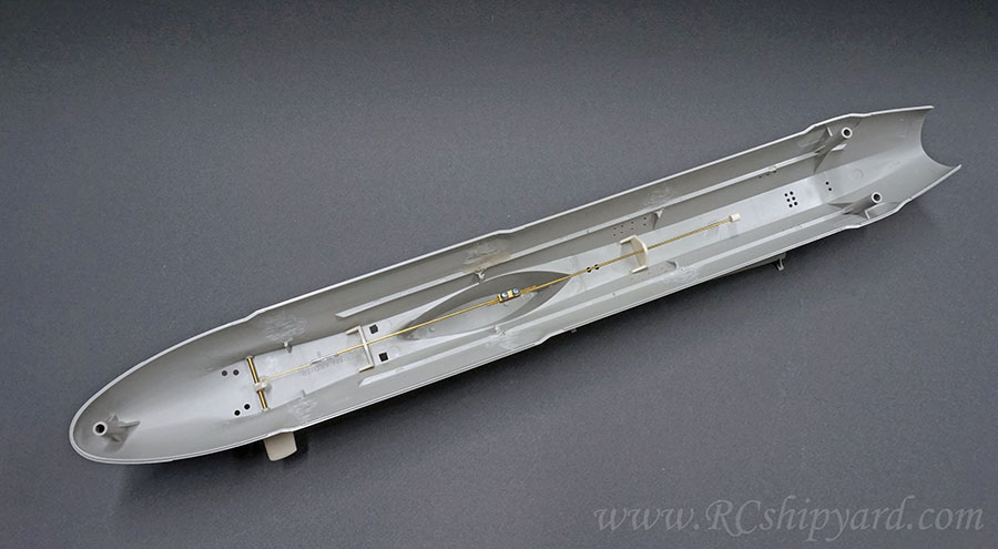
    The box content is very modest. We get the hull split into two parts (upper and lower) and two frames of elements, where one of these frames is only the boat stand. Very, very modest content even for a modern sub. The hull lacks many details and looks a lot more poorer and simpler than for example the Soryu model – which has lots of hull details – including the square plated anti sonar square coating.


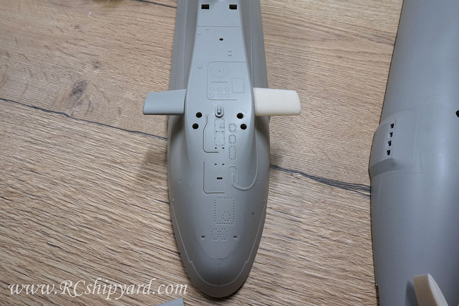
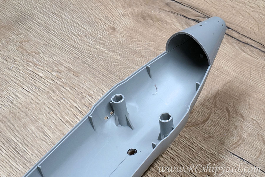
    The hull itself is quite thick - which is good, but requires some work, if we want to fit a 50mm (about 1.96inch) WTC inside. So first I had remove the 3 pairs of the middle pillars and the single one in the stern.


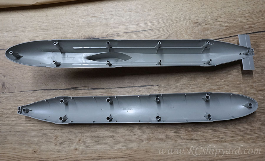
    Removing the pillars was an easy job in general. I’ve used my trusty Proxxon mini cutter with a disc bit at first, then a bit with a pink sanding stone.


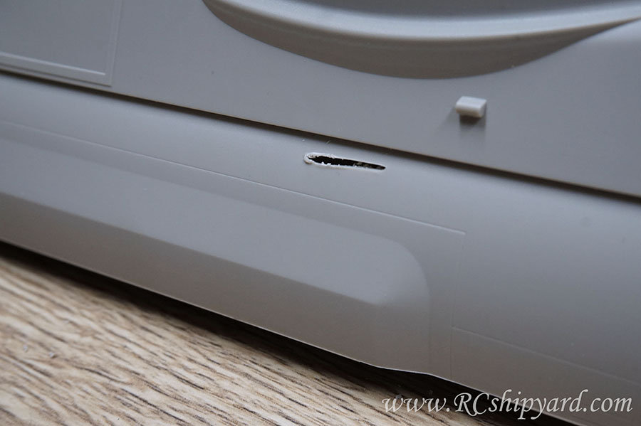
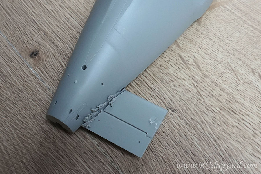
    And as in everything - if you'll feel a little to confident when you're doing something - a mistake will likely to happen – I did cut through the hull at one point. Not a big deal as it’s an easy thing to repair with Tamiya putty, but I should have been more careful when cutting out one of the pillars:


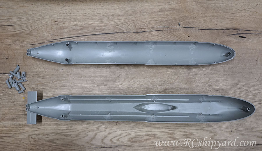
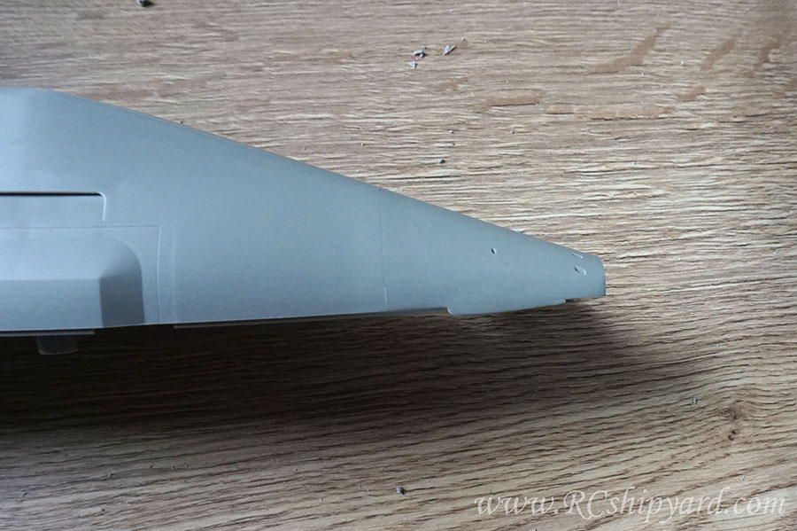
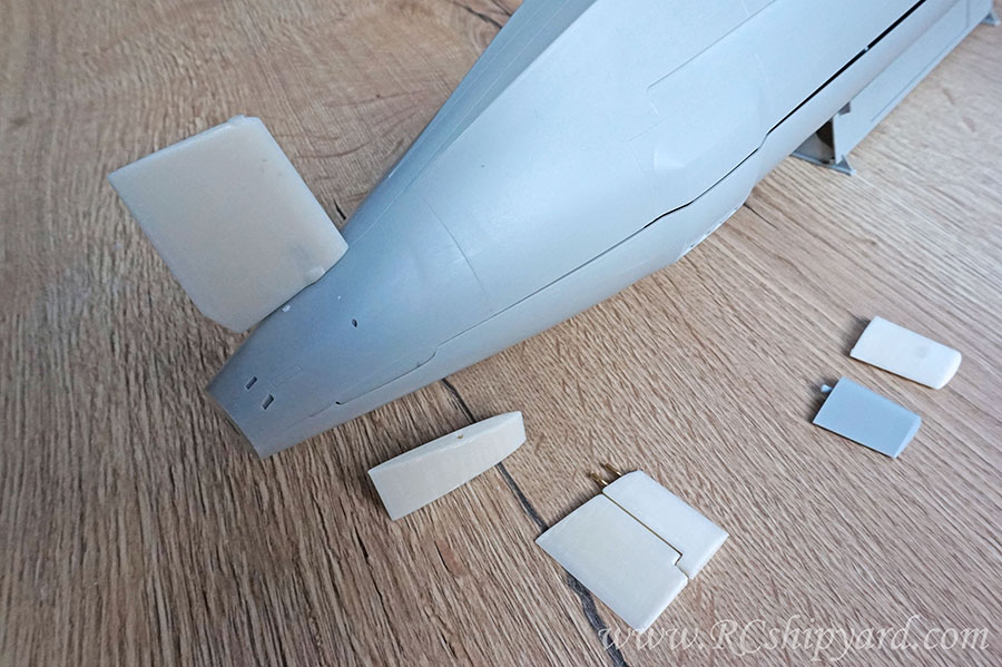
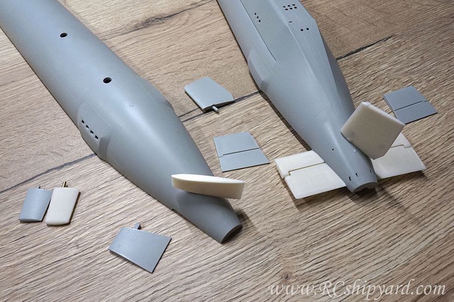
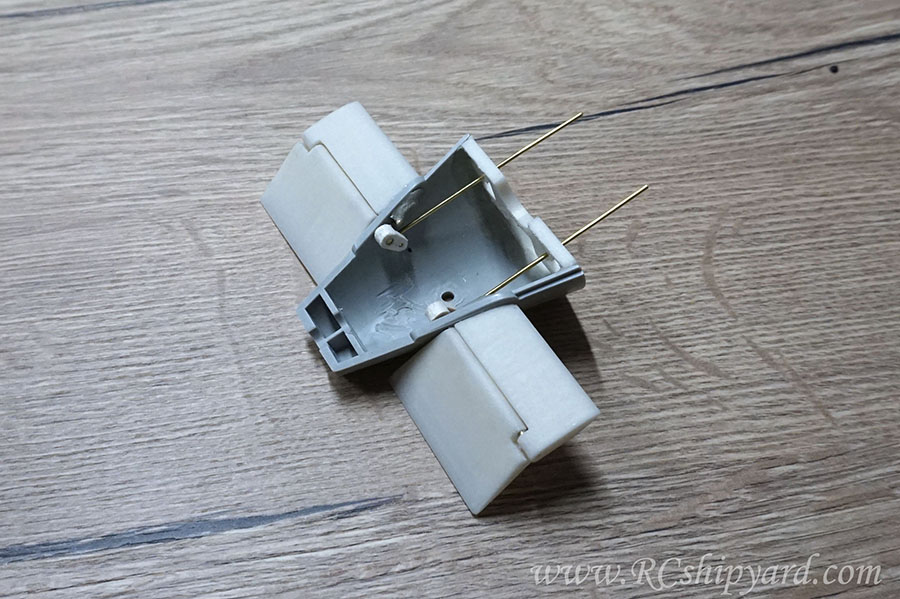
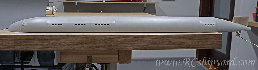
    With the pillars gone the time came for the stern diving planes, which sadly are a solid part of the hull in all the new Trumpeter 1:144 models, so they’ll have to be removed:


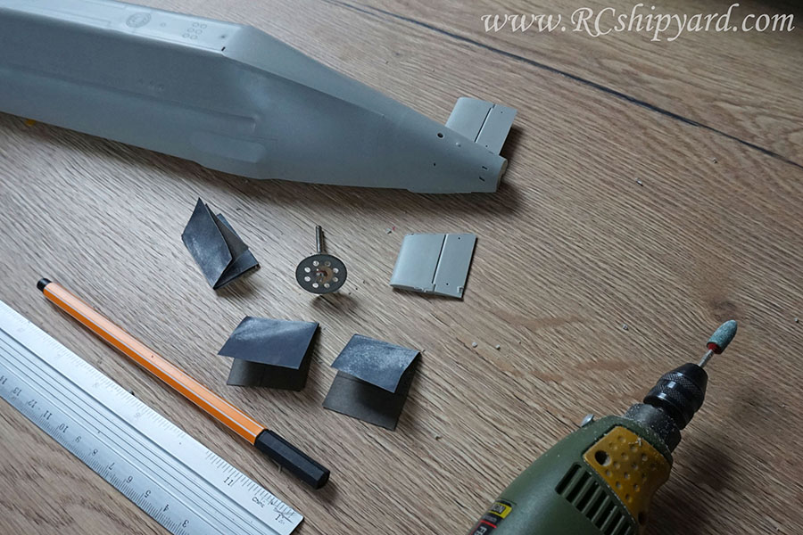
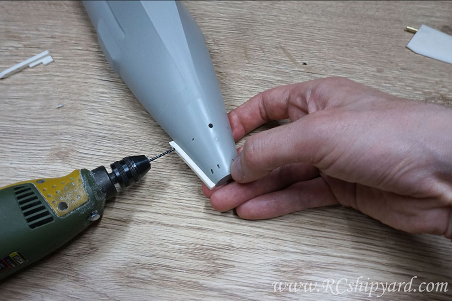
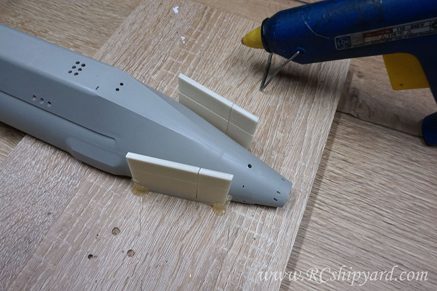
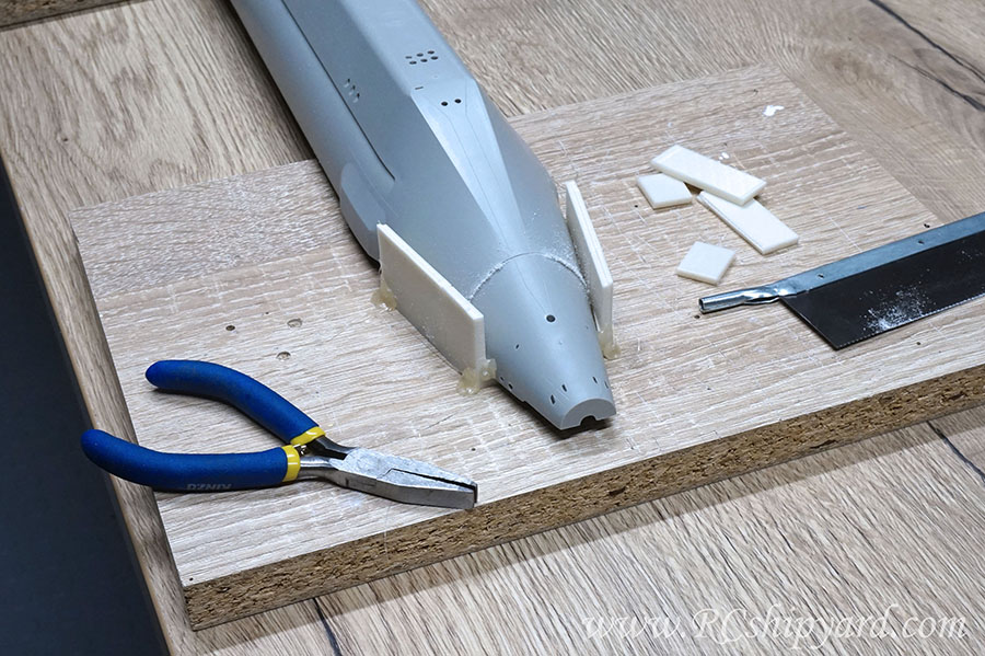
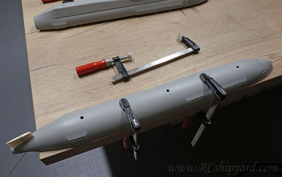
    After successfully removing one of the stern diving planes, I thought that it might be a good idea to explain in detail how I did it, instead of simply showing the result. All the used tools on one picture:


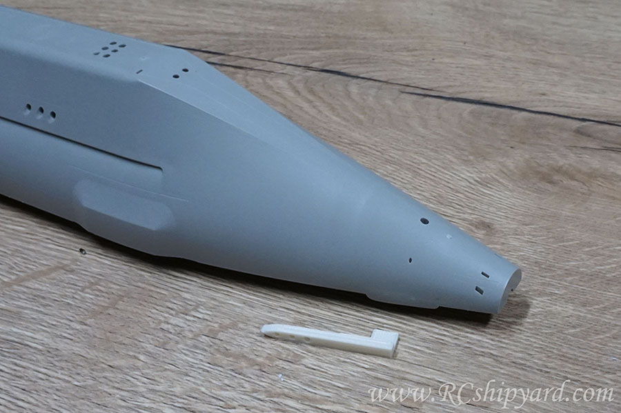
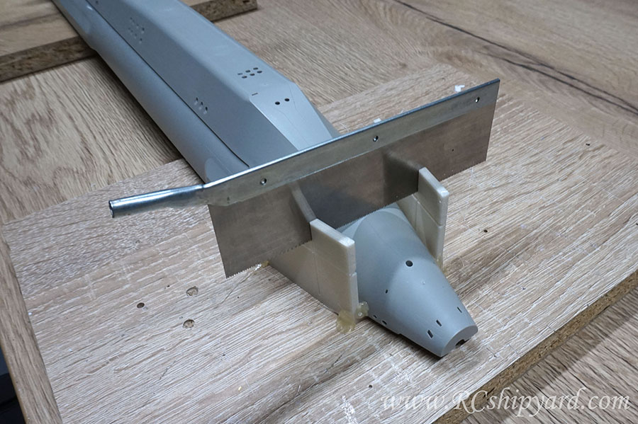
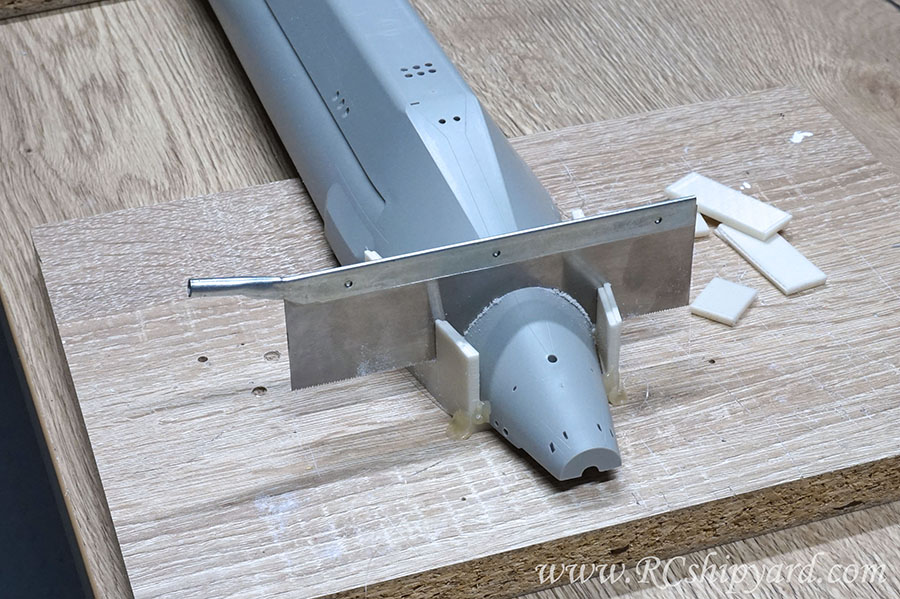
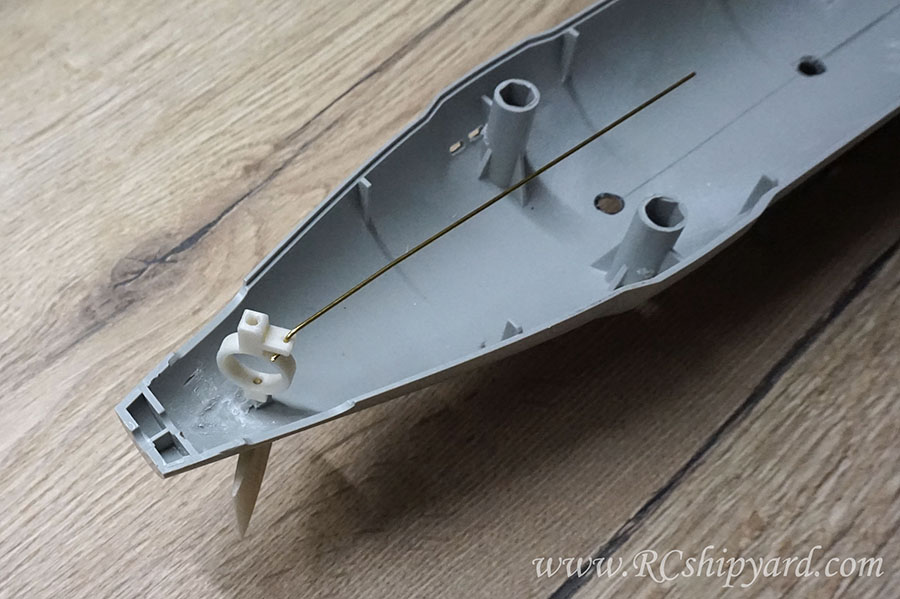
    So at first, I like to mark myself the line of cut with some margin of space from the main hull. One reason for this is because the cutting discs are fixed to the cutting bit with a screw and I don’t want that screw to scratch the hulls surface. I usually use a simple ruler for that:


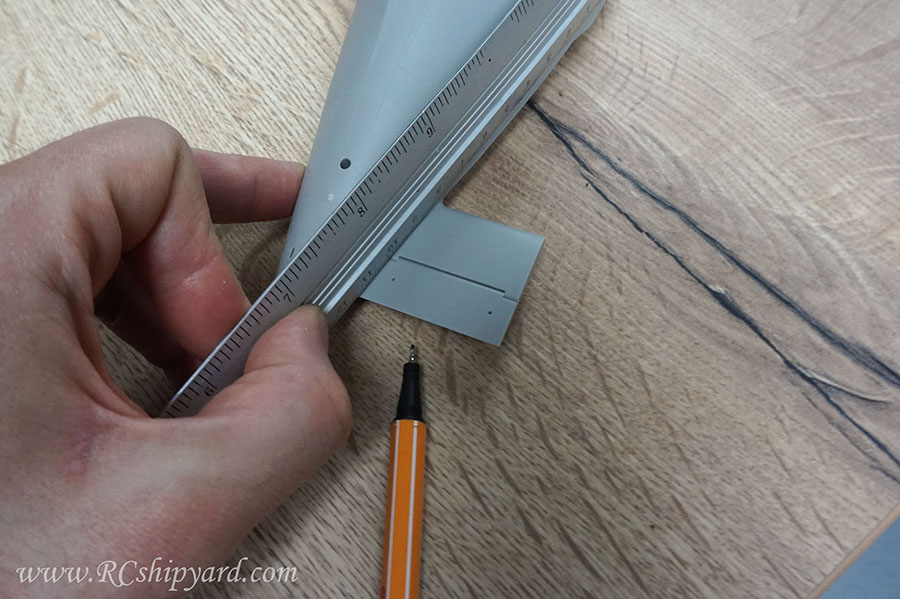
    I end up with an straight line which differs in thickness, but that really doesn’t matter, as the cutting disc itself is thicker than the line.


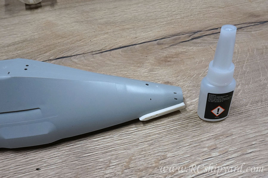
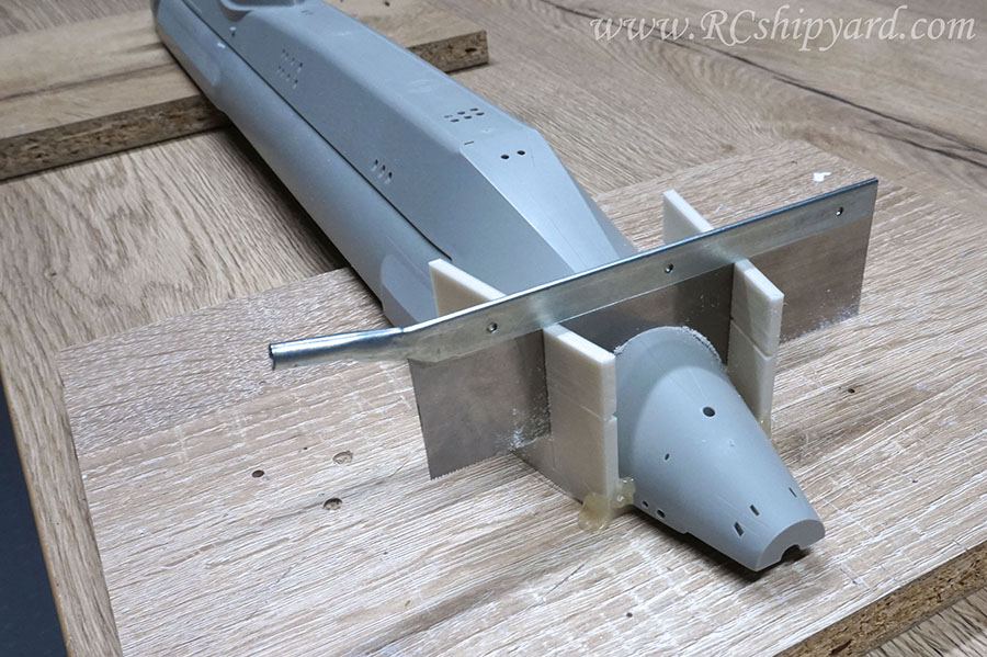
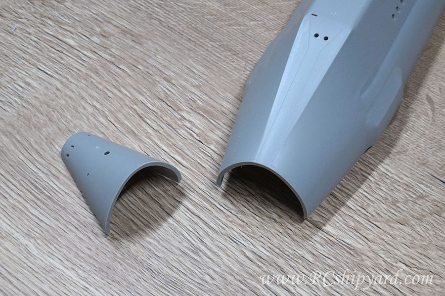
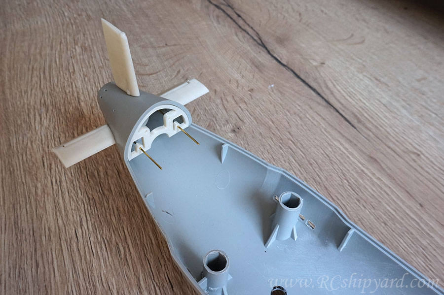
    The cut looks rough, but it has to look like this as the plastic melts from a high speed Proxxon cut – even at it’s lowest speed setting of 4000 RPM. However because of the margin of space between the hull and the line of cut, the melted plastic has lot’s space to cool down without damaging the hull (that's the second reason for drawing that line a bit further from the hull):


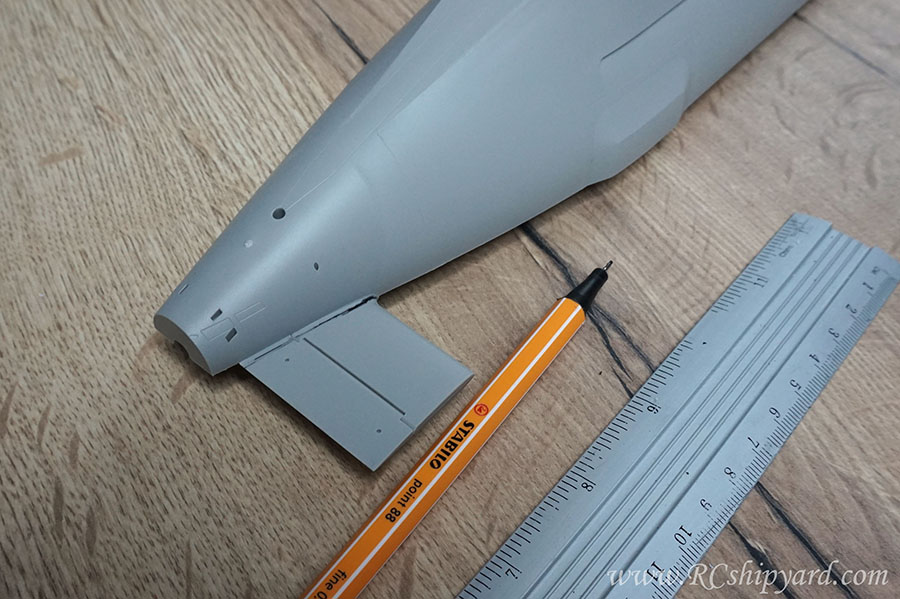
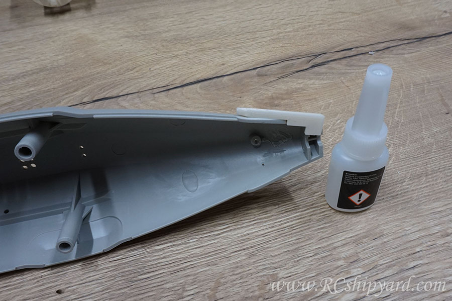
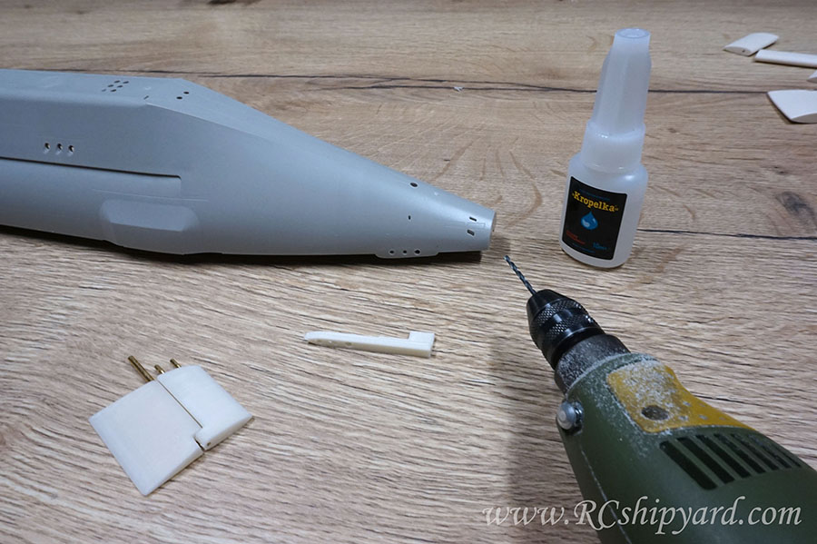
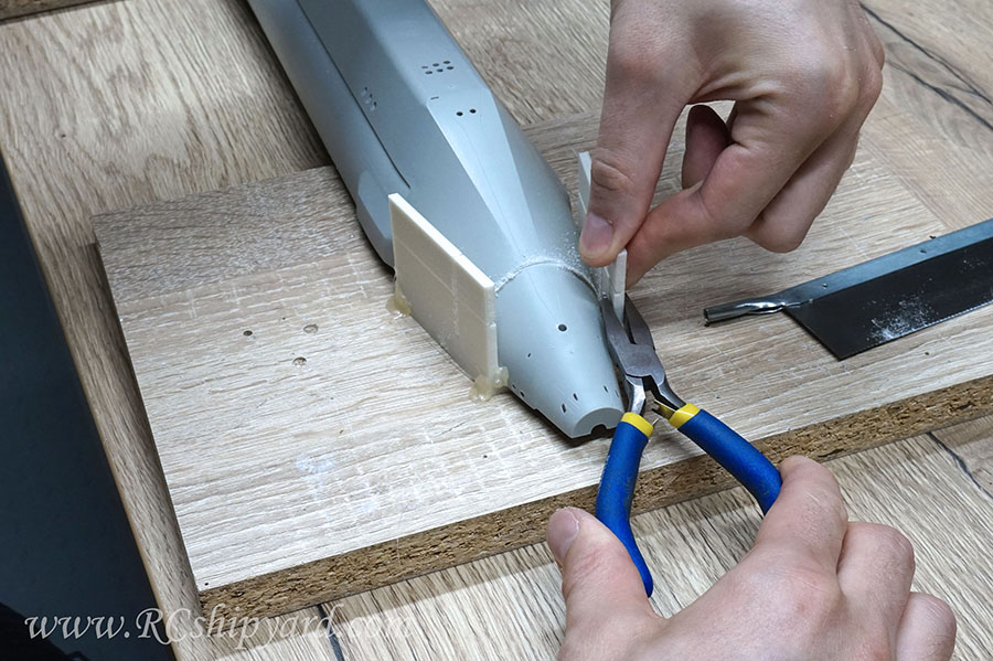
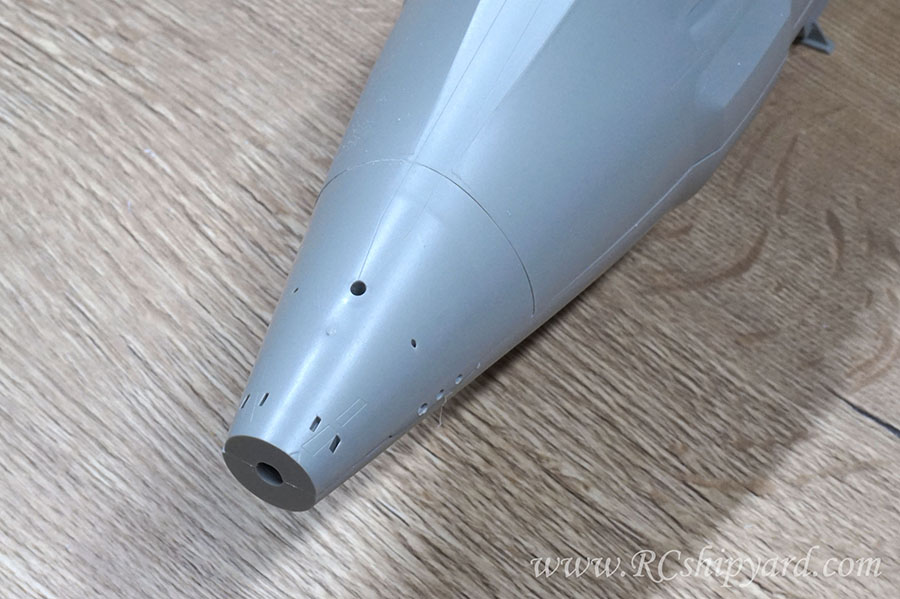
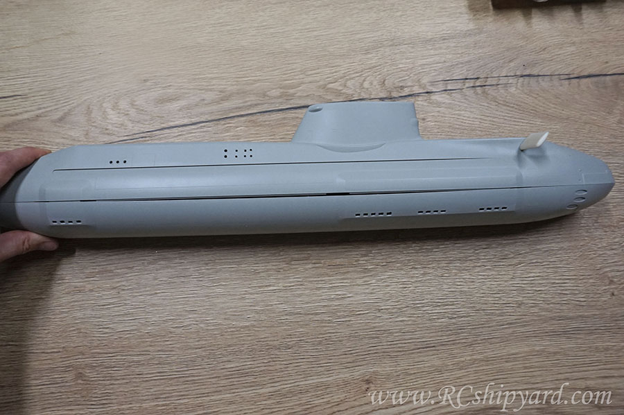
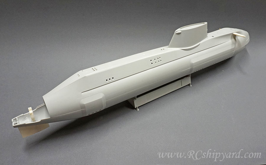
    After removing the melted plastic with bare hands, as it simply cracks off and of course after some sanding with 3 grades of sanding paper – I end up with a very nice surface finish.


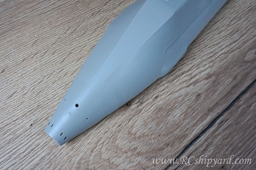
    Hard to believe there were any diving planes there in the first place, right?


    More soon!
    My knowledge base and blog:
    www.RCshipyard.com
  • salmon
    Treasurer
    • Jul 2011
    • 2327

    #2
    Jakub, I am really looking forward to your build on this!
    If you can cut, drill, saw, hit things and swear a lot, you're well on the way to building a working model sub.

    Comment

    • redboat219
      Member
      • Jan 2005
      • 519

      #3
      Jakub,
      will you be using your standard WTC with water pump and bag ballast system or your new vented tank?

      -Romel

      Comment

      • Jakub
        Member
        • May 2021
        • 34

        #4
        Hey Thomas!
        Thanks! I'm very happy then!

        Hi there Romel,
        For the 50mm WTCs I'll stick with the bladder systems, just this WTC will be a new improved version (Version 3) with the pitch controller and a magnetic on/off switch build in. Also sorry for no responding on the FB messenger, but you caught me while doing some Christmas grocery shopping and I simply forgot to reply later.

        And on the battlefield:

        For me, the next natural step was to develop a new set of dive planes and slightly large rudders – especially the bottom one for better manoeuvrability during surface runs. The trick with the dive plane was that I wanted them split – like my design in the Trumpeter Seawolf conversion. The shape of the dive planes is identical as the original ones, but I did change their proportions – the control surface has been enlarged while the non movable part of the dive plane has been shrunken. I did develop the new set of bow planes too, as the original ones are in my opinion to fragile to convert them for operational ones.


        The designed planes and rudders have been 3d printed of course. They do fit the hull nicely. Installing the lower and upper rudder will be fairly easy as there are holes already in the hull for them already – so I have just glued in some brass bearings in them and the slide the rudders shafts in.
        However there’s a different story with the new dive planes, as there are no mounting points for them in the hull. Something had to be done about that…


        I wanted to make the process of installing the stern dive planes as easy as it could be – not only for myself, but also for others who will be willing to convert this model. So I’ve designed a left and right drilling template, which fits the hull of the Astute. The templates allow for a perfect alignment of both – left and right plane with as little effort as possible. It helps to drill aligned holes for the control surface shaft in cone shaped structure of the stern.


        The template can only fit in one way and needs to be glued in temporarily to the hull with a small drop of cyano. There will be no visible marks after the glue and breaking off the template after it’s been used, as the glue only has contact with the surfaces which will be hidden in the further process of the model assembly: This means the side part of the hull, where the diving planes go…


        …and the line of assembly of the two hull parts, which obviously will be covered by the lower half of the hull:


        From this point it was just quick and simple drilling without any worries.


        The idea is to end up with 3 holes placed identically on two sides of the hull– two pairs securing the non movable part of the dive plane and the third pair one for the shaft of the control surface.


        The new set of diving planers and rudders installed and the old plastic ones laying on the workbench for comparison. The fit is good and the fix feels solid.


        And of course the bow planes comparison:
        My knowledge base and blog:
        www.RCshipyard.com

        Comment

        • Jakub
          Member
          • May 2021
          • 34

          #5
          This thread needs some catching up to do:

          I have designed and printed out a a guide rail for a very thin saw (0.3mm - about 0.013"). The guide rail has been designed to fit the Astute's upper hull shape.
          My plan is to achieve an easy access to the WTC and separating the hull piece with the stern dive planes/rudders from the rest of the upper hull will greatly help with that. The guide rail has been glued together with the hull and firmly in place with hot glue. Hot glue is great when you need to glue something temporary as with smooth surfaces it doesn't leave any marks after removal.


          The slot for the saw is only 0.38mm - about 0.015" and that allows for a very steady cut, but...


          ...sadly the cutting depth of the saw is not enough to get the job done in one cut.


          So the guide rail was designed in such a way that when you reach the limit of the saw you can break off it's top parts. The lower parts of the rail should be grabbed with flat pliers to secure them from accidental breaking off, but after that it's just simple to grab each upper piece with ones fingers to break them off.


          Now the guide rail is much shorter and allows to finish the job with the saw.


          And what's important the saw goes exactly in the same space.


          That allowed me to achieve a clean and straight surface of the cut


          The line of cut is barely visible now and I'm pretty sure it won't be visible at all when painted black.


          Looks good.


          Up next the cradle supports for the 50mm WTC, so it's some CNC time.
          Last edited by Jakub; 01-06-2022, 09:45 PM.
          My knowledge base and blog:
          www.RCshipyard.com

          Comment

          • wlambing
            SubCommittee Member
            • Feb 2003
            • 843

            #6
            Nice!! Great idea, Jakub!!

            Comment

            • thor
              SubCommittee Member
              • Feb 2009
              • 1453

              #7
              Brilliant work!
              Regards,

              Matt

              Comment

              • bob_eissler
                SubCommittee Member
                • Aug 2005
                • 331

                #8
                Nice planes and rudder conversion, you have done some work there. Are you going to sell them or make them available? I would like to have a set.

                Comment

                • redboat219
                  Member
                  • Jan 2005
                  • 519

                  #9
                  Originally posted by bob_eissler View Post
                  Nice planes and rudder conversion, you have done some work there. Are you going to sell them or make them available? I would like to have a set.
                  Would like a set too.

                  Comment

                  • Jakub
                    Member
                    • May 2021
                    • 34

                    #10
                    Thanks guys. They will be available, but better wait a little. There are some neat parts coming out of my CNC machine today, I just need to photograph them.
                    My knowledge base and blog:
                    www.RCshipyard.com

                    Comment

                    • DrScoles
                      Junior Member
                      • Jun 2021
                      • 30

                      #11
                      Did your two halves seat well? Mine have about a 3mm gap in the middle. I wanted a passive fit that was seated the whole way. Ended up using a brass tab and a button head bolt to squeeze them together.

                      Comment

                      • redboat219
                        Member
                        • Jan 2005
                        • 519

                        #12
                        Originally posted by DrScoles View Post
                        Did your two halves seat well? Mine have about a 3mm gap in the middle. I wanted a passive fit that was seated the whole way. Ended up using a brass tab and a button head bolt to squeeze them together.
                        Can you post a photo of how you did it, in case mine has a warp I'll know how to fix it.

                        Comment

                        • Jakub
                          Member
                          • May 2021
                          • 34

                          #13
                          Nice timing with mentioning the gap, as it was something I've noticed and luckily did manage to deal with during the weekend. Instructions at the end of this post.

                          At first, I did push further my work with the stern dive planes and rudders setup.


                          Classic solution for a lower ruder - a 3 mm shaft will go through the center.


                          And the last fit before gluing it all together, or at least that's what I was planning before noticing the gap mentioned earlier....


                          I did work on the pushrod for the bow dive planes too. The bow planes planes will be operated by the same servo as the stern planes. Of course the length of the model allows for a longer WTC with additional front servo for bow planes only, but I with a model of this size one good quality servo is enough. Plus I love it when my solutions are universal - like switching the WTCs between the models without the need of trim a change.


                          And of course as you guys mentioned before - I 've noticed that terrible gap too...


                          It was rather easy to determine which of the halfs is bent - In my case it's the lower part.


                          My solution to this was to fit the lower hull with clamps to the flat surface and heat the hull up with a normal hairdryer. Not one of those industrial heaters used on construction sites, just a plain heater. I did heat it up, then let it rest, then again and the cycle went for quite a few times. After that I left the hull fitted with clamps in place for 24hours.


                          And the final result. It's just the top part placed on the lower one - no screws, no force. I'm fairly happy with the result, but I do observe the model as I wonder can it "warp" back into it's original state.
                          My knowledge base and blog:
                          www.RCshipyard.com

                          Comment

                          • redboat219
                            Member
                            • Jan 2005
                            • 519

                            #14
                            Bit wary on using a hair dryer, might just use hot water on mine if the need arises. Successfully used hot water to straighten the bowed deck of my 1/48 Swift boat.

                            Plan to clamp it down like you did and pour boiling hot water over the hull.

                            Also, I think one needs to add some stops to the sides of the hull when using the hot air or water to prevent the hull from bulging out sideways.

                            Comment

                            • Jakub
                              Member
                              • May 2021
                              • 34

                              #15
                              Originally posted by redboat219 View Post
                              Bit wary on using a hair dryer, might just use hot water on mine if the need arises.(...)
                              Of course, it's important to be cautious when using a source of heat, but you do have lots of elements like the model part frames or that crappy boat stand to check how much you can heat the plastic up. You would be surprised how HOT it had to be to finally loosen up the banana shape. In my opinion hot water will not be enough, but please let me know - I'm simply curious.


                              Originally posted by redboat219 View Post
                              Also, I think one needs to add some stops to the sides of the hull when using the hot air or water to prevent the hull from bulging out sideways.
                              My thought at first too, but then it was impossible to see and control the gap between the hull and the table, so in the end I decided to simply work on the edge of the table - that way I was able avoid the bulging.
                              Last edited by Jakub; 01-13-2022, 06:16 PM.
                              My knowledge base and blog:
                              www.RCshipyard.com

                              Comment

                              Working...
                              X