KRICK's VIIB 1:60 - trying to make something nice out of it.

Collapse
X
 
  • Filter
  • Time
  • Show
Clear All
new posts
  • Jakub
    Member
    • May 2021
    • 34

    #16
    Originally posted by scott t View Post
    Very nice.
    Thanks!

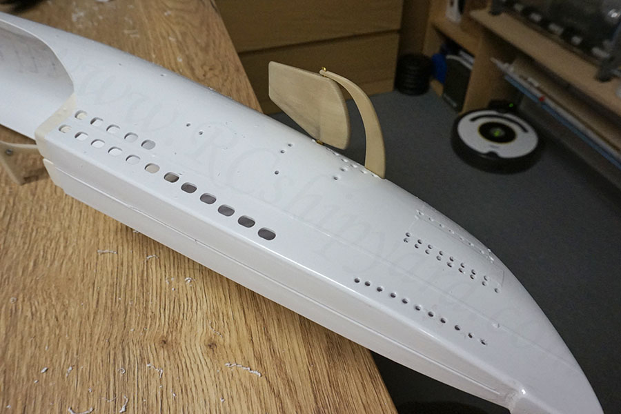
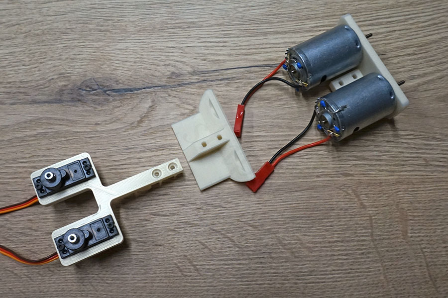
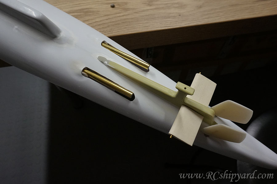
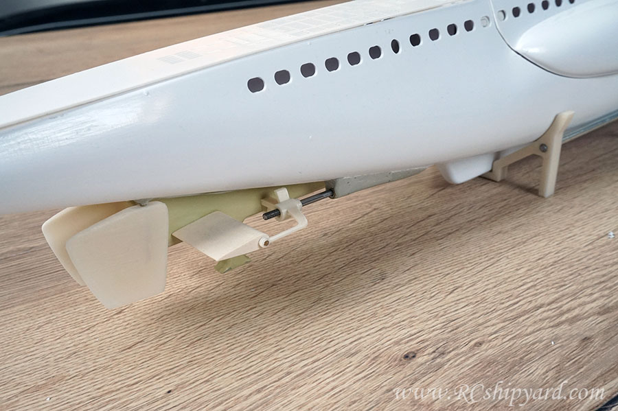
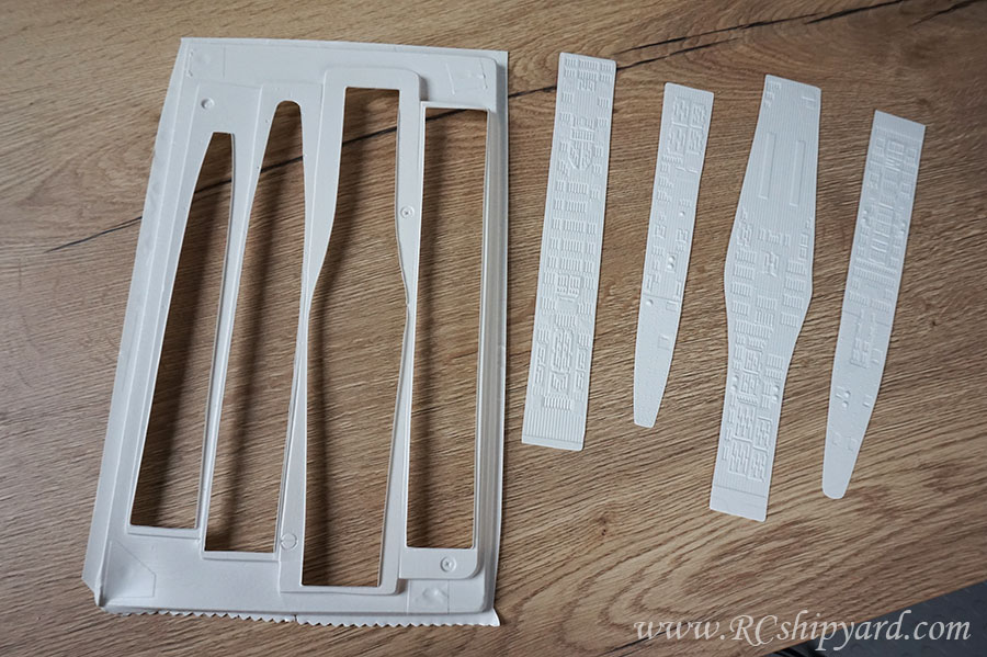
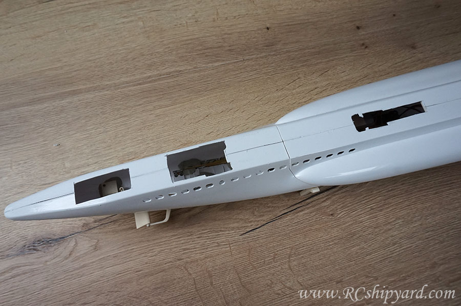
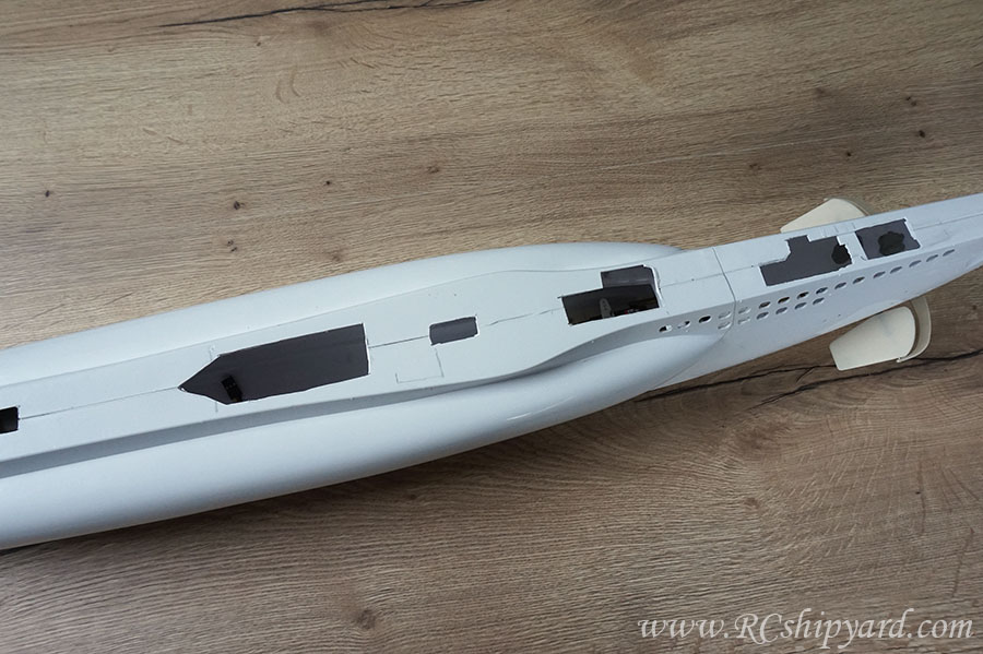
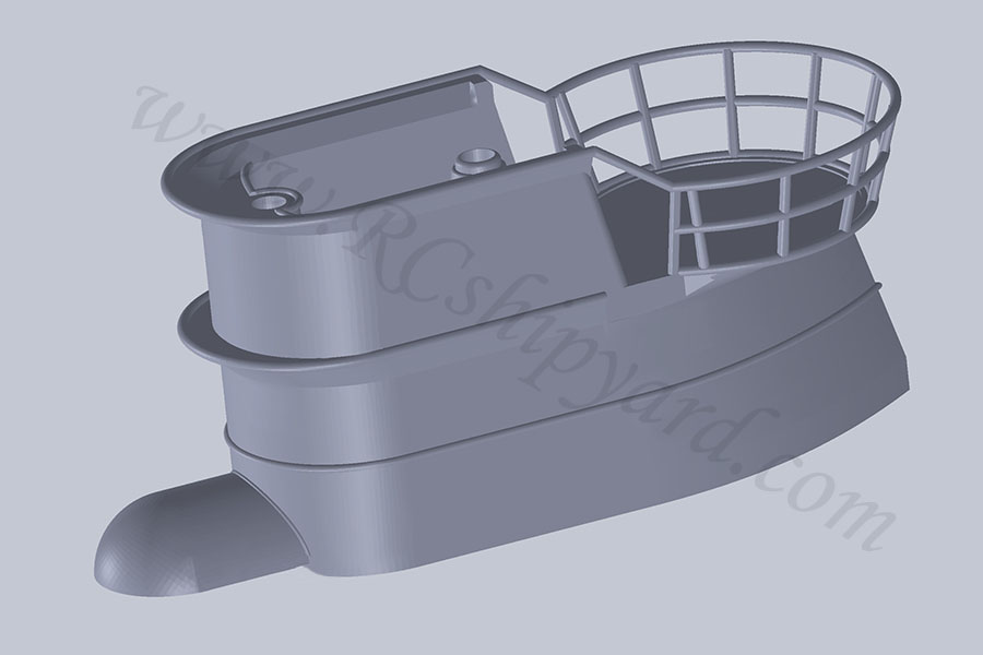
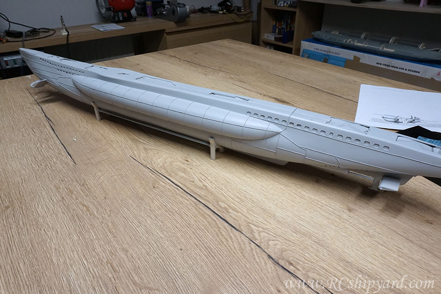
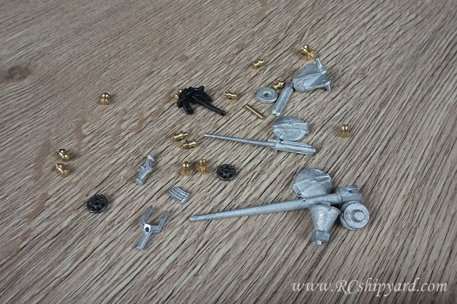
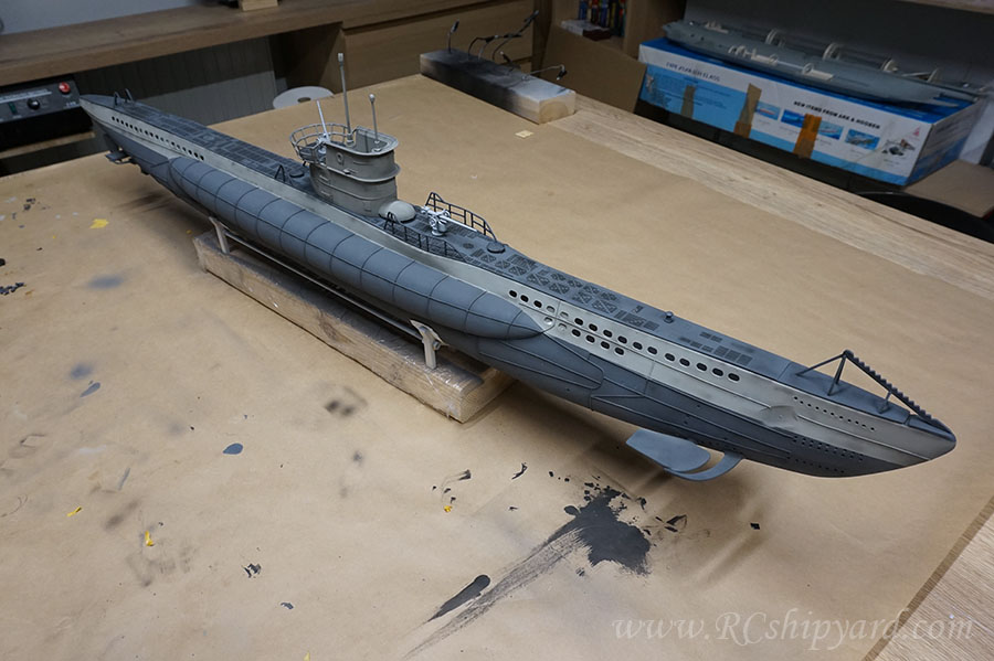
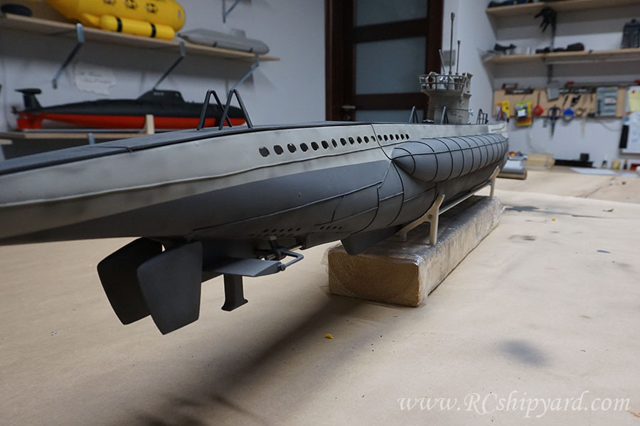
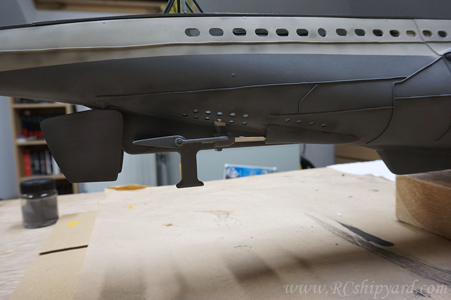
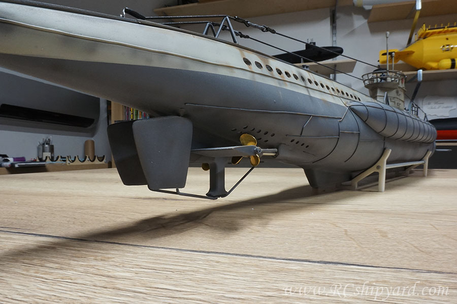
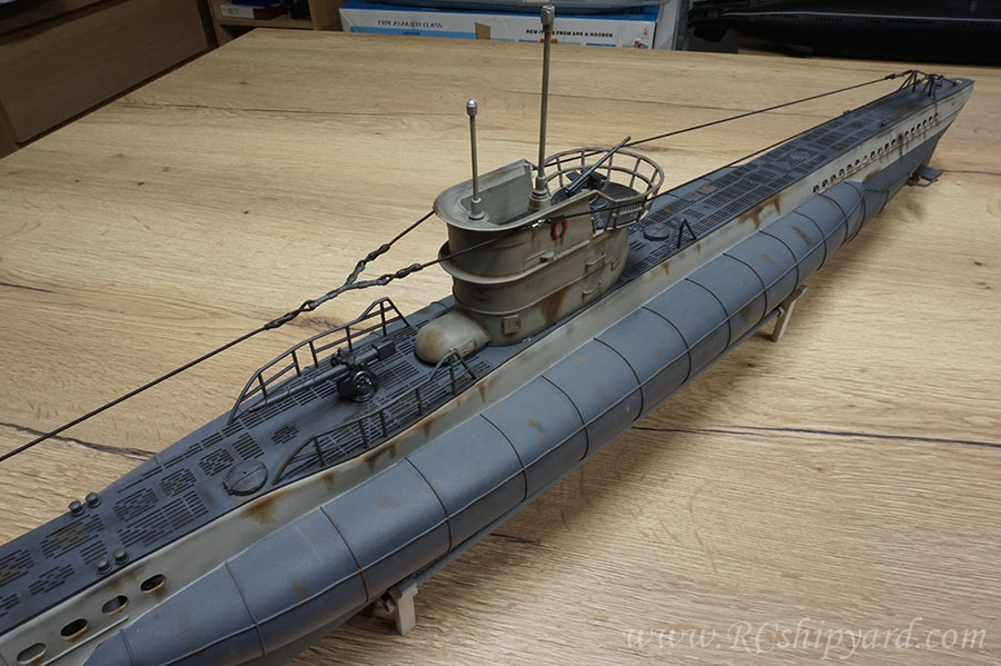
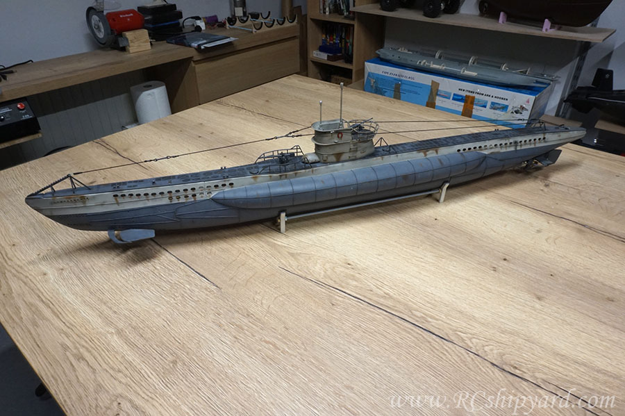
    And some further progress. With the bow planes it's a similar situation as with the stern planes - the ones provided by the manufacturer are simply to primitive for me, so I'll make myself a new set
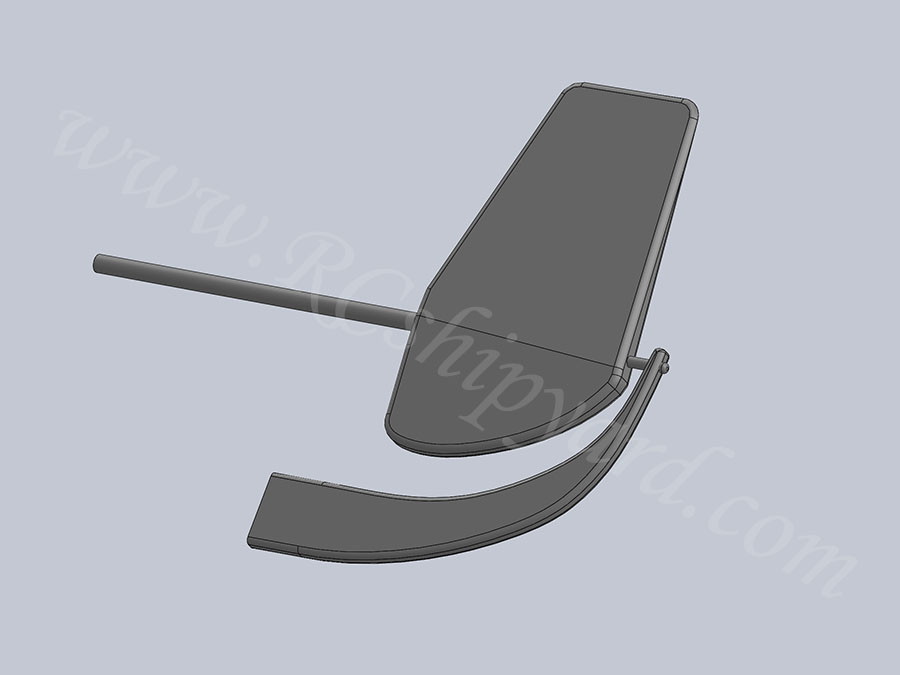
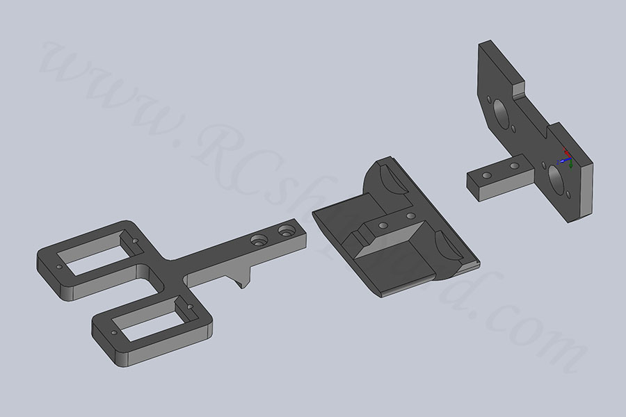
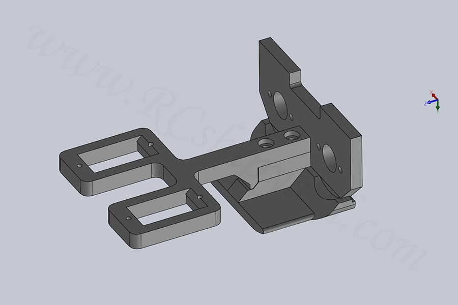
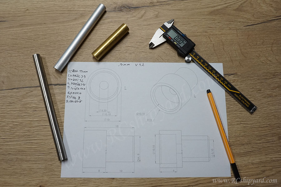
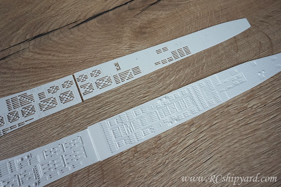
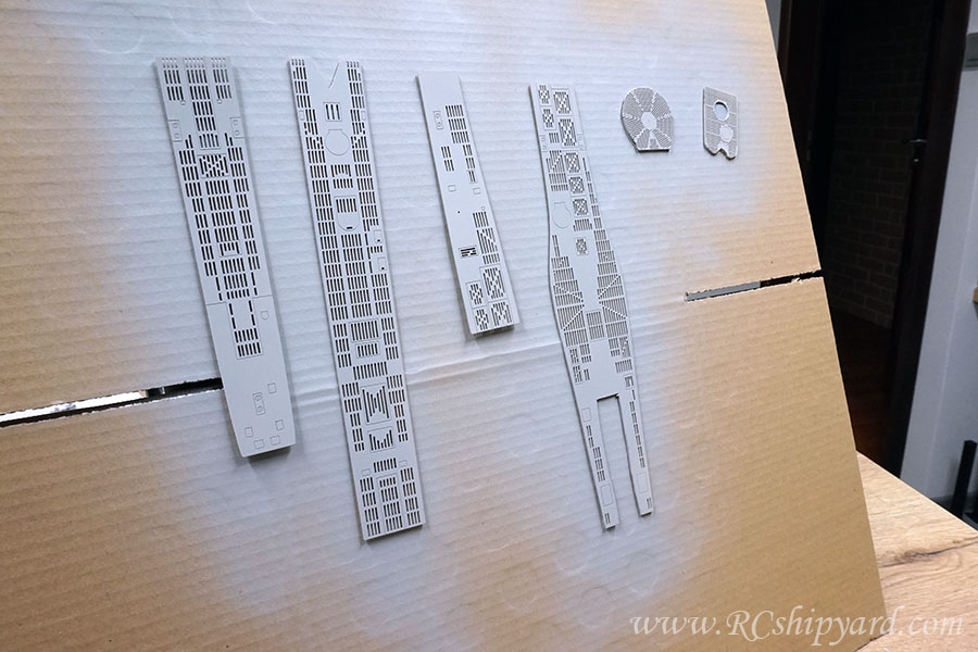
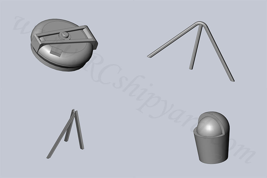
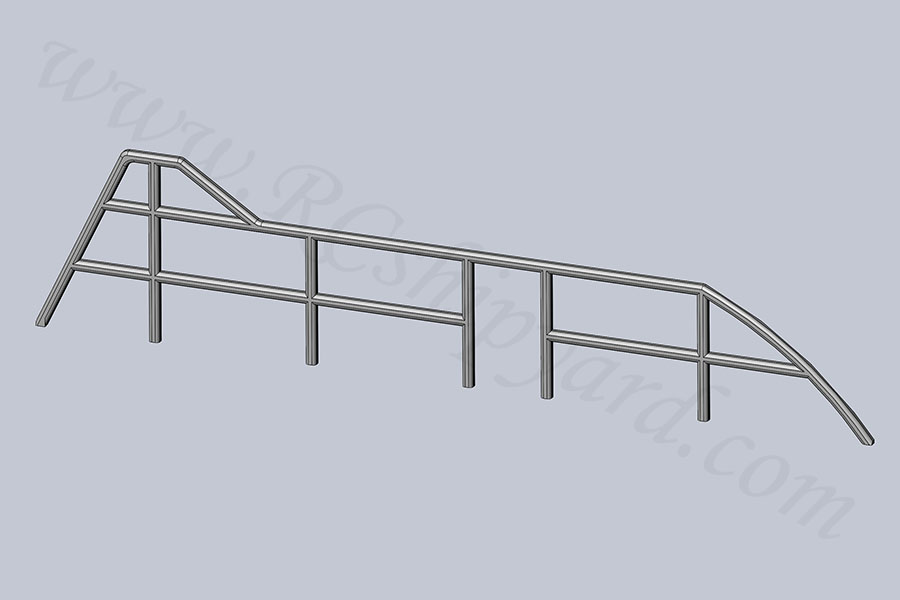
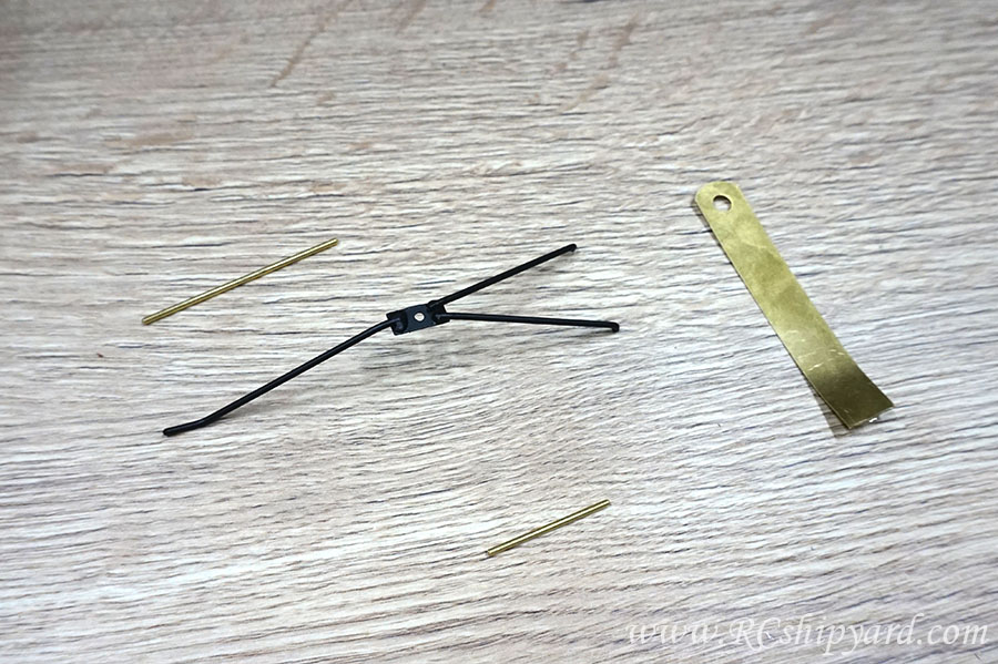
    A quick design:


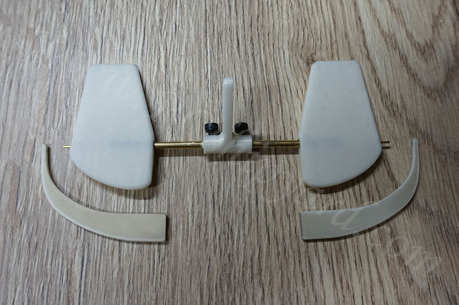
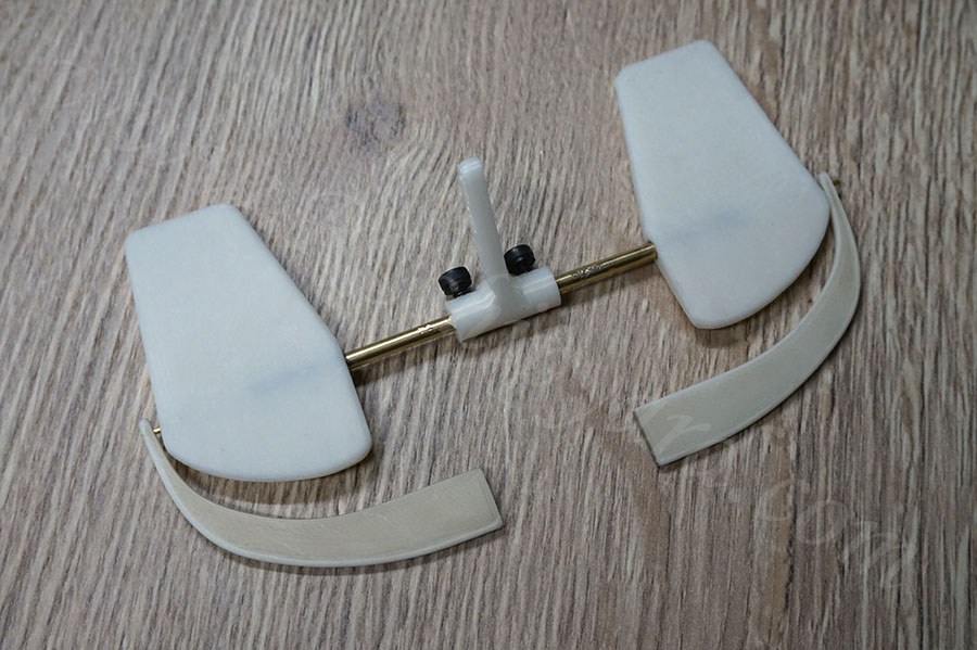
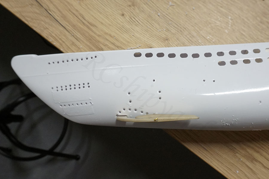
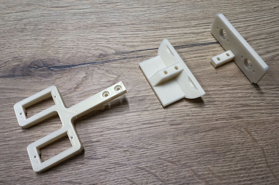
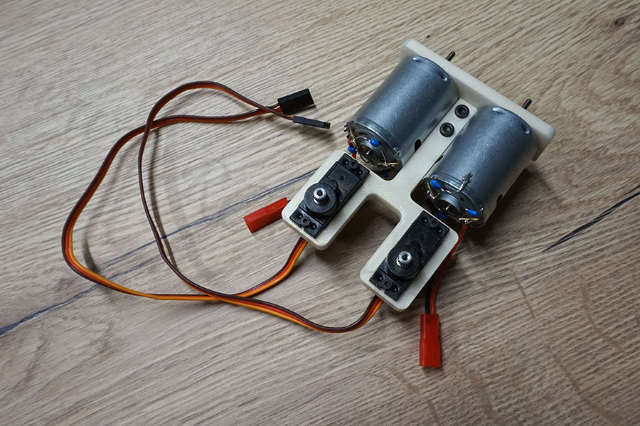
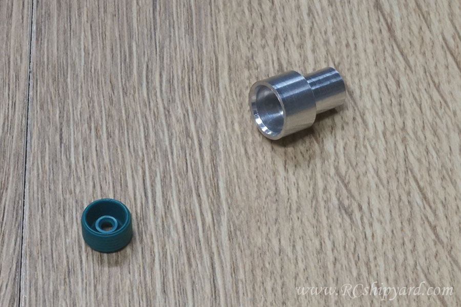
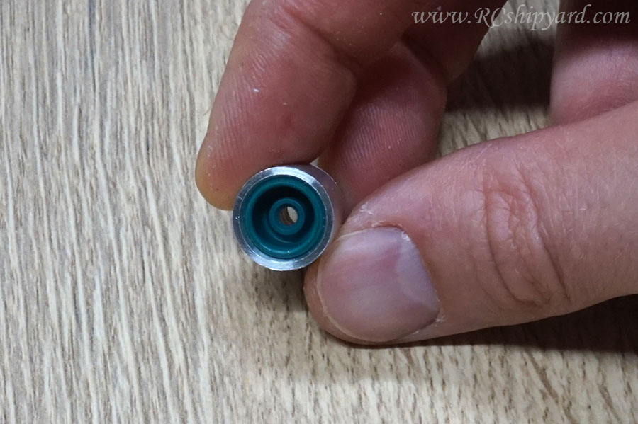
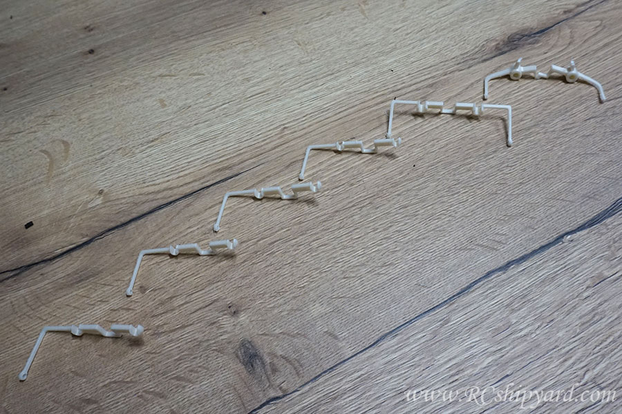
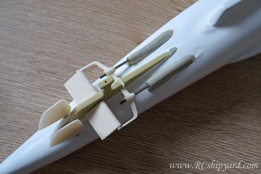
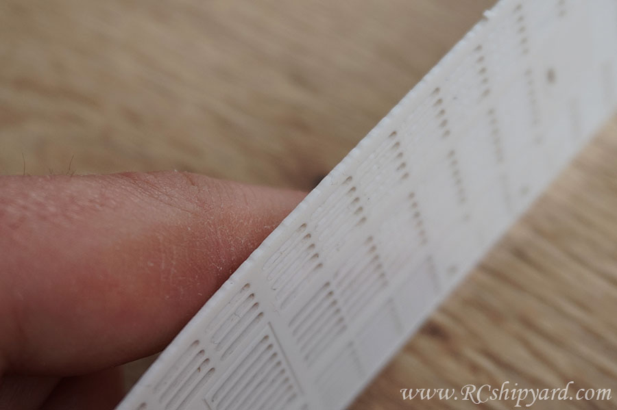
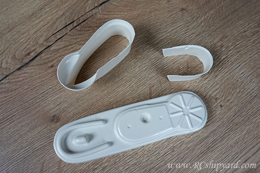
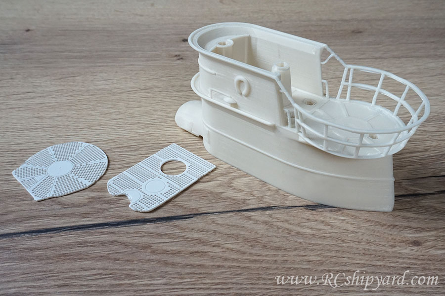
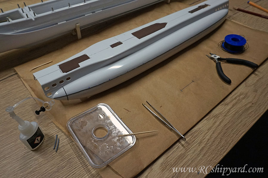
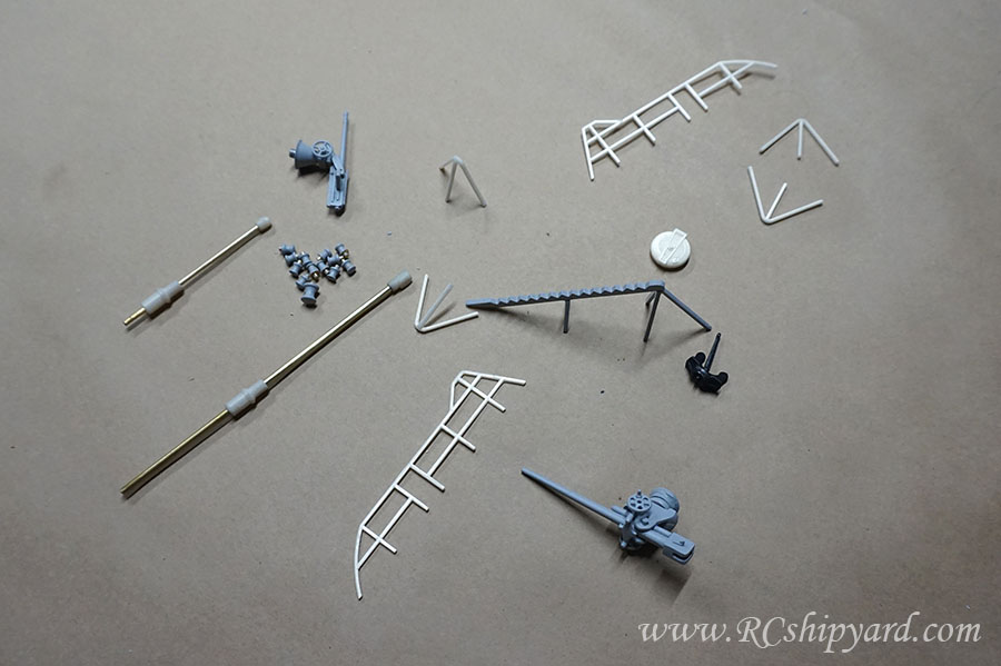
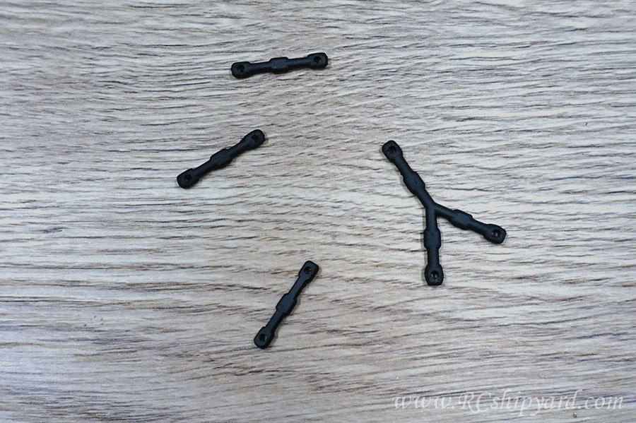
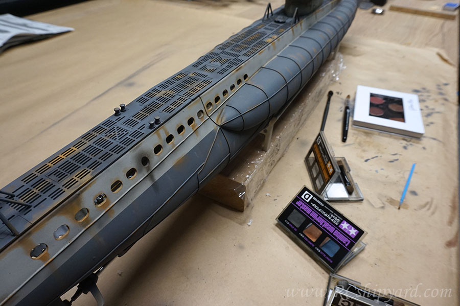
    and the final part ready for assembly, this time I used a rotary tumbler to smooth the parts out. The only disadvantage of that is that the parts have to be cleaned quite thorough:


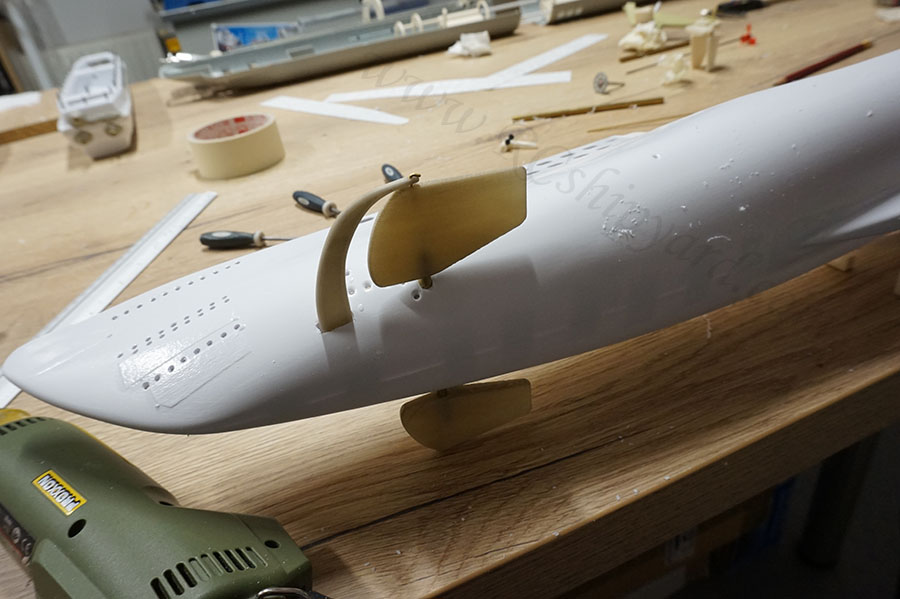
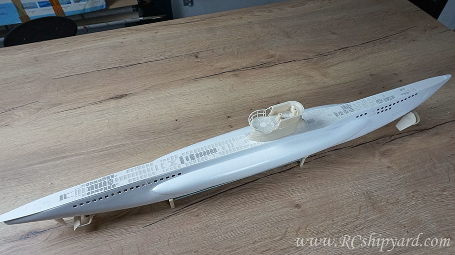
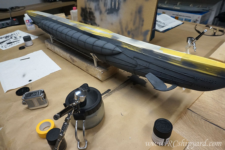
    The planes are slightly larger then they should be, as I want some decent manoeuvrability, which type VII models usually lack.
    My knowledge base and blog:
    www.RCshipyard.com

    Comment

    • Jakub
      Member
      • May 2021
      • 34

      #17
      There are some national holidays currently in Poland and the weather was not at best again, so the work goes further:

      Getting ready to mount the bow planes, double checking everything etc.


      The planes still need some cleaning, huh.


      The alignment seems decent.


      The motor block.
      Krick's idea is to use two motors with a direct drive. That seems alright, as I was never happy with gearboxes splitting the power from one motor into two separate shafts. The mounting plate for the motors is pretty alright too, but I made myself a new - thicker one:


      It would work alright, but at some point I had a much better idea... I wanted a better flexibility - in case something breaks. Now, when using the original motor block (or mine thicker one), after gluing in the motor board into the WTC (as the manual says) I would end up with a very limited access to screws holding the motors in place. It would be very difficult to replace the motors in case they break. I wanted to be able to remove the whole motor block from the top, plus some mounting slots for the stern servos would be nice too. So back to the drawing board:

      My idea was to make 3 separate parts, servo block which obviously holds the servos, motor block which will keep the motors in place and the middle part will be the only non removable part glued to the bottom of the WTC.


      They all combine into one multi purpose block, which is easy to disassembly and removal from the top by using the Allen key:


      Printing time again:


      everything fits in place:


      and the assembly time:


      seems that it fits the WTC quite alright:
      My knowledge base and blog:
      www.RCshipyard.com

      Comment

      • scott t
        Member
        • Feb 2003
        • 879

        #18
        Two thumbs up.

        Comment

        • Jakub
          Member
          • May 2021
          • 34

          #19
          Originally posted by scott t View Post
          Two thumbs up.
          Thanks!

          The motto for today is THIS MODELS BIGGEST ENEMY IS THE PLAN AND THE MANUAL! SERIOUSLY!

          A first major mistake. I did glue the two parts of the WTC at the wrong line after all! I left to much material on the upper part. The manual was very vague about how much material is waste and I left to much. With the current setup I was simply not able to close the hull with the screws and caps in place. Bummers.

          So I had reopen it. Tough work, but manageable only because I used epoxy instead of my ABS glue - exactly in case of such a scenario.


          Then the thing was glued together again, still using epoxy.


          At this point I took a look at the shafts provided by Krick. They're a waste of money. They're even a waste of brass and plastic. The hole in one of the shafts was not centred (brass part). Shafts have no seals or gaskets at the ends and NO BEARINGS. No Teflon or at least plastic ones. The inner (steel?) shaft is only 2mm in diameter while the inner diameter of the brass tube is 4.6mm. That's a 1.3mm gap in each side inside. Very poor quality.


          So here I'm trying to arrange everything in my head, also at this point I have ordered and received two new shafts with brass props. Both shafts are 5mm shafts with a 3mm stainless steel rods. The thicknes of the brass is 0.8mm. That leaves a gap of a 0.2 on each side. This should be possible to seal with thick grease and an oring at the end only, but in case it would not be enough, I will have a plan B prepared. I will explain it at the end of this post.


          Now this photo is quite important for whoever will make this model in the future. Kricks manual is wrong, kricks plan is wrong too. If you want the shafts to be horizontal with the boat don't follow the manual or plan. I have followed it at first and had to seal the first pair of shaft holes with epoxy putty. New and proper holes in the WTC need to be placed much lower - like mines on the photo.


          And the bow part of the WTC. At this point I have decided to avoid the manual and I will not follow it any more. You can see the pushrod for the bow dive planes and the two brass tubes. One tube is for the snorkel while the other is the water inlet.
          My model will have a different ballast system than the Kricks idea. Maybe it's a similar one, maybe not. I'm not going to look into that crappy manual any more.


          Still I'm slowly being happy how this thing starts to look. Mostly how well a sanded Tamiya putty matches all the parts together:


          Plan B in case the thick grease and an o-ring will be not enough. As always a design and choice of material first. I though I'll go with brass, but in the end I decided that, I'll give stainless steel a try:


          Half an hour work on the lathe:


          And here's the idea, well known to some for sure:


          It's worth to remember that simmerings have two sides - this side should always go towards the bigger pressure, as I will place this part inside the WTC I will have to flip the simmering.


          If the shaft will leak, I'll simply glue this thing to the shaft inside the WTC like this.


          Yay!
          My knowledge base and blog:
          www.RCshipyard.com

          Comment

          • Jakub
            Member
            • May 2021
            • 34

            #20
            Update!

            So I was quite eager to check is the WTC watertight. After one hour in the tub there was no water inside, also no bubbles while blowing air into the WTC by the silicon tube. That's a good sign I guess. What worries me is the amount of weight I had to put on the model to keep it underwater - 2.5kg (5.5pounds), of course the WTC is completely empty, yet still that's a quite a lot of ballast for a model of this size.


            Here you can see the evolution process of designing and printing the shafts/dive planes stabilization element (left to right). It's impossible to take precise measurements from the model with such a complicated shape, so hence the trial and error method. Still I was able to achieve it quite fast, 6 prototypes and I was done. The element was hard to design because it has to be collinear with 5 different axis: two shafts, two dive planes and the fin in the middle of the stern. The last prototype had a funny bug. It was possible to attach the element to the model but impossible to detach, hence it had to be broken upon removal and redesign for the final time. Maybe I'm wrong but it seems, that Krick didn't even care to include his own parts for making this element... Quite sad.


            Further works on the stern, the slots in the hull for the twin shafts have been filled with a two part epoxy putty and sanded down. Quite long, but a rather pleasant work. On the photo you can also see already attached the final stage of the stabilization element which evolution has been presented above. It's function is purely decorative as no real forces will work upon it, but still important as it's a very distinctive part of German IIWW boats. Still a little gap between that part and the hull, but I'll fill it with epoxy putty on a later stage.


            The shape of the Kricks stern is not to realistic. To keep the shafts vertical I had sacrifice some of the realism here - the place where the shafts leave the hull has a different size and shape than the original vessel. Still, I did my best and the priority was a proper operation of the boat. I guess I'll just smoothen the connections/transitions with some Tamiya putty and that's the best what I can do.


            I did cut out the thermoformed decks included with the kit....


            ... but in the internet I found milled ones dedicated for the VIIB type. So I ordered them. Stern decks comparison:


            Middle decks:


            Bow decks:


            Quality difference is enormous, the after market decks are really better, yet they'll require some extra work too. Sadly it's quite easy to notice that one side of the decks has a rather rugged surface. Not a real problem, but at that price the CAM program for the mill could have been made better.


            While having decks with cut out slots I don't have to worry about air getting trapped under the decks any more - very good thing. But still I had to cut out the holes in the hull beneath the new decks. Some decks will be glued permanently to the hull while others will be magnetic and removable allowing to service the model wet mechanics:


            A rather weird shapes, right?


            Only because I wanted to make sure I'll not end up with a line of cut in the middle of the deck's slots.


            It finally looks like a submarine, right? Just why that d*mn deck is to long if it's dedicated for the 1:60 Krick!
            My knowledge base and blog:
            www.RCshipyard.com

            Comment

            • Ralph --- SSBN 598
              Junior Member
              • Oct 2012
              • 1417

              #21
              You boat at 1/60 scale is about 43.4" long and has a beam of about 4.1".

              5 pounds of ballast weight is not much.

              Trimming will take pace when the boat is complete.
              Now for testing you use what ever it take s to get the boat under water for the leak testing.

              When the boat is complete and ready for trimming, All added ballast weight should be as low in the hull as you can get it.
              Under the cylinder is best.
              Add ballast until the boat submerges with the ballast tank full of water.
              Empty and fill the ballast tank with air a few times to get the ballast tank and ballast system neutral on it's own.
              Then add or remove weight to get the submerged level.
              Move the weight slowly forward or rearward to get the boat level.

              Then surface the boat and see where the boat sits tot he waterline.

              You submarine has 2 center of gravity that can not cross during the dive or surfacing operations.
              They will come close to each other and if too close the boat will roll on it's side for a moment and then hopefully back upright.

              Getting the center of gravity correct requires both to be level in all operations.
              Sumberged is harder to get than surfaced but more important.

              I have several boats and the amount of weight needed in each is different.
              Wet huli is less than dry hull but harder to get CG right.

              So while you check for leaks, add as much weight as needed and not worry if it's 5 pounds or 10 pounds.
              You are testing just the hull.
              You need weight to get teh hull down and that requires adding more to represent the upper hull that is not in stalled.

              By the way, Nice work

              Comment

              • steveuk
                Junior Member
                • Oct 2005
                • 467

                #22
                Well done Jakub. I am astounded how fast you have put this all together and made such neat custom parts too. I am not sure if your replacement deck has corrected the position of the tower. I know that the standard Krick kit has the tower too far forward, and no compass housing. Krick took a few liberties with this kit. But if you know what is wrong with it the major flaws can be put right.

                Comment

                • Jakub
                  Member
                  • May 2021
                  • 34

                  #23
                  Hey Ralph, Thanks for the hints! I'm pretty sure that I'll manage, this little thing is not my first rodeo

                  Hello Steve, I've seen your thread and I took myself the liberty to fix some of the problems, before they would appear in my model. The new deck moves the tower towards the stern by about 35mm, it already looks better, but it's not as far as it should be IMHO. To fix that, I would have to cut some new slots in front of the tower and cover some of the ones in the back to gain about 10mm more - in my opinion these additional 10mm are not worth the effort. For me Krick is only the training ground before the assembly of the Type XXI by Robbe, which is also an ABS hull design.

                  Speaking about the tower:


                  Elements for the tower supplied by Krick since the beginning seemed really primitive to me. The effort required to make something not laughable from those would be enormous and the effect would still be moderate at best.


                  So of course my idea was to design it in the CAD software and then print it. Then, after the initial sanding adding some of the details like the ladder steps and emblems. As the tower of the VIIB is rather simple, it was a good time to try hitting two birds with the same stone and also test the capabilities of my 3d printer. Normally I would print the rails as flat elements and then bend them over a heat source into the desired shape. Yet, in this particular scenario even if it would be to much for the printer and the rails would end up as spaghetti, I would have simply cut them off and attach new ones made with my trusty old method.


                  After few more changes in design, the final model ended up looking like this:


                  Here I tried how some of the details will look attached: the emblem and the decks which I had to cut in two and then cut their sizes down by hand to make them fit my tower. I still need to do some flooding holes and/or vents and service hatches.


                  In the end the decks fit, still they'll require some sanding, but I'm sure that in the final stage they'll fit in nice and snugly. It's worth noticing that even when using such technology as 3d printing, you'll get a better effect when using several separate elements rather then print everything at once. Maybe some exceptions apply to the liquid resin printers, but these are not on my horizon currently. As I said before the rails printed without the supports were a big experiment for me - as a user of a "classic" FDM printer, but the printer managed to make those quite decently. Some of them look "bendy" and maybe their lower edge will require some sanding or corrections with a heat air stations, but in the end I'm very pleased with both the design - at least compared to the Krick elements and the printer "torture test".


                  This is how the tower will look on the hull. Of course just placed there for the moment as it will be finished and painted as a separate element. But before the paint work it's time to deal with that ugly flat hull...


                  Less Krick in my own Krick with each step, right?
                  My knowledge base and blog:
                  www.RCshipyard.com

                  Comment

                  • Jakub
                    Member
                    • May 2021
                    • 34

                    #24
                    I had to stay at home for Saturday so the work continues. A lot of it actually.

                    I don't like the flat surface hulls, so I had to do something with the Krick's hull:

                    A pen with a ruler, cyanoacrylate glue and lots of Kynar wire...


                    After few hours of work starboard was finished.


                    Few more hours and the port side was finished too.


                    And the top view, with the way to wide and bulky saddle tanks. I saw that Steveuk modified those and it does make a great difference, but I decided that I'll leave them as they are. Partially from being lazy and partially to leave at least some of the Krick's spirit in this model...


                    Now, if the weather will be alright, I'll put some primer on the parts in the evening.
                    My knowledge base and blog:
                    www.RCshipyard.com

                    Comment

                    • Jakub
                      Member
                      • May 2021
                      • 34

                      #25
                      The weather was kind enough to let me coat the model with a few layers of spray primer. The darker spots on the hull are shadows from a big old larch which grows on my land. The paint has been distributed even and I managed to cover every detail and nook.


                      The decks, tower and few of the other smaller details have been covered with the primer too.


                      After the initial drying I did inspect it and I think it looks quite alright. The spray primer is "Tamiya super fine". Till now I was using mostly the "Chaos black" primer, but sadly they most likely changed something in their paint's composition, as since a while it's a worse and not worth the money anymore. Of course that's my private opinion.


                      Finally it's not looking like a cheap ABS made toy


                      Now I'll leave it for a few days to dry completely and do some work on the details which I'll need to assemble or design. Depending on the one quality of those delivered with the KIT.
                      My knowledge base and blog:
                      www.RCshipyard.com

                      Comment

                      • Jakub
                        Member
                        • May 2021
                        • 34

                        #26
                        Painting! Finally!

                        So first I had to paint the "under deck" in black, it will give the grey deck a better visual 3 dimensional structure. Also the black colour will mask the places where deck wasn't cut. It's a bit of an illusion - I've once read about that in some book about movie effects and I want to try it.


                        A little cameo in my own building thread thanks to my wife and her trusty Iphone. Of course I'm applying the grey colour. Loooot's of it. 2x 23ml Tamiya jars have left the building.


                        Flat grey finally applied:


                        and some shading. I do shading by mixing the final colour with some black colour, additionally reducing the airbrush pressure.


                        Removing the old tape and applying new one - to cover the job already done. This is how it looks for me to get ready for applying the last colour:


                        The same black "under deck" illusion was applied to the tower too.


                        Krick has included some details made from lead. They seem nice, require lots of sanding for sure, but I'll use them. Still lot's of other details are missing. Especially the rails and the periscopes.


                        Not a big deal as always to design the missing parts. In the lower left you can see the observation periscope, still missing is the attack periscope, which will also hide the snorkel for the ballast system.


                        And of course the missing rail - the one around the deck gun. It will be 3d printed as semicircle flat object - with a mirror of itself copy. Then the plan was to glue them together to make a round railing and shape it over a heat source to a correct shape of the hull. so to make two of the rails I'll need 4 elements.


                        Applying primer and getting ready to paint
                        My knowledge base and blog:
                        www.RCshipyard.com

                        Comment

                        • Jakub
                          Member
                          • May 2021
                          • 34

                          #27
                          Things got slower recently due to the amount of work before the vacations, but as I'm taking the whole August as a time off I'm planning to finish this thing in the upcoming days.

                          After taking the masking tape off I was fairly happy with the result. I've also applied the first weathering shadows right away after the main paint. It's essential for me to do it right away as I make my shadows by mixing the base colours with 10-20% of black colour, so I need to use the exactly same base colours (colour - thinner ratio). Still, the deck gun and the flak gun are only covered with primer and require further work. But they will be painted with slightly different paint than the deck.


                          Bow view:


                          Stern view:


                          Rudders and dive plane stabilizers have been painted separately. They've now rejoined the hull. The stabilizers had to be fixed in place with some epoxy, it's joint will be painted at a later stage.


                          At this point I have also made the missing details - the rudder stabilizers/protectors. I've decided to made them out of brass and solder them manually, instead of a 3d print, as this element may easily hit the bottom of the pond.


                          Line details:


                          At last! The weathering!
                          I use mainly Tamiya weathering KITs plus some make up KITs. I apply them all by a sponge.


                          As the model will have contact with water, all the weathering will have to be covered with a thick layer of varnish. This will tone down all the weathering colours so it's worth to remember to make the weathering a bit more bright and vivid at this stage of the work


                          And Finally...
                          adding the missing guns, lines and all the other details including the complicated rudder system


                          I'm extremely happy with the end result of the railing around the deck gun, as it was a big experiment to print those flat as two hemispherical elements each (each railing - four elements in total) and then gluing them together.


                          At this stage I consider the model exterior as finished and I'll be moving to the missing internal systems. Time to find some battery cells and make a battery pack!
                          My knowledge base and blog:
                          www.RCshipyard.com

                          Comment

                          • wlambing
                            SubCommittee Member
                            • Feb 2003
                            • 843

                            #28
                            Best looking Krick I've ever seen! Very Well Done!

                            Comment

                            • scott t
                              Member
                              • Feb 2003
                              • 879

                              #29
                              Very nice!

                              Comment

                              • salmon
                                Treasurer
                                • Jul 2011
                                • 2306

                                #30
                                Jakob, you kicked butt on this one! Super cool!
                                If you can cut, drill, saw, hit things and swear a lot, you're well on the way to building a working model sub.

                                Comment

                                Working...
                                X