Attention all registered users. The new forum upgrade requires you to reset your password as you logon for the first time.
To reset your password choose this option that is displayed when you attempted to login with your username: "Forgotten your password? Click here!"
You will be sent an e-mail to the address that is associated with your forum account. Follow the simple directions to reset your password.
If this is your first visit, be sure to
check out the FAQ by clicking the
link above. You may have to register
before you can post: click the register link above to proceed. To start viewing messages,
select the forum that you want to visit from the selection below.
There are also four single holes that are not paired, three on the starboard side and one on the port. They are very faint on the original image, but if you look at this pix of Boss Subfixer's fleetboat in the "Photos of a built-up Revell 1/72 Gato" thread, you can see where they are.
I have the same plan sheet that Boss Subfixer has. Please keep in mind that those three single holes on the starboard side are the location of the manhole covers for access into some of the tanks. These openings are normally fitted with covers. so to depict them accurately they should be scribed into the hull. The one on the port is the well for the negative tank flood valve. This valve opened outward, hence the reason it is recessed.
Also, keep in mind that during the war the ballast tank flood ports had the valves removed so these were open to the sea. The fuel ballast tanks had flood valves that opened inward, so these should also be scribed and not open. The normal fuel oil tanks were completely sealed and had no flood ports or valves at all. These are where the three manholes on the starboard side lead into. Finally, the safety tank flood valves (2) were also located in their own well and opened outward. The valves were located in the sides of the well and the two flood ports were located in the bottom.
I got to the links by going to Navsource and looking up the individual boats. For example, the /08/0826512 picture can be found under the SS 265 Peto page.
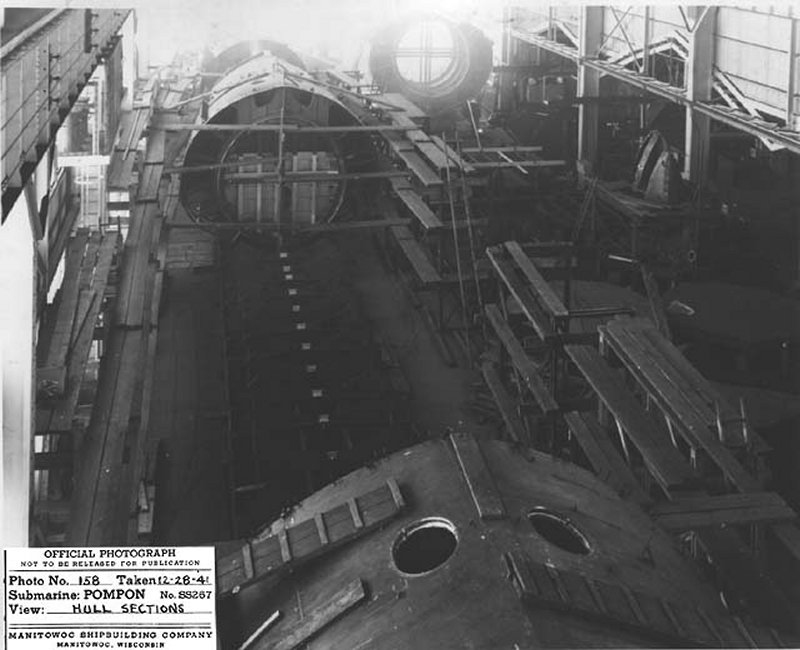
These pictures show what looks like the flood holes on the tops of the sections, but does this mean that Manitowoc built the sections upside down?
Interesting, hadn't noticed before.
I found them that way too. And yes, the description reads that the sections were upside down during part of the welding process at Manitowoc. They were then taking to the ways were they were set upright on the keel blocks and joined to gether. News to me too. And the first images I've seen of the flood holes in a fleetboat.
Sorry for the delay but the shading of the hull leaves a messy drawing that requires a lot of clean up. I have the inital transfer but it looks like everyones out done me!
OK, I see how the secret decoder ring works. Good tip, Sean. Really interesting photos, Gus. You must have spent a lot of time on Navsource to uncover these.
Through a heroic effort, Tim was able to e-mail me 3.8mb worth of .tif files that really show the shape of all the holes. This, with Scott's location drawing and Gus's description should be enough to do a credible job on the Gato. g2tiger, it wouldn't hurt to have your tracing as another reference, since the hole pattern seems to vary some between the different boats. Now I just need to know which ones are the ballast tank ports and which are the fuel ballast tank flood valves. I think these illustrations from "The Fleet Type Submarine Online" should tell the story. Good work pulling this all together everyone.
sigpic
"There are the assassins, the dealers in death. I am the Avenger!" - Captain Nemo
Sorry about the links. They're working for me so I'm not sure what the problem is. Anyway, yes those are photos from NavSource and yes I went through every photo for every sub. I didn't want to take the chance on missing something and they do add more photos from time to time so I have to check on a regular basis.
One other thing, I really recommend the drydock plan from the Cobia museum. It is expensive but it shows the location of the flood ports and EVERY other opening in the hull, the dinemsions of the openings, and what they are for. Just keep in mind it is based on the Cobia so it pertains to Electric Boat subs and not Portsmouth boats.
If someone gets some good clean templates done for the Revell flood holes, I will ask our web guy if he will make a spot where they can be downloaded right from this website.
Well here is my latest efforts.
These flood holes are drawn from tif drawings
with SS263 printed at the lower edge.
This seems to be a different drawing than the first drawing I traced.
I removed the old files and replaced them with ss263 jpg file on my home page.
I printed one out and the image still shrinks slightly in the conversion from CAD to JPG.
Anyone trying to use these will have to zoom them to the correct size by the one inch bar include in the drawing.
The tick marks in the openings are centerpoint of each arc or circle.
The widths are per the drawing not the reference tables.
Does anyone know how to work around the shrink problem?
Shrink - JPGs compress by throwing away info, might have something to do with size problem. TIFs are big but solid, tho they don't display on the web. Can you make TIFs?
PDFs might be better. Sometimes they are 1-2% smaller, sometimes not, might be worth a try. My work sells a mini PDF writer for $10 (encourages our customers to make PDFs for jobs), I am authorized by my boss to send you a free copy if it would help.


Comment