Attention all registered users. The new forum upgrade requires you to reset your password as you logon for the first time.
To reset your password choose this option that is displayed when you attempted to login with your username: "Forgotten your password? Click here!"
You will be sent an e-mail to the address that is associated with your forum account. Follow the simple directions to reset your password.
If this is your first visit, be sure to
check out the FAQ by clicking the
link above. You may have to register
before you can post: click the register link above to proceed. To start viewing messages,
select the forum that you want to visit from the selection below.
I don't have any new images to show, but I did hear from my friend and he has sent the STL files to the shop for manufacture. He said it would probably be a week, two at the outside, before they are made. The delay, I think, has been a blessing, because I have been really busy the last few weeks and it would have been hard for me to focus if the model had been built.
The parts have been made. My buddy just texted me this image of the completed parts still in the SLA printer.
I am super excited and concerned at the same time. The parts look awesome and in the lower left hand corner, you can see that the screw appears to have come out very nicely. However, the detailing on the larger parts, if present, isn’t visible in the image. I don’t know if you just can’t see it or if it isn’t there. It almost makes me wonder if the wrong parts were printed. I should know by the first part of next week since my buddy is coming to town Sunday, and is bringing the parts with him.
I will post pictures when I get them.
Well, as I suspected, the wrong parts got printed. The guy printing it forgot that we had sent him new files and printed the original design. I was pretty bummed about it at first, but then I remembered where I was when I started this adventure, before my buddy said that he could make them for me. Besides, he said that they will make the detailed one later, so now I just have an extra one to play with. And even without the detailing, it looks pretty cool.
Below is a picture that my buddy sent me of the printed model. Not shown, but already made, are the other rudder and some extra screws that the guy made because they are so small and delicate.
A close up picture of the screw and Dunce Cap is shown below. As you can see, the blades are really thin, but have pretty good detail.
I will send more pictures when I actually have the model.
UPDATE 40 – 3/13/2013
Good Morning Everyone!
I picked up the parts Sunday afternoon, and it was really a great feeling holding them. It is really rewarding to hold something you made, as you all know, since you too are modelers. My disappointment of them having made the old parts has been quickly replaced with joy and contemplation as to how best to complete the model at this point. More on that later. First, some pictures.
The first picture shows all of the parts.
The next picture shows the first three segments. I really like the way the nose came out. I had to add several cross sections in addition to the ones on the plans to get the nicely rounded shape, and I am thrilled how it turned out. You can also clearly see the attachment point for the sail on the second piece and the alignment posts on the third piece.
The next picture shows the mid-section parts. Again you can see the alignment posts. You can also see that the alignment bar didn’t get printed on the first piece on the left. I don’t know how this happened. If you look at the part in Update 4, back on November 27, 2012, the bar is there. Unfortunately, I can’t check the AutoCad files because I moved on and long since deleted the older versions.
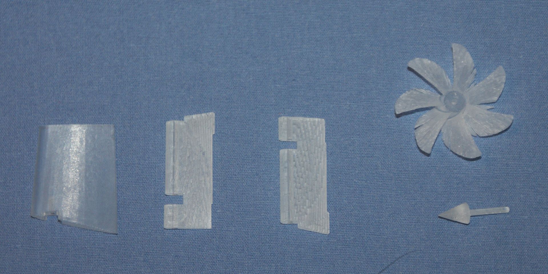
The aft sections are shown next, as are the screw, dunce cap, dive planes and one rudder. The guy that made the parts mistakenly made only one rudder. He realized his mistake and is making (or has already made) another one.
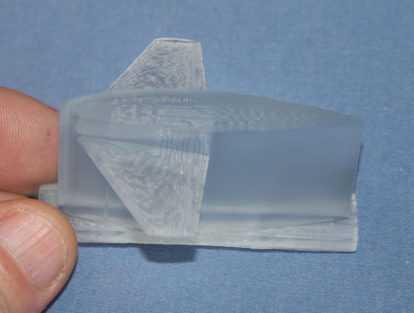
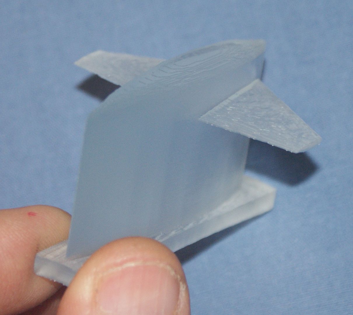
The next three pictures show the sail. Since the parts that were printed were of my initial design, the sail plane is fixed to the sail. ( The most interesting feature of the pictures, to me, is the fact that you can clearly see the layers, even though they are only 0.005†thick. The pattern it makes almost looks like grains on wood. I think this will be easily remedied with a little sanding.
Also note that the sail sides look polygonal and are not smooth. This is because I just used the cross-sections on the plans and did not add extras as I did on the nose. At first I wasn’t crazy about this, but if you look at pictures of the subs, the seams are often clearly visible.
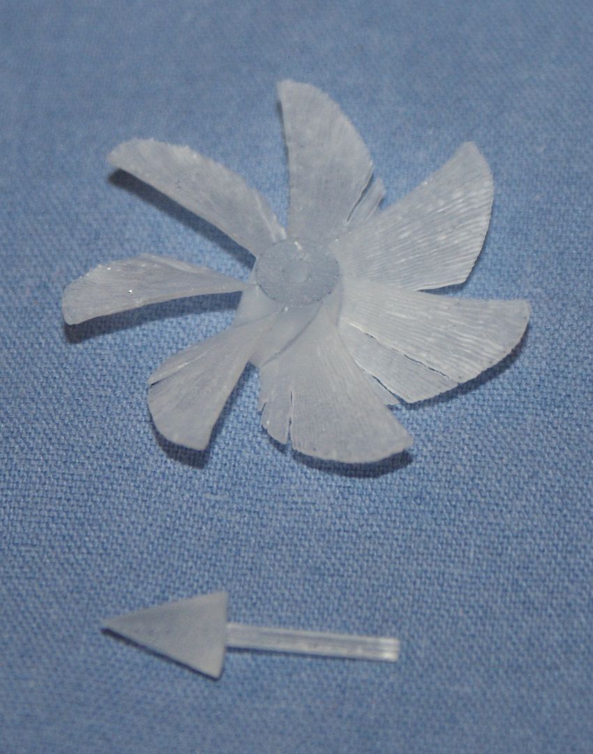
The next image shows close up shots of the one rudder, the dive planes, the screw and dunce cap, and the following image shows an even closer shot of the screw and dunce cap. With these smaller pieces, the resolution limits of the SLA printer used to make the parts starts to become apparent. The aft end of the dive planes is jagged, I think because of the way the parts were made. I am by NO means anywhere near an expert on 3D printing, but judging by the grains, it looks like the parts were made on edge. I think if they would have been made standing up, the jagged edge wouldn’t have happened.
The feathering on the leading edge of the screw blades shows that the part is right at the limit of what the SLA can accurately print. The thickness of the blades is 0.010†and you can see that this this form results in splits occurring along the layer seams. The guy that made the parts thinks that this happened during part processing and is making (or has made) a couple of extra when he prints the rudder he forgot. If I was doing it again, I would make the blade a little bit thicker, say 0.015†– 0.020â€, because even though it would be off scale, I don’t think that it would be noticeable and the extra thickness would likely eliminate the feathering. Even so, the screw, even as it is, is useable, with a little work.
An encouraging feature is the dunce cap. Note how nice and defined the point is and how round and straight the shaft is. The shaft fits neatly into the screw as planned.
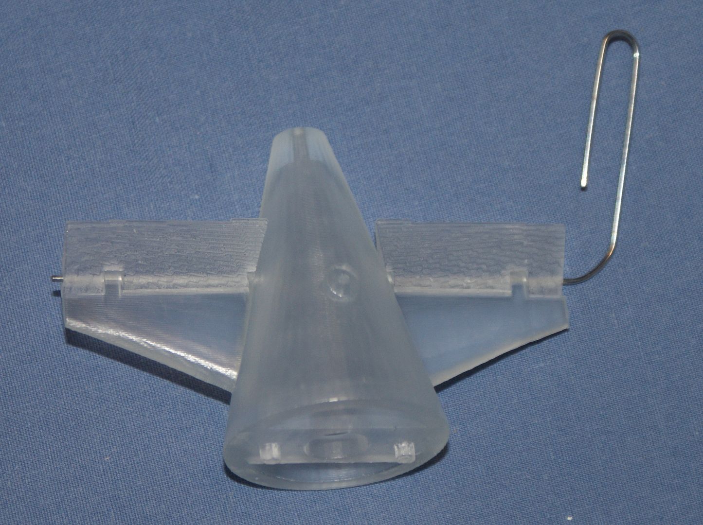
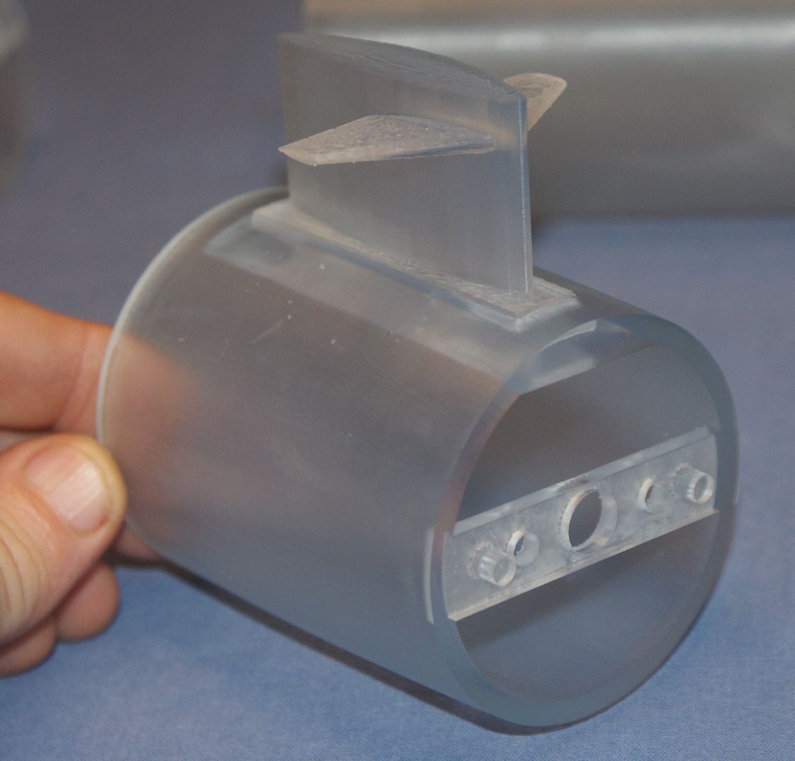
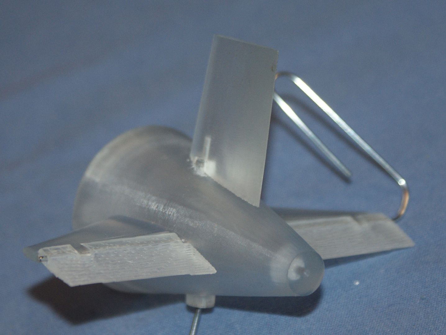
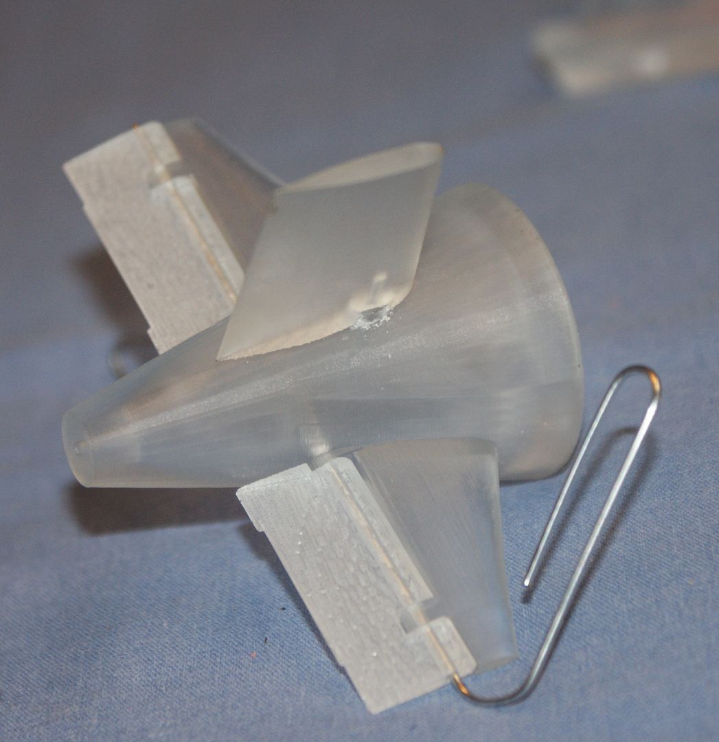
The final picture shows the dive planes temporarily attached to the hull section. The holes are nice and round and properly aligned or the paper clip would not have slid through as it did.
So, even though I am still somewhat disappointed that the detailed parts didn’t get made, I am encouraged by the way this model came out. Besides, my friend assures me that he will make the detailed ones at some point, or at least make the nose and/or sail to see how it comes out.
In the mean time I now get to build the model and since this is the first submarine I have ever built, this is the point where I need your help. My main questions at this point are related to scribing and painting.
First, with regards to scribing, I have only very limited experience scribing and would like some suggestions. Is it better to scribe the plastic itself, or apply a few coats of primer, perhaps over a coat or two of Future, and scribe that?
As for painting, as much as I agree with Sub culture that it would look pretty cool with LED lights in it, I plan on painting it, hopefully using rattle cans. I have an el cheapo spray gun, sufficient for spraying future, but not painting. Does anybody have any recommendations on what brands and colors I should use to paint it?
I’ll keep you posted as I progress.
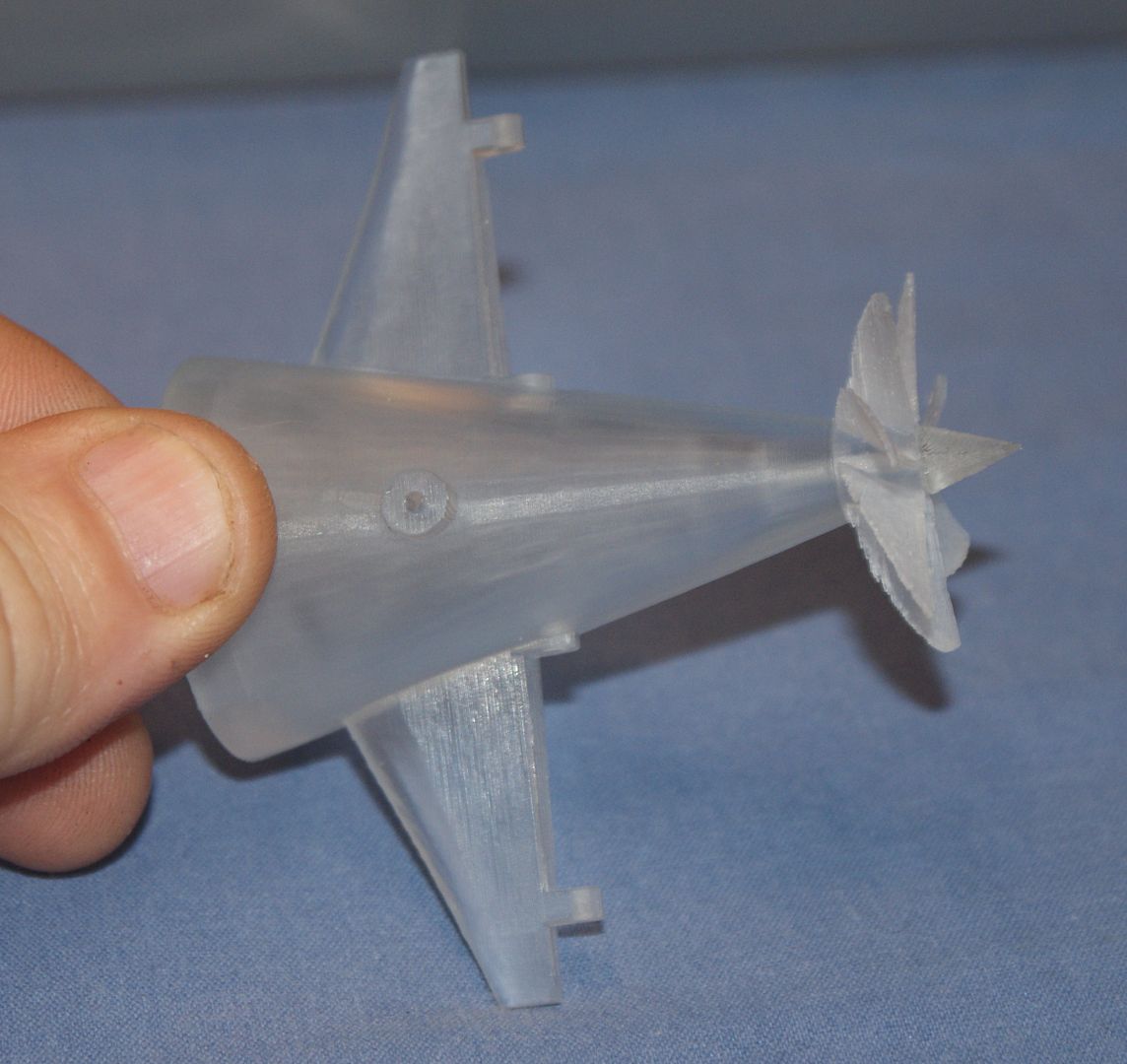
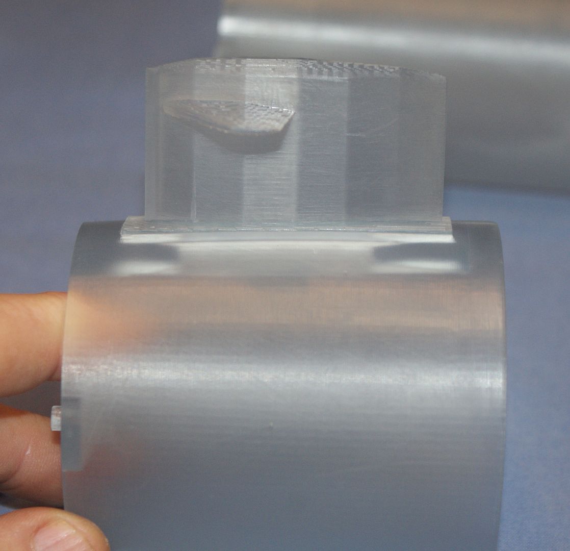
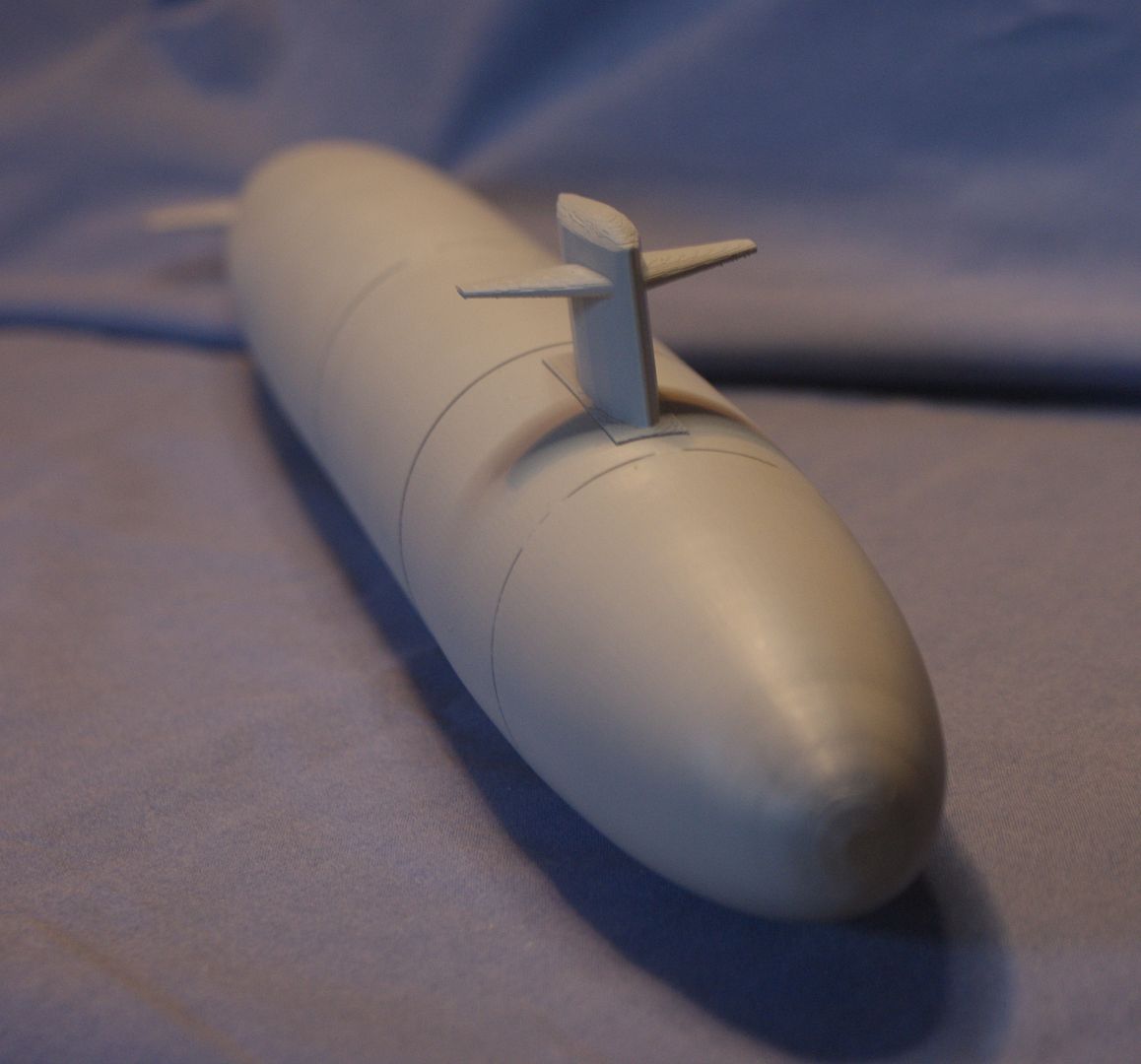
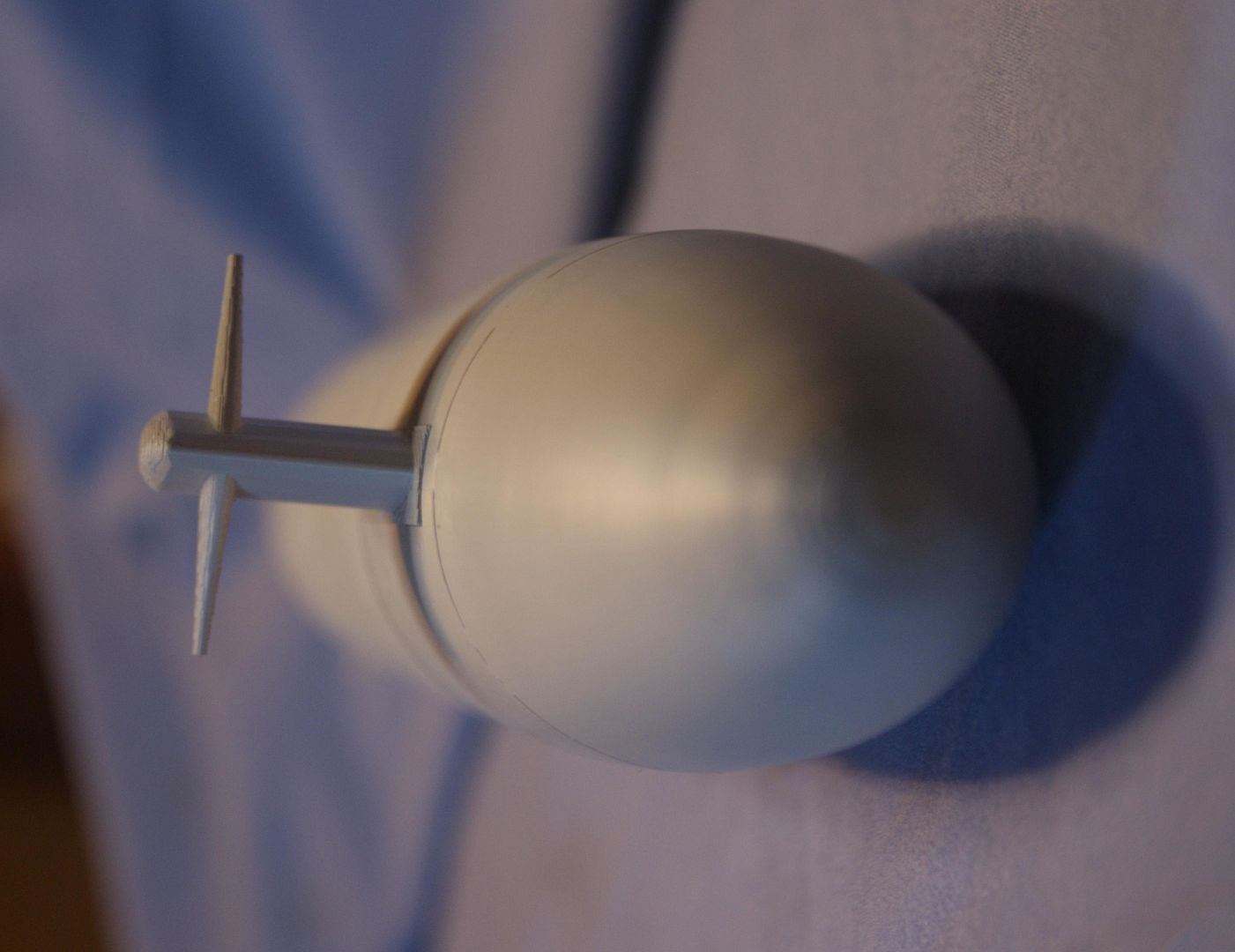
I thought I would share some more pictures of the model. The first three images show the screw and dunce cap dry assembled on the stern section. Only minor filing with a pin file was required to get it to fit properly. You can’t tell from the photos, but the screw rotates smoothly around the shaft, although it really doesn’t need to, because this is, as I said, a static model.
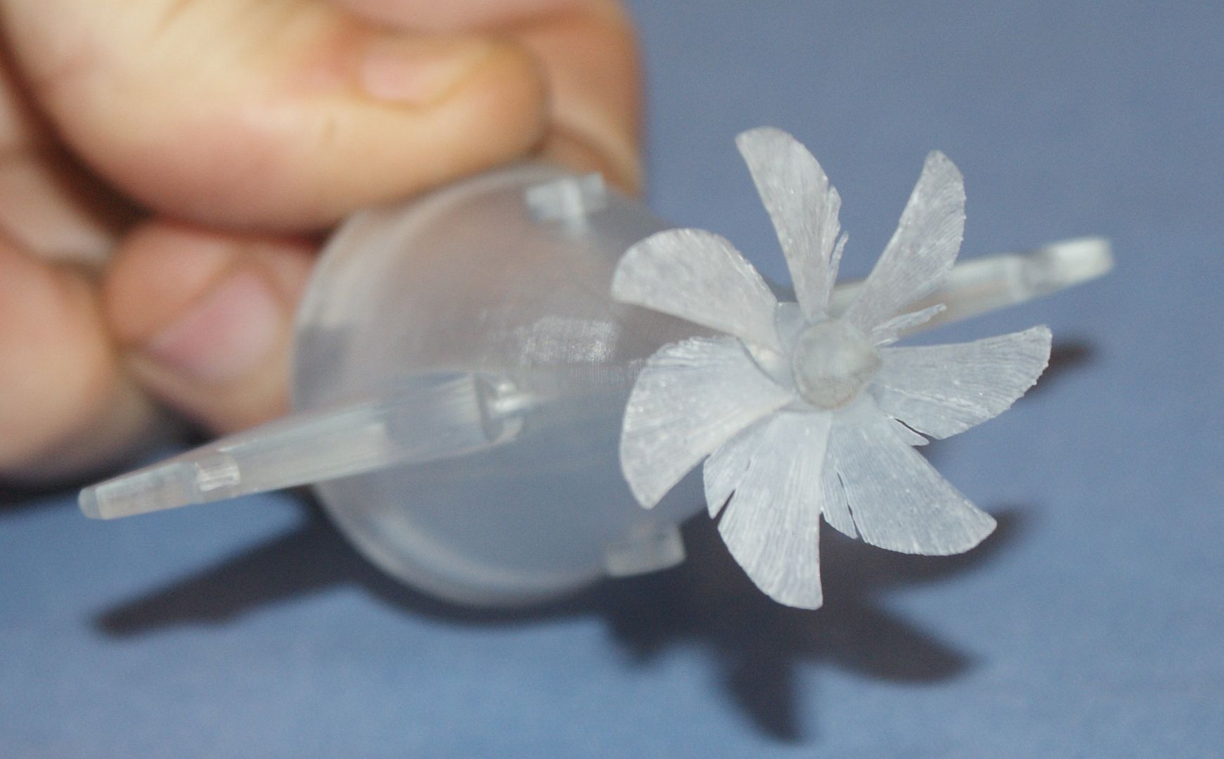
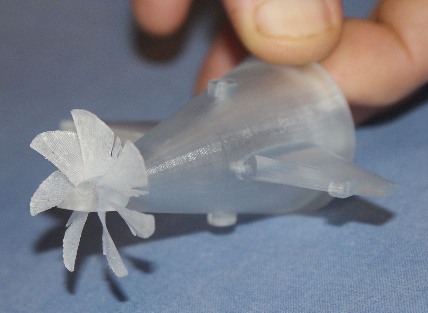
In the next two images, the feathering of the screw is evident. I hope the new parts aren’t feathered as badly, but if they are, I’m thinking that I could coat them with something prior to priming. The good news is that, although the screw is delicate, it isn’t as fragile as I thought it would be, so I think it will work fine as is. Whether or not it is stout enough for low temperature casting is another question.
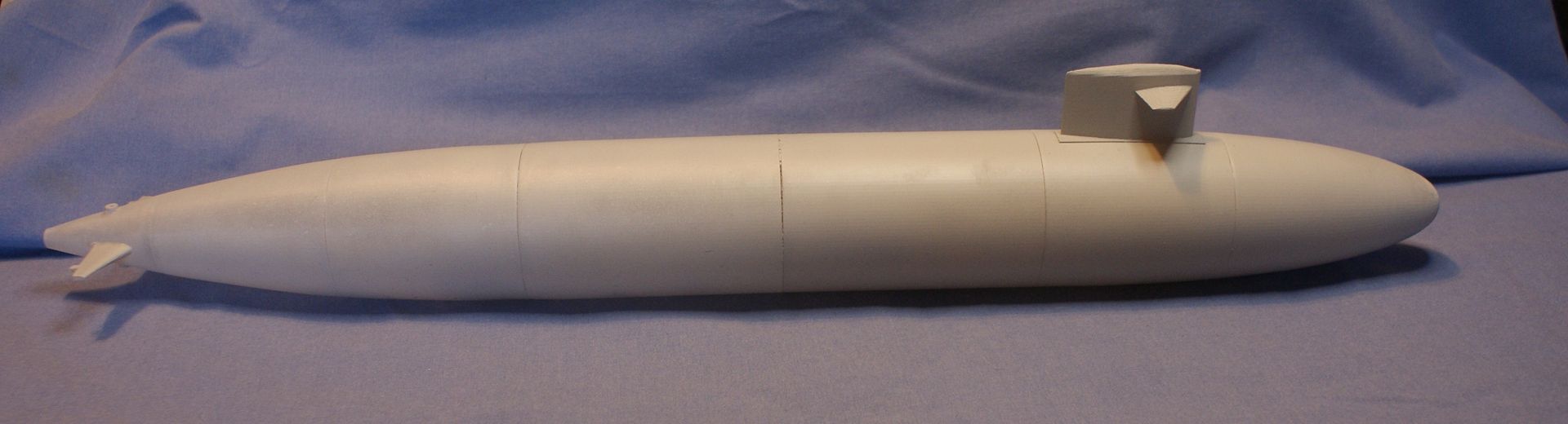
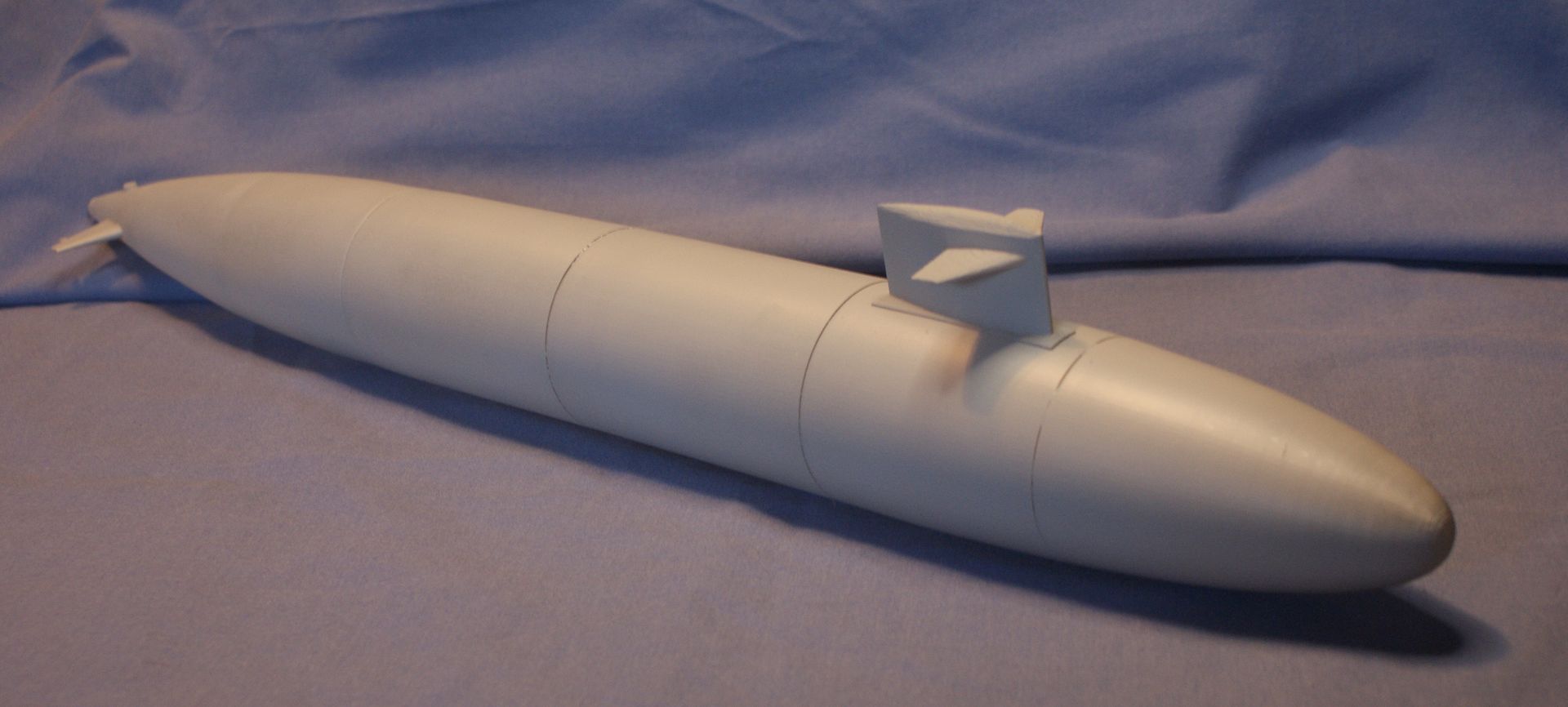
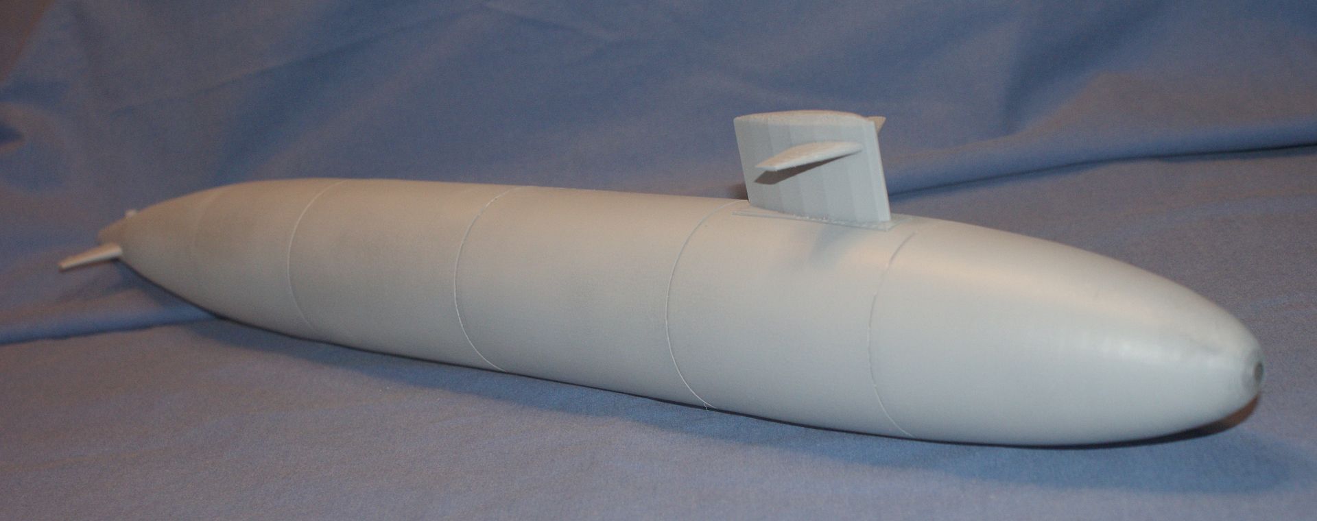
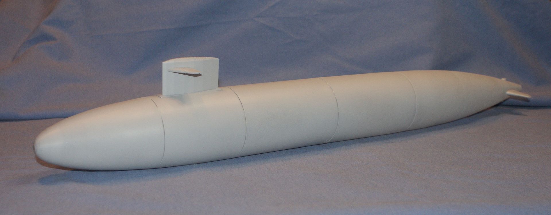
The last two photos show the sail assembled onto the hull. At this point I haven’t sanded the base of the sail. Doing so would allow it to sit more flush with the surface, but even as it is, a little sanding on the top would do the job.
If anyone has any advice on scribing, painting, or any other facet of the build, I would love to hear it.
I'm not a scribing expert by any means, I have done a bit though. It's definitely one of those skills you get better at with a bit of knowledge, and a LOT of practice.
Plastics vary greatly in their suitability for scribing. I find thermoset resins- e.g. Epoxy, polyester, polyurthane better than thermoplastics e.g. polycarbonate, ABS etc.
Scribing into primer or other paints isn't very satisfactory in my experience. I'm referring to conventional air-dry type paints in this instance. The exception is two-pack paints, which cure as a thermoset resin- often polyurethane based. However this is not nice stuff to be spraying about (contains isocyanates), so you need to wear preferably an air fed mask, or at the very least a charcoal based mask in a well ventilated area (e.g. outside). Generally you'll only get this sort of paint from places that sell to the car refinishing trade. Generally the minimum order is half or one litre (one or two pints) of paint. So you would need to buy more than you will use on a mini modal like this.
The only way to know for sure how your model will scribe is to try working on a scrap piece, or on an area of the boat that you won't see e.g. under where the sail will attach.
You want razor sharp tools, and templates for any shapes you will be describing. The best results are generally achieved with the use of custom templates made using photoetch and GRP.
A real expert on scribing is Dave Merriman, and he wrote quite a few articles in past issues of the SCR describing techniques on how to scribe detail in. Well worth checking those out.
A very small model such as yours is real baptism by fire. The best of luck!
I have heard of Dave Merriman, and seen some of his models. I will definitely look for those articles.
Even so, it sounds like a lot of work to me. Perhaps more than I'm up for at this point.
You were right earlier. It would make a cool light. Hmmmm.....
Good Morning Everybody and HAPPY ST PATRICK’S DAY!
I haven’t started building the first draft model yet, because I still haven’t decided how I’m going to do it. I am considering 3 options, building and painting it as is, adding details by scribing before painting, and making it into a light, as suggested by Sub culture. Scribing might be a bit more than I am willing to attempt at this time, and the lighting suggestion, which may have been offered in jest, is really a cool idea, and I am giving it some serious thought. I may put the parts of the hull together later today, but we’ll see.
I did take some pictures of the stern assembly put together as far as I could go, since I am still missing a rudder. The rudder didn’t fit as nicely as the dive planes and required a little filing of the post to get it to fit. Dam’n Murphy! Still this was quickly done and now the rudder rotates freely on the post.
The big news is that I discovered that the School of Aeronautical and Mechanical Engineering (AME) at OU has a 3D printer. I am an Alum of AME (although it was AMNE at the time, the N being for Nuclear), and am currently teaching a surveying/AutoCad course in the School of Civil Engineering and Environmental Science. I talked to the professor in charge, and although I am not teaching solid modeling, I have been showing my students who arrive early the Greenling model I’ve been making, and want to show them the capabilities of AutoCad in addition to the Civil applications I am teaching them. I told him that, as well as my primary objective, which is learning for myself what the capabilities, and limitations of 3D printing currently are, and was able to get some parts printed.
The parts I printed included the rudder, the screw and dunce cap (the professor actually wanted to print these to see how good his printer would print them), and the final sail design with the detailing I added, as described in previous posts. I also made the test piece shown in a post on December 18, 2012.
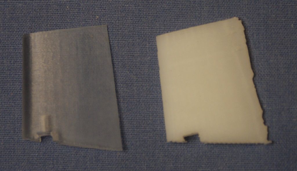
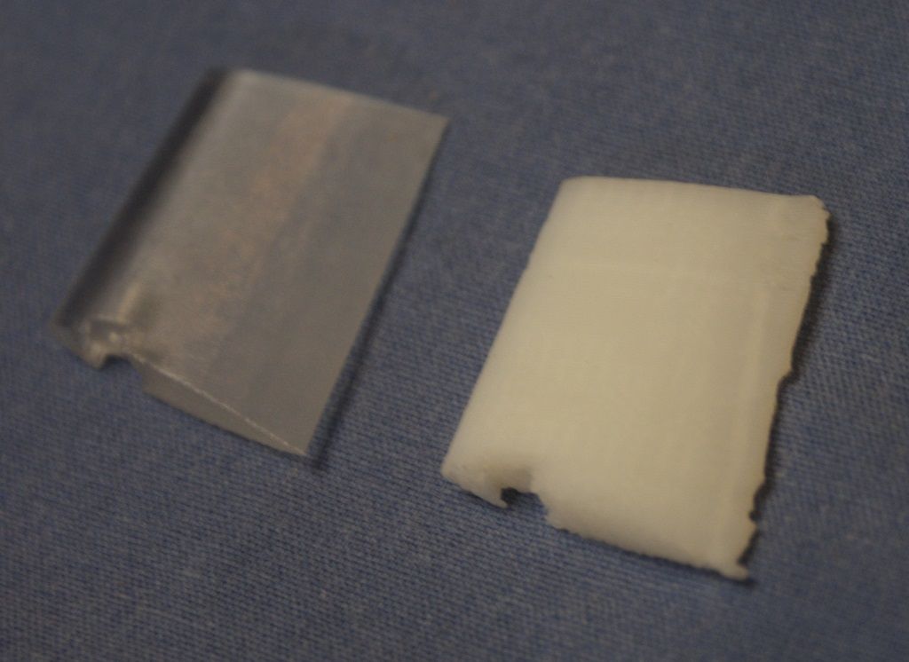
The first two photos show the rudders printed with the SLA (left) and OU’s printer (right). As you can see the detailing, especially the edges, is much cleaner on the part printed on the SLA than the one printed on OU’s printer.
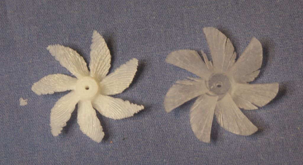
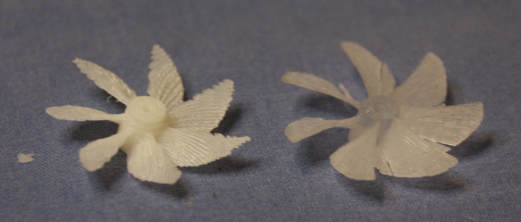
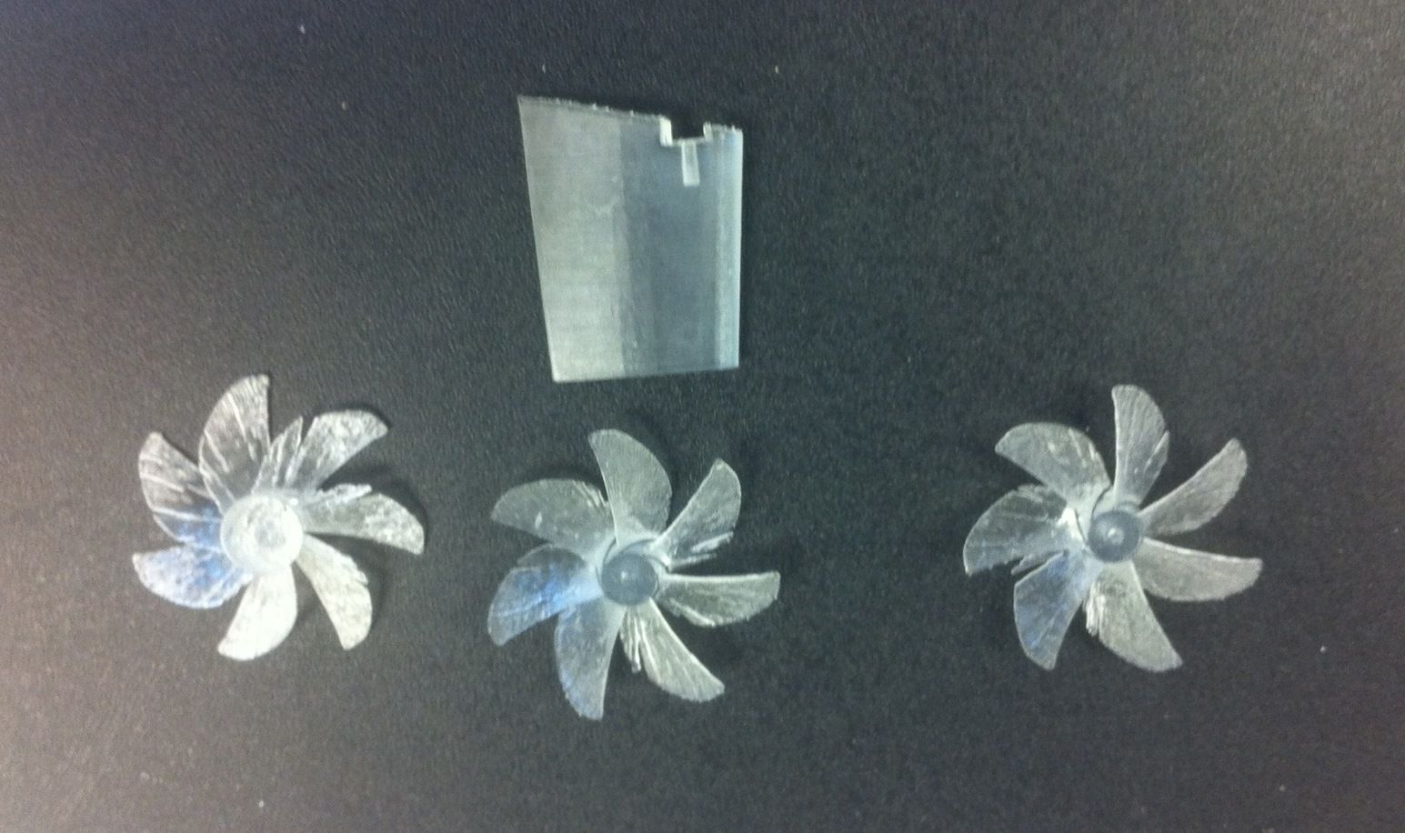
The next two photos show the screws made by OU’s printer (left) and by the SLA (right). Again you can see that the SLA part has cleaner edges. Also, the part made on OU’s printer is much more fragile and you can even see a piece that broke of it during simple handling. The dunce cap got lost in the cleanup process, at least temporarily, so it is not shown.
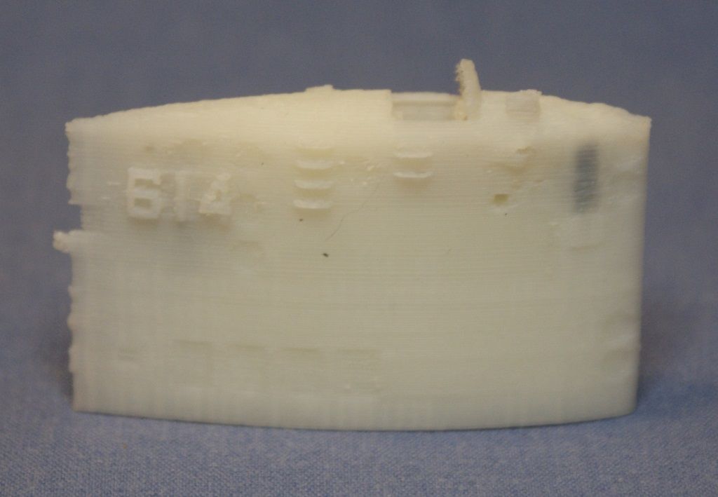
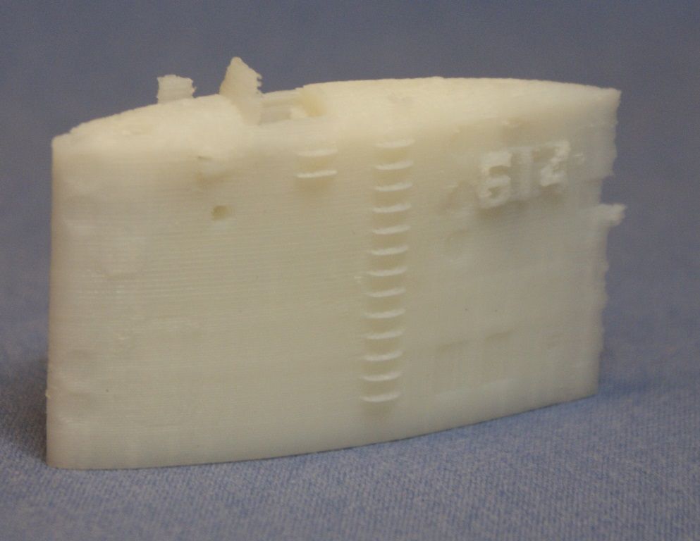
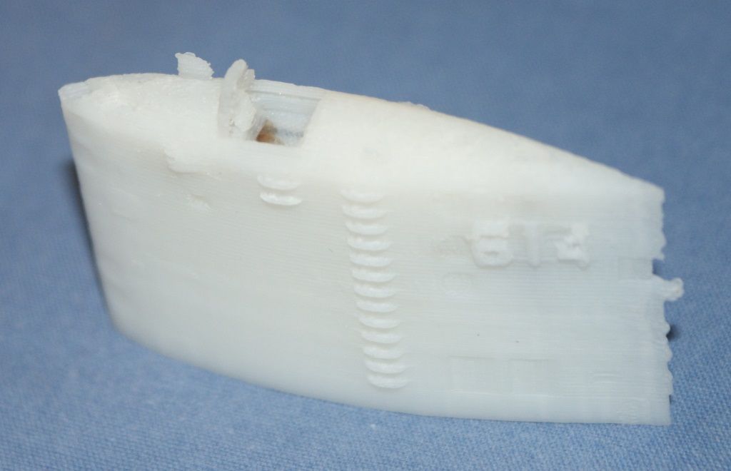
The next three photos are of the modified, detailed sail. These photos are really encouraging, because even though it was printed on the OU printer, much of the detail came out pretty good. The hull numbers, ladder rungs, and windshield came out pretty good, and you can even see the portable control panel in (on?) the bridge. However, even though the indentions for various plates are present, the edges aren’t well defined, and the pig stick and the fairing on the sail didn’t come out very well. The holes for the various periscopes and masts are of varying quality, some would be useable, some not so much.
Overall, I would say that the results are encouraging. The OU printer can almost generate the desired quality, and as you have seen, the SLA quality is better, so I am still hopeful that I can get the detailed parts I want from the SLA. The parts I am most concerned about are the periscopes and masts, because they are so small. However, nothing has a smaller diameter than the shaft on the dunce cap and it came out great, so again I am hopeful.
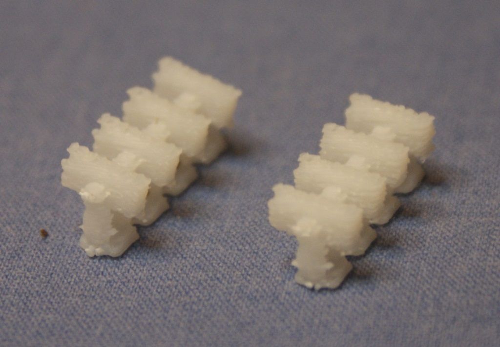
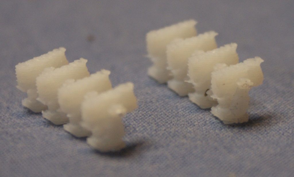
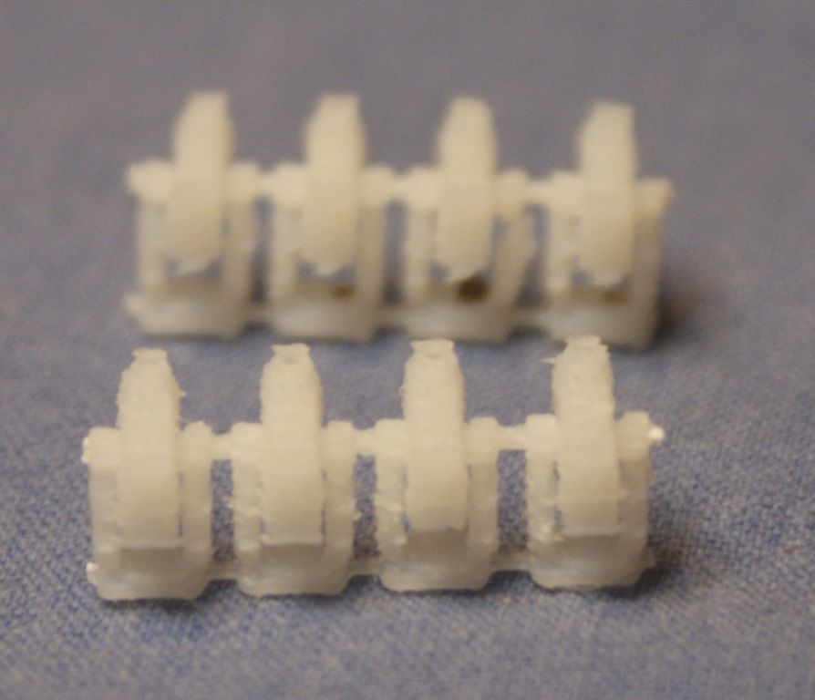
Although slightly off topic, as it has nothing to do with submarines, much less Greenling, I mentioned that I also printed a test piece. The test piece had eight 1/350 scale RAM Launchers tucked inside of it. They look pretty cool with the naked eye, although they don’t quite pass the scrutiny of a telephoto lens. Still, I thought you might like to see them.
Again, I can’t wait to see how these come out on the SLA.
I think, based on these results, that I should have my buddy print just 4 parts before printing the entire model, the test piece, the sail, the snorkel injector, and Hull Section 1. Then go from there.
My buddy sent this pic to me in a text this morning. The forgotten rudder has been made along with three extra screws. They all have feathering to some degree, but having 4 of them will give me a couple of tries at fixing them.
My buddy is going to ship them to me. I will let you know when they arrive.
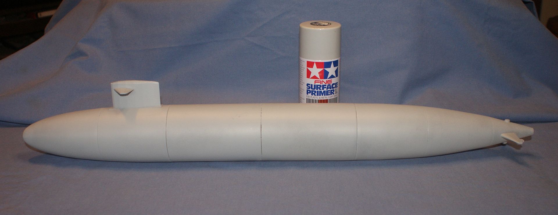
I still haven’t received the rudder and extra screws, but I did put the hull together. I also decided not to build it as a light, so I went ahead and primed it. I only put about a coat and a half on it because even though it seems like there is plenty of primer in the can, the pressure dropped. I tried cleaning the nozzle with thinner, but it helped only marginally, so it looks like I will be making a trip to my local hobby shop for more.
Anyway, you can see in the pictures below that I have some seams to fill. I was thinking about using “White Putty†from Squadron Products, but am open to suggestions if anybody has any.
I haven’t decided for sure yet if I am game to take on scribing the details, as I have only scribed one thing before, an extra catapult on USS Bennington, and it came out OK, but not great. I’m kind of leaning toward building it as is, perhaps scratch building the fairings, mushroom anchor and maybe some of the periscopes/masts, especially since I think my buddy will eventually make the detailed version for me, although it might not be any time soon. I know that he felt real bad about not sending the latest files to the guy who actually made them, but I don’t want to push too much because he was super generous to offer to make anything.


Comment