
I started this thread in the Static Modeler section but since this is a build that will take some time I'm posting the rest my build here. If you haven't seen the first few posts in Static Modeler section, you might want to check those out first to see what my plan is.
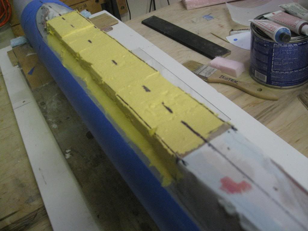
I mentioned previously that I wanted to layout the bottom details so I knew where to locate the clear plastic rods for supporting the model. Laying out the openings in pencil over the primed hull and confirming their accuracy is necessary to avoid mistakes before cutting into the hull. The picture below shows the main seawater suctions and discharges port and starboard as well as number 4, 5 and 6 main ballast tank inlets port and starboard. The circle on the far right is where the after support will be located just forward of MBT #4.
http://i345.photobucket.com/albums/p392 ... G_4962.jpg
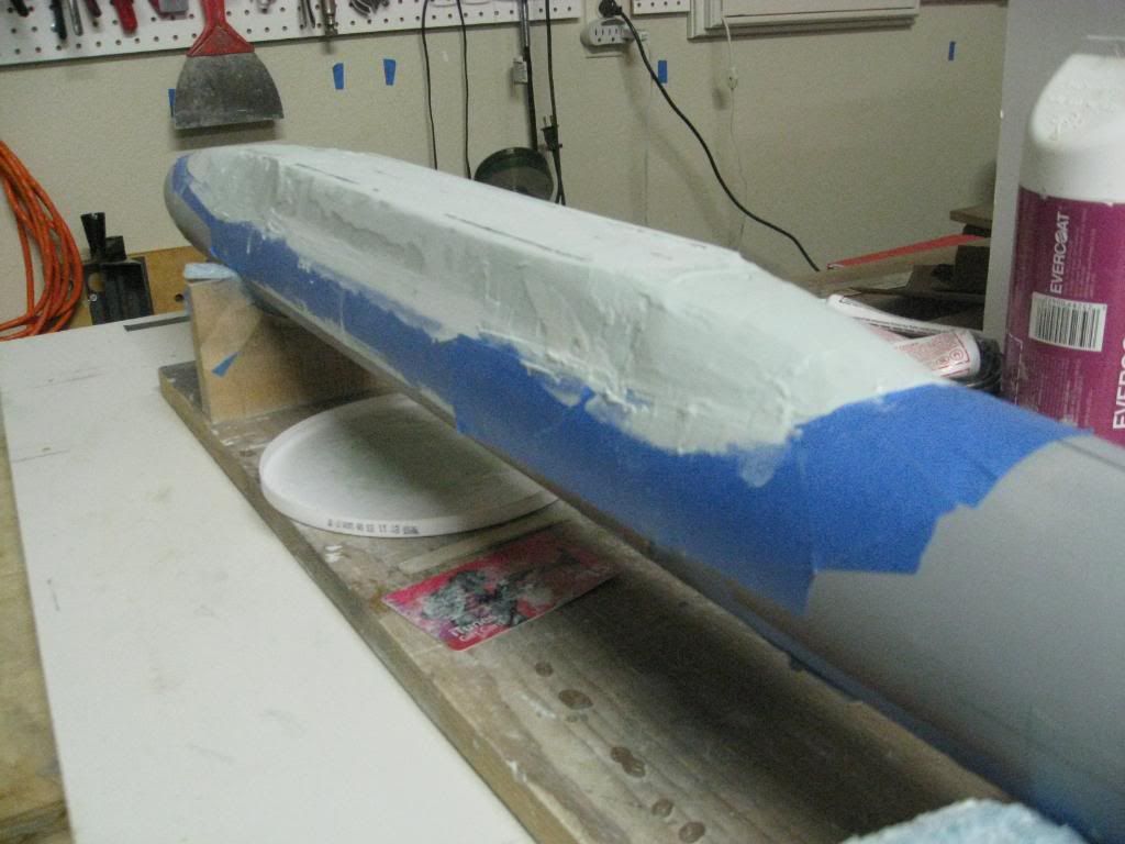
The forward MBT inlets as well as the anchor and other details are shown in the next picture. The forward support rod will be located just aft MBT #3 inlets. It’s important to remember the docking plan shows the hull as if you were inside the hull looking down. But when laying out the details the hull is upside down so port and starboard orientation can be confusing. Note my crossed out marking forward of the anchor.
http://i345.photobucket.com/albums/p392 ... G_4963.jpg
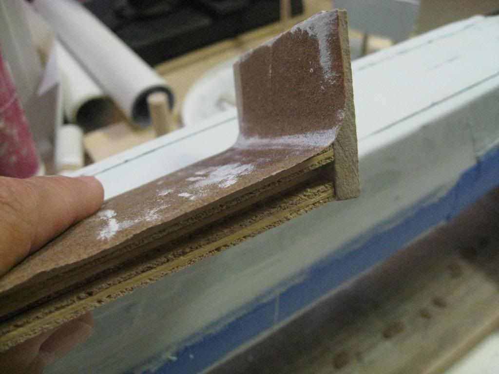
Blue painters tape can be used for several different tasks. Here the tape is used to mark locations that were cut out for MBT inlet grates that will be installed later. A hole was drilled in the hull between the taped boundaries and the opening enlarged by filing up to the edge of the tape. The tape also protects the hull for those times when I might have otherwise scratched the hull by accident.
http://i345.photobucket.com/albums/p392 ... G_4981.jpg
Finally, here is where the hole for the forward support rod was drilled just aft MBT #3.
http://i345.photobucket.com/albums/p392 ... G_4977.jpg
To be continued.
"Will" Rogers
SSBN659
I mentioned previously that I wanted to layout the bottom details so I knew where to locate the clear plastic rods for supporting the model. Laying out the openings in pencil over the primed hull and confirming their accuracy is necessary to avoid mistakes before cutting into the hull. The picture below shows the main seawater suctions and discharges port and starboard as well as number 4, 5 and 6 main ballast tank inlets port and starboard. The circle on the far right is where the after support will be located just forward of MBT #4.
http://i345.photobucket.com/albums/p392 ... G_4962.jpg
The forward MBT inlets as well as the anchor and other details are shown in the next picture. The forward support rod will be located just aft MBT #3 inlets. It’s important to remember the docking plan shows the hull as if you were inside the hull looking down. But when laying out the details the hull is upside down so port and starboard orientation can be confusing. Note my crossed out marking forward of the anchor.
http://i345.photobucket.com/albums/p392 ... G_4963.jpg
Blue painters tape can be used for several different tasks. Here the tape is used to mark locations that were cut out for MBT inlet grates that will be installed later. A hole was drilled in the hull between the taped boundaries and the opening enlarged by filing up to the edge of the tape. The tape also protects the hull for those times when I might have otherwise scratched the hull by accident.
http://i345.photobucket.com/albums/p392 ... G_4981.jpg
Finally, here is where the hole for the forward support rod was drilled just aft MBT #3.
http://i345.photobucket.com/albums/p392 ... G_4977.jpg
To be continued.
"Will" Rogers
SSBN659


Comment