MODELING THE USS WILL ROGERS

Collapse
X
 
  • Time
  • Show
Clear All
new posts
  • bill rogers
    Junior Member
    • Sep 2003
    • 90

    #16
    Re: MODELING THE USS WILL ROGERS

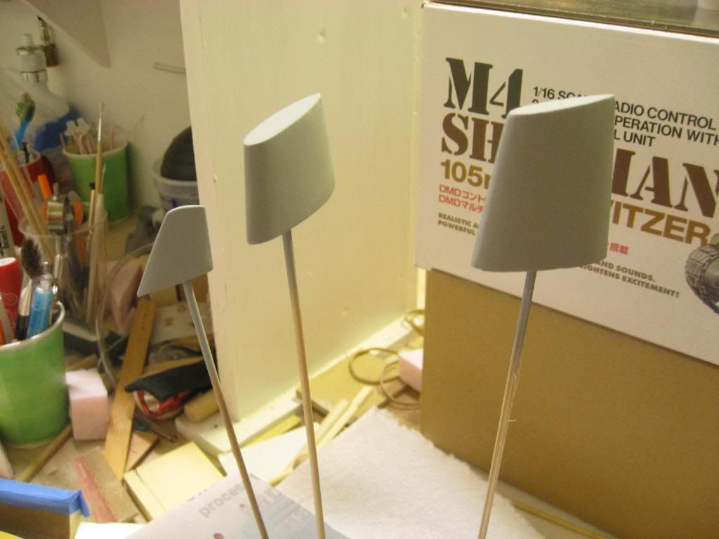
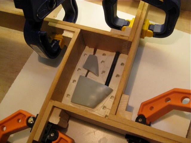
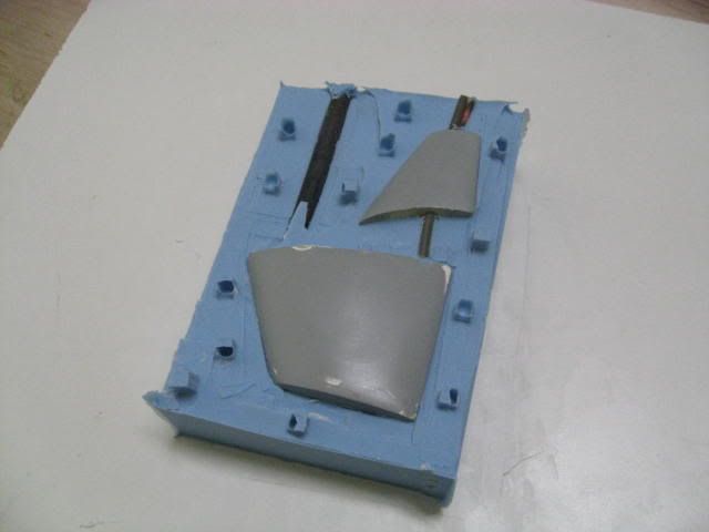
    During the construction of my model I took a break to assemble a Tamiya model of the M-4 Sherman tank for a neighbor. It was a welcome break from sanding and shaping but I have to say that building from scratch is a lot more satisfying than assembling a model from a kit. So now back to the USS Will Rogers.

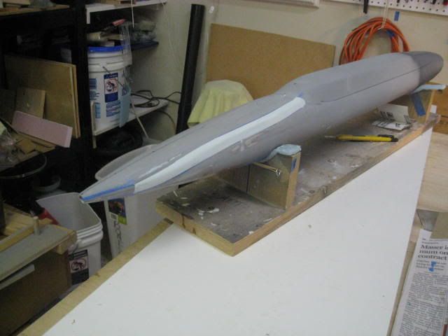
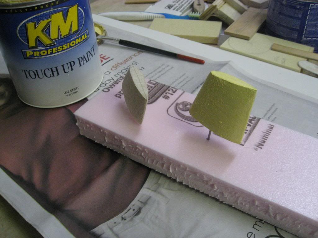
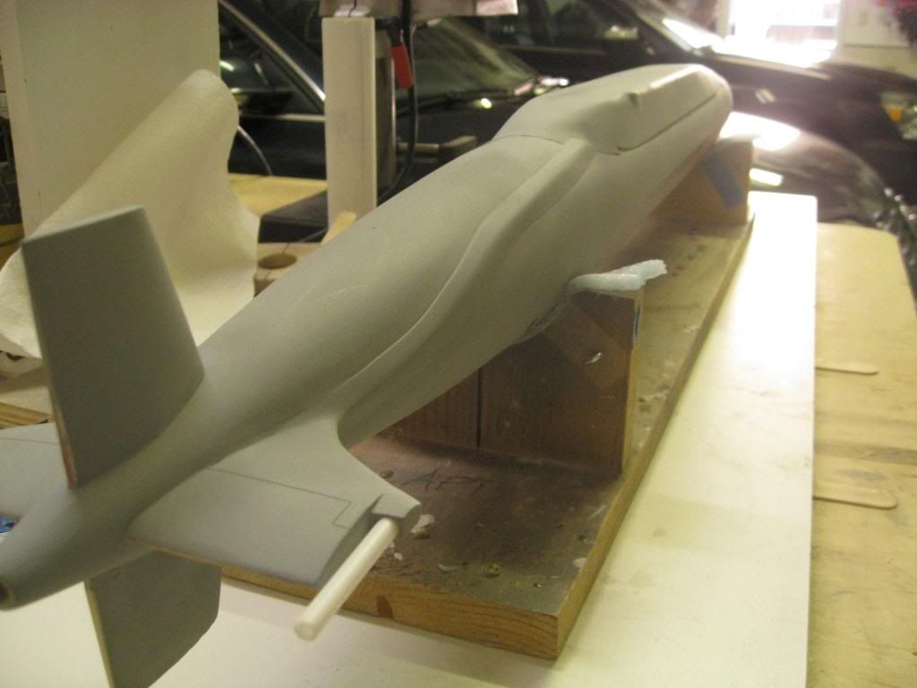
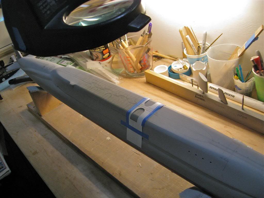
    Here’s the hull and superstructure almost complete. There is some touch up work needed but that will come later. The strange looking pieces on the bench next to the hull are not for the submarine. They were for the M-4 Sherman.


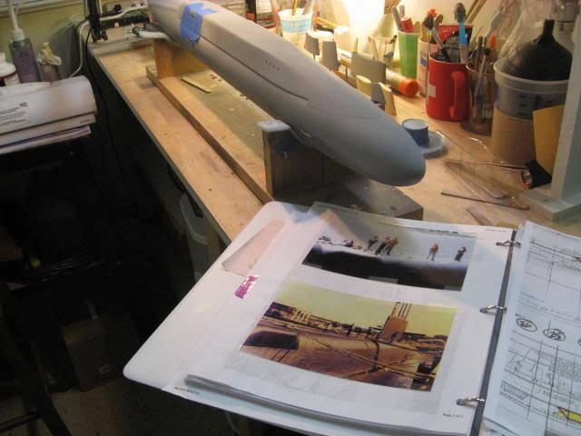
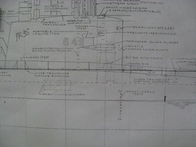
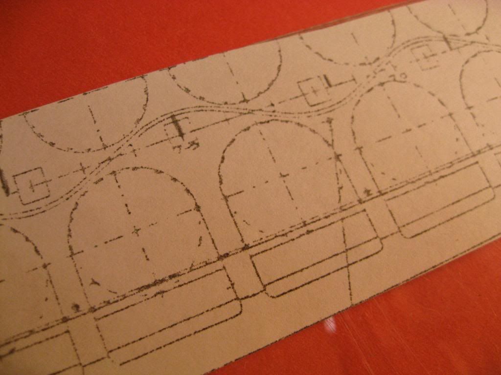
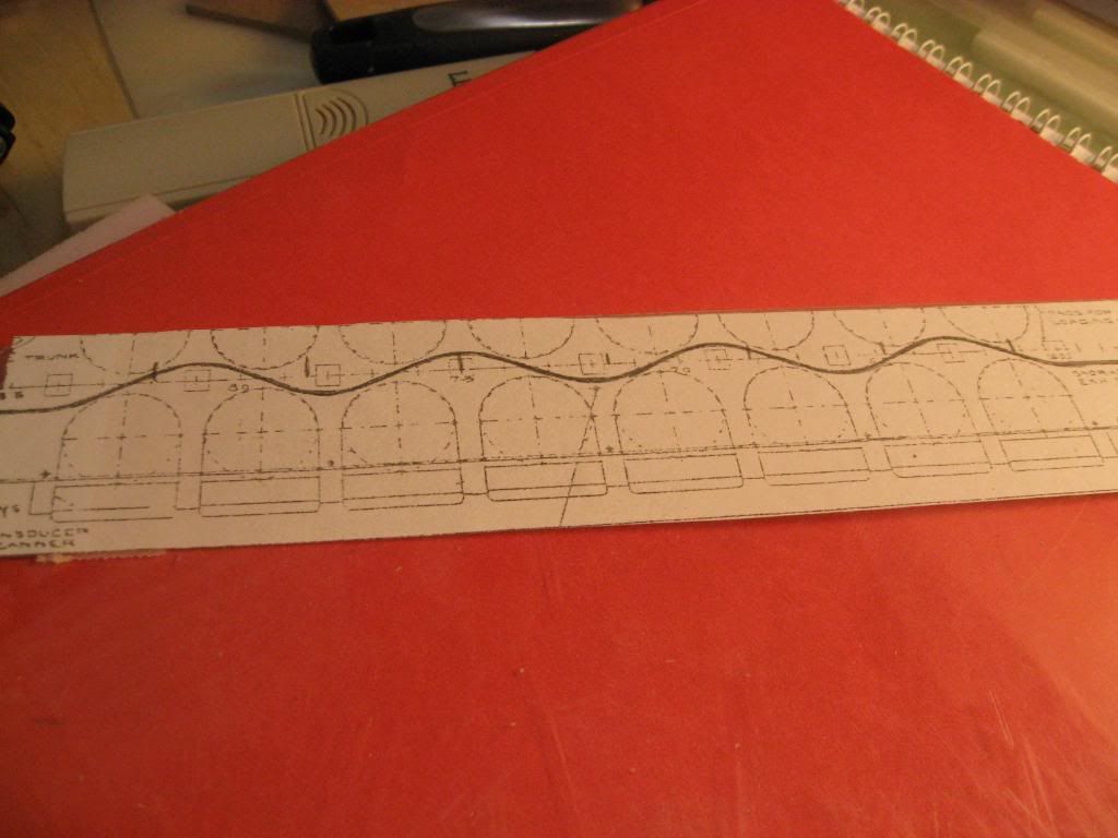
    My research of the Forty-One For Freedom turned up several pictures that are invaluable in building my model. Since the basic shape of the Lafayette and Benjamin Franklin Class boats is the same in most cases it was easy to get photos of details I wanted to represent. In many ways the photos are even more help than the set of drawings I found because they depict shape, color, contrast, etc.

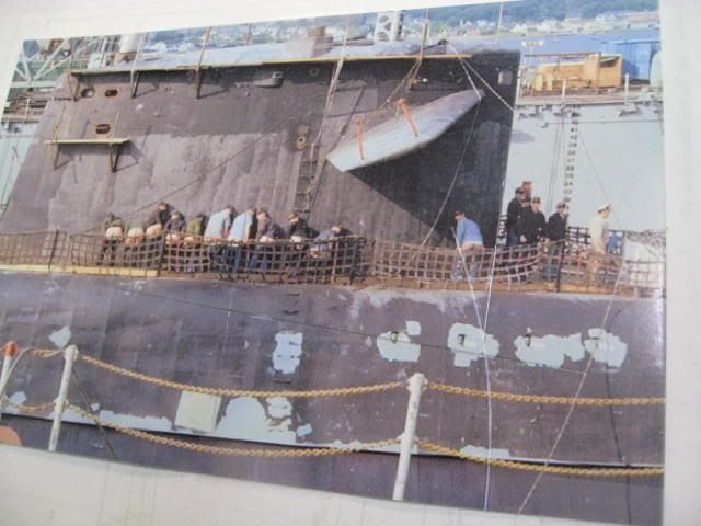
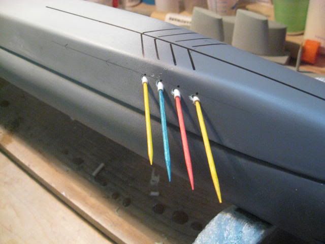
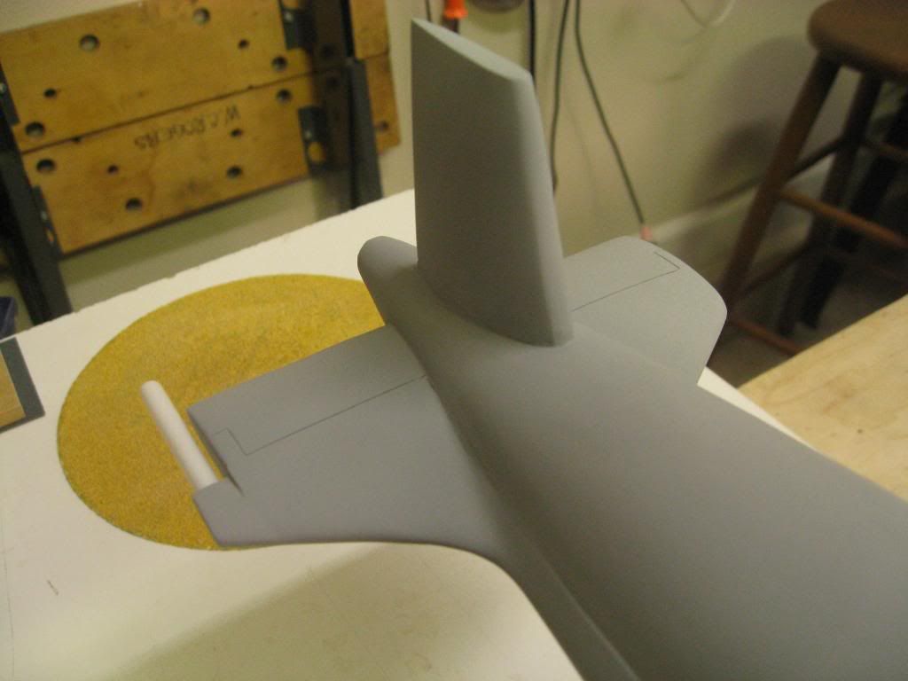
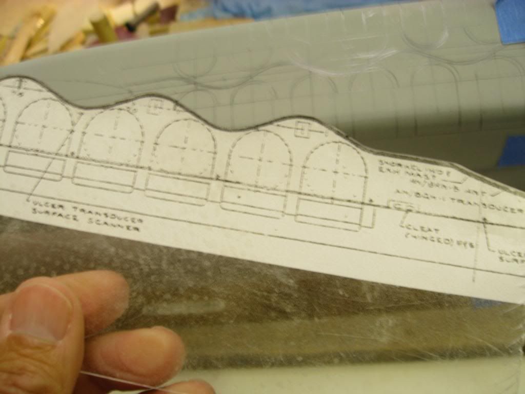
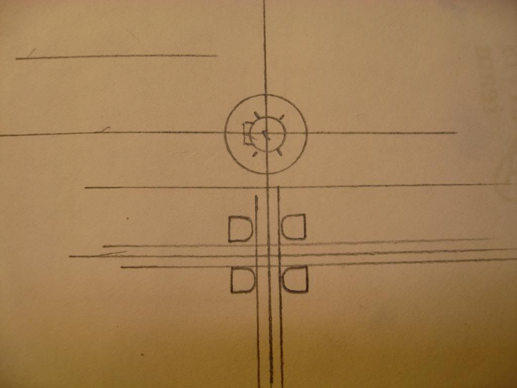
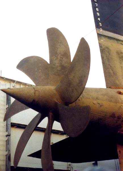
    My next step was to tackle the BQR-15 Towed Array as depicted in the following two photos. Interestingly, I found pictures of SSBN 619 with a towed array and one of 629 without one. Go figure that one out. Anyway, I was able to confirm that Will Rogers had one. Note the detail these photos provide.


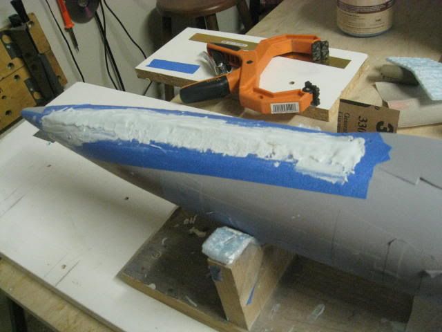
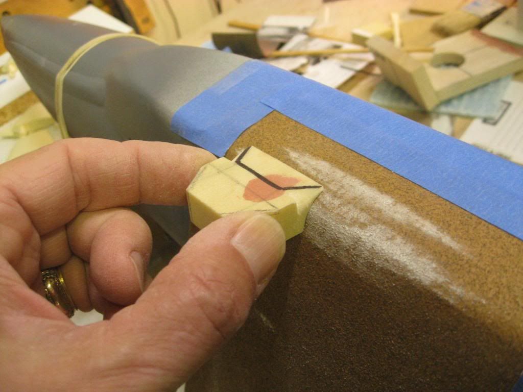
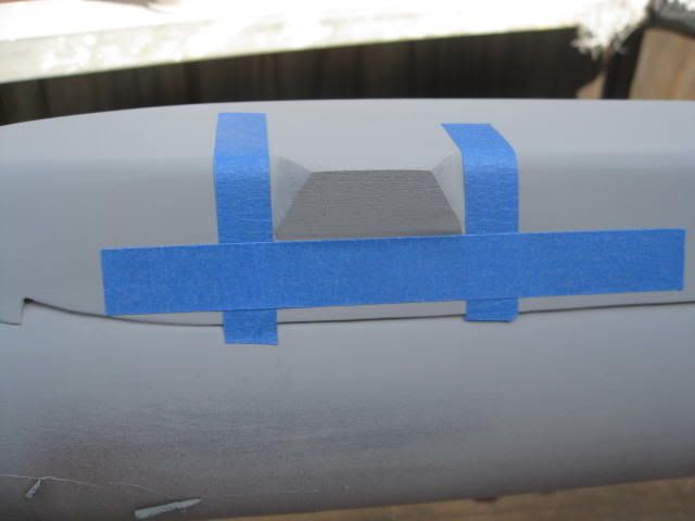
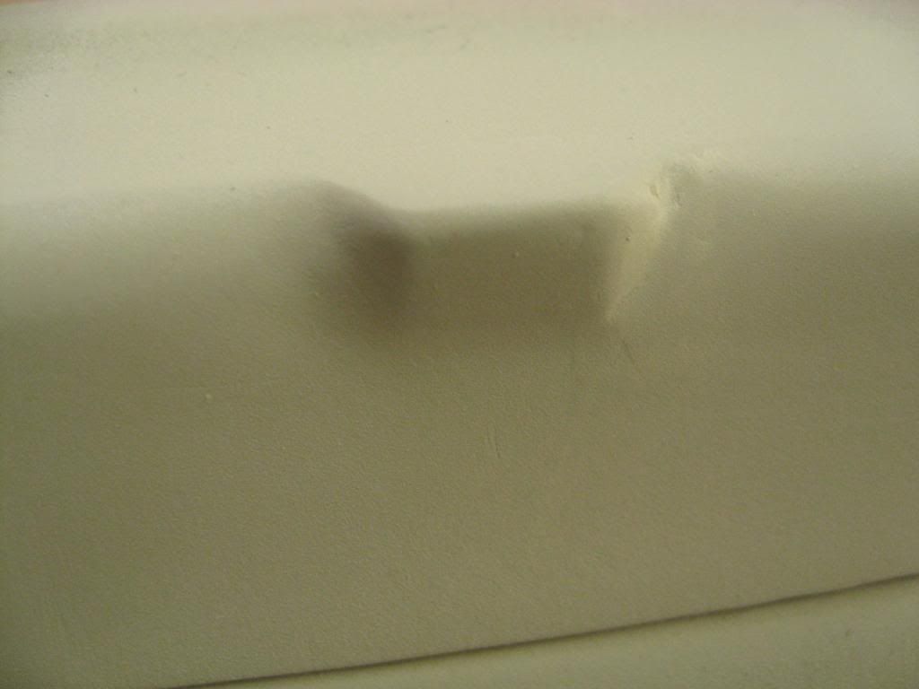
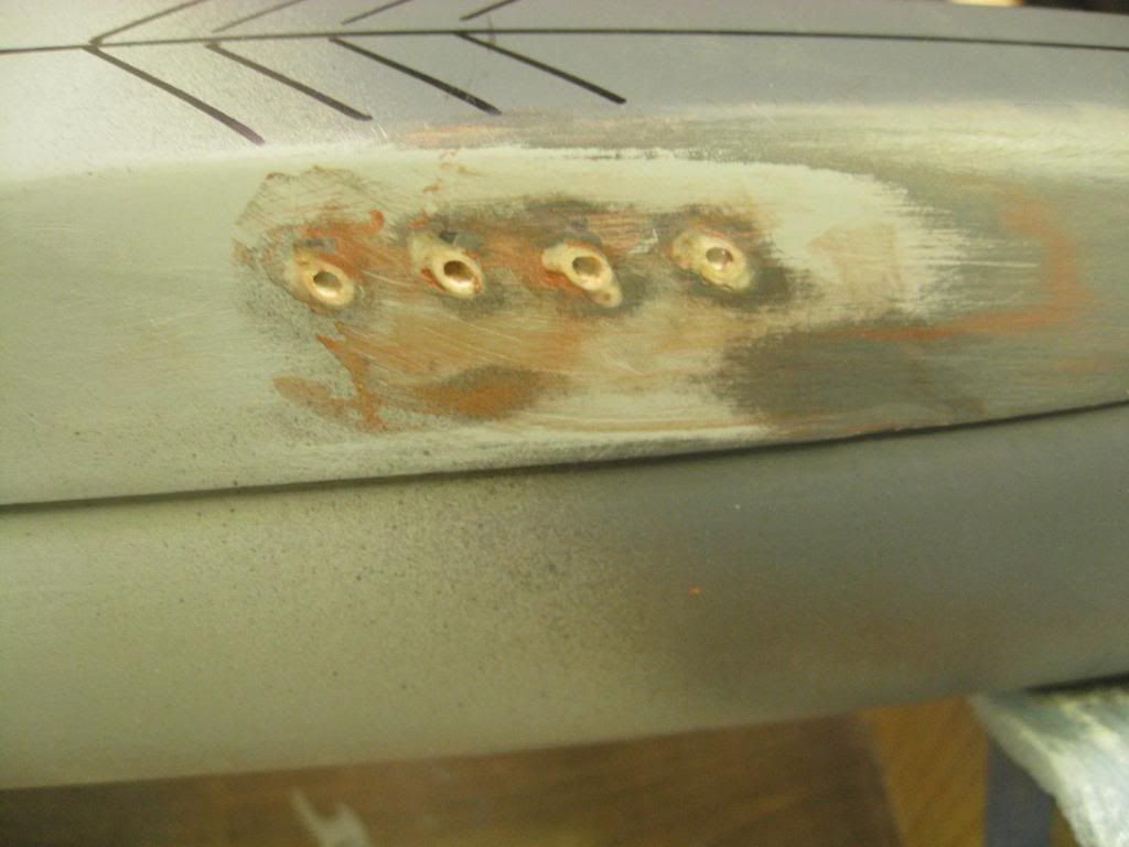
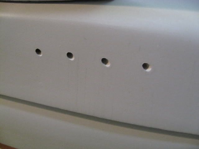
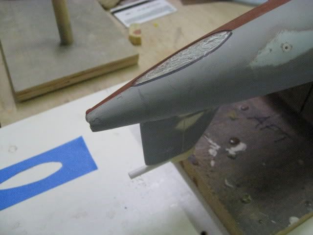
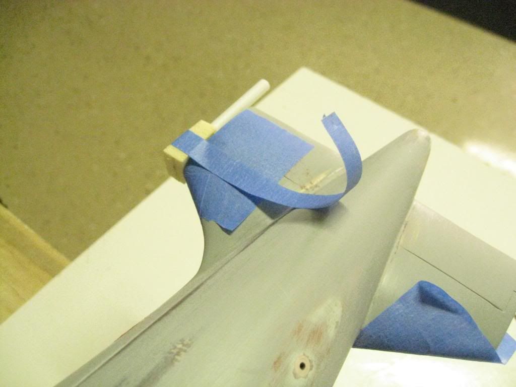
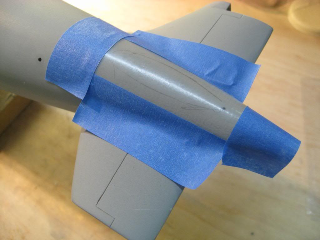
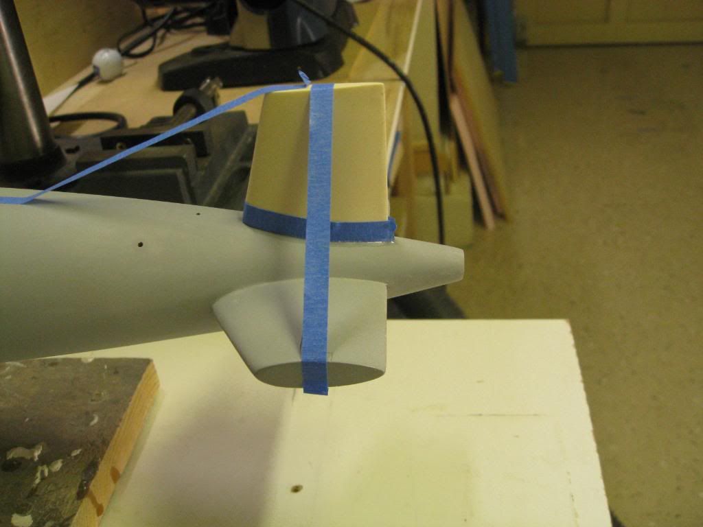
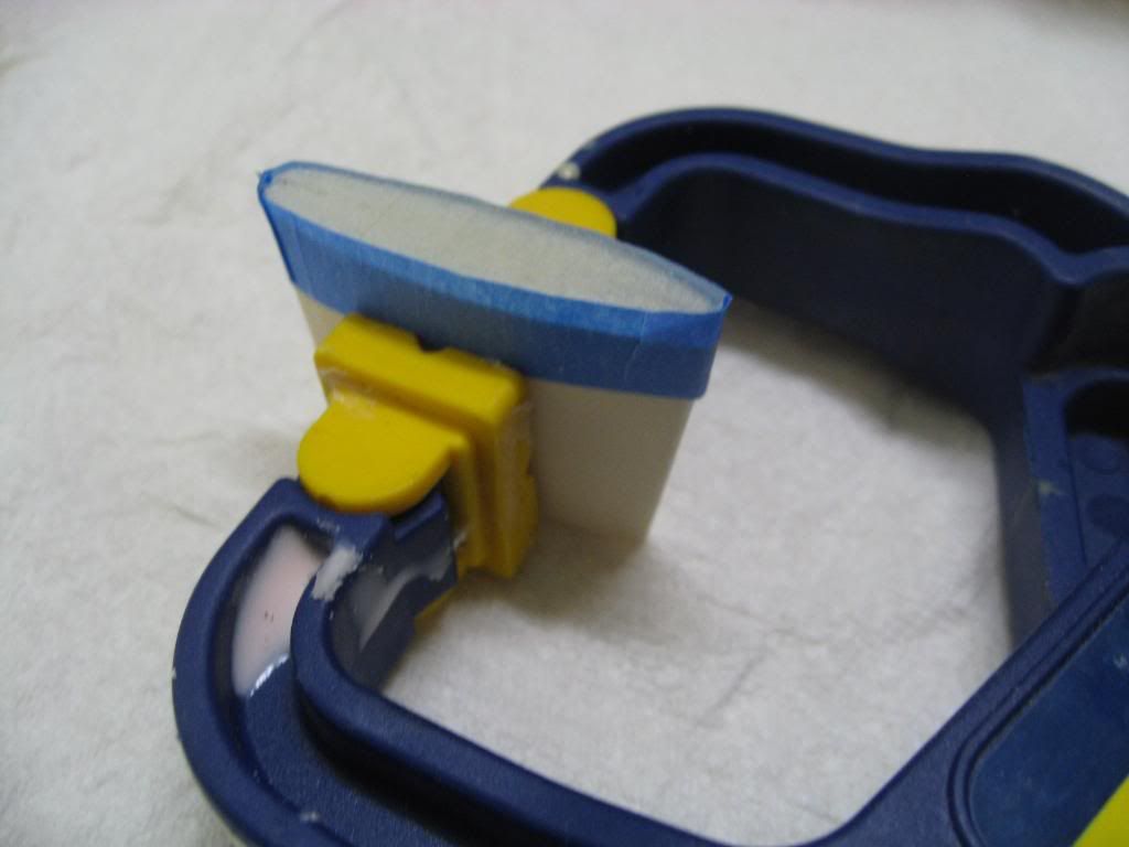
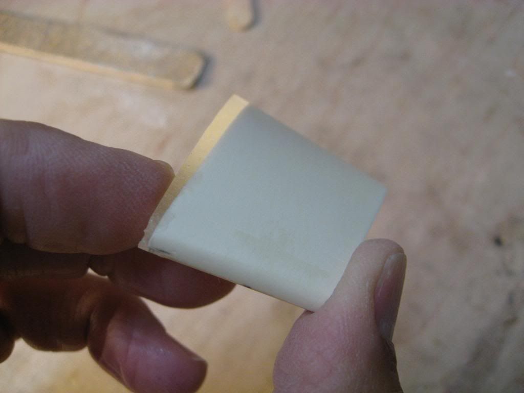
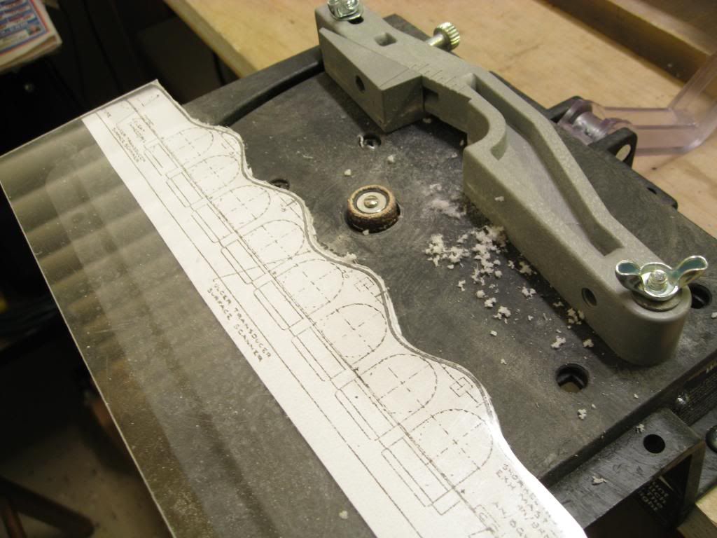
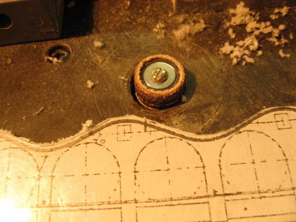
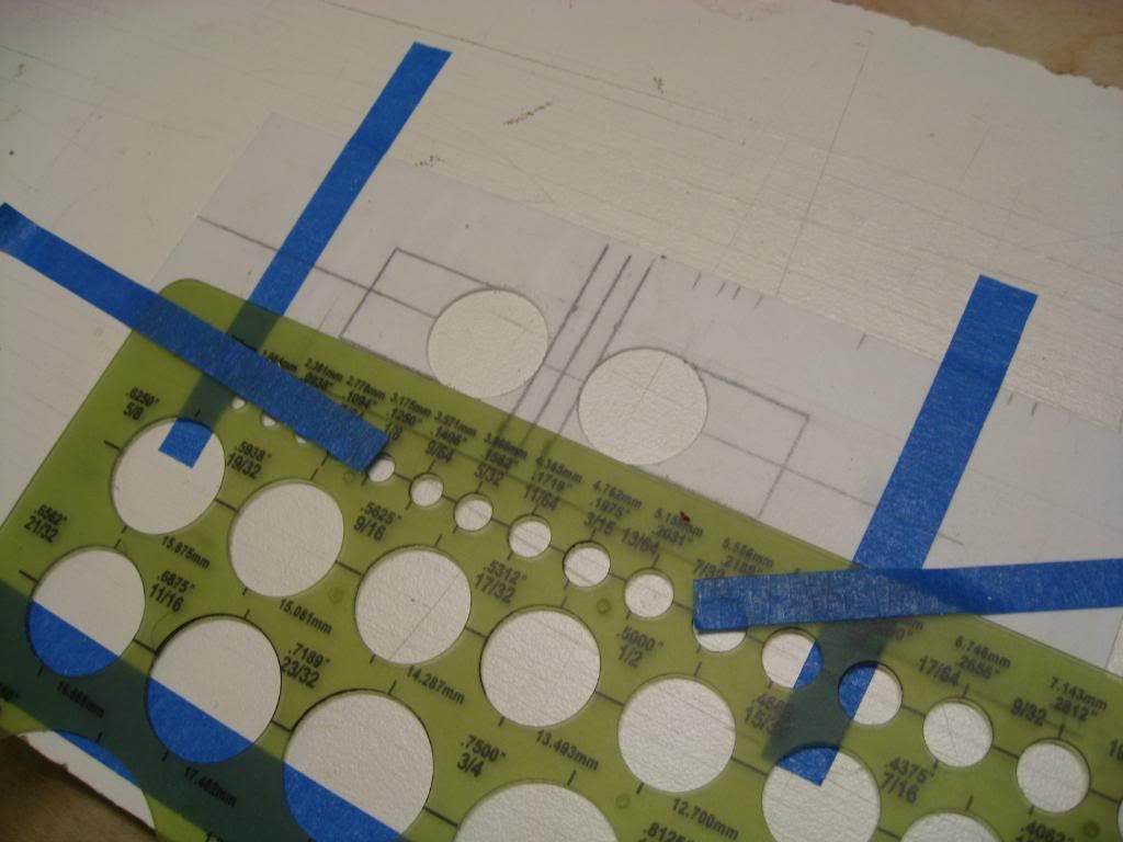
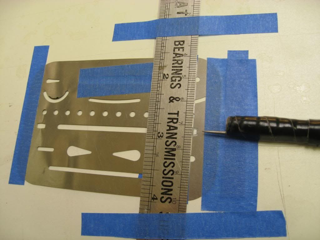
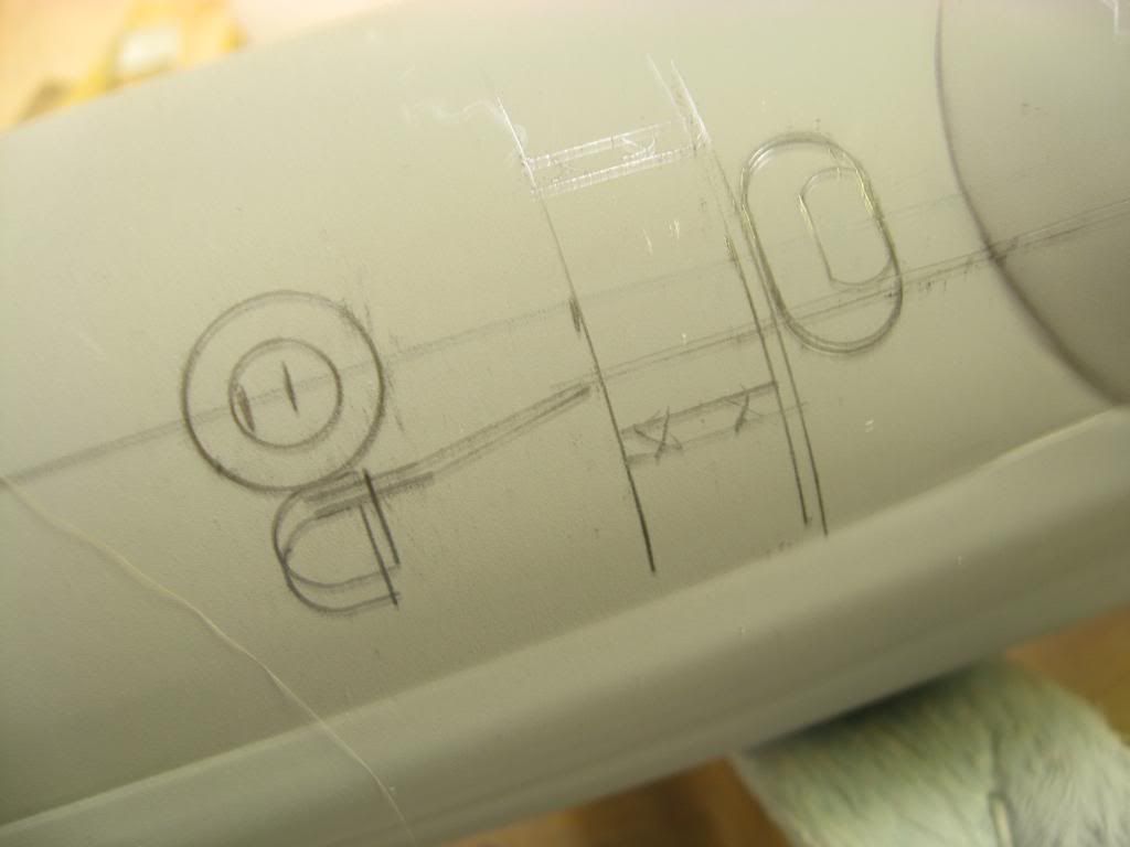
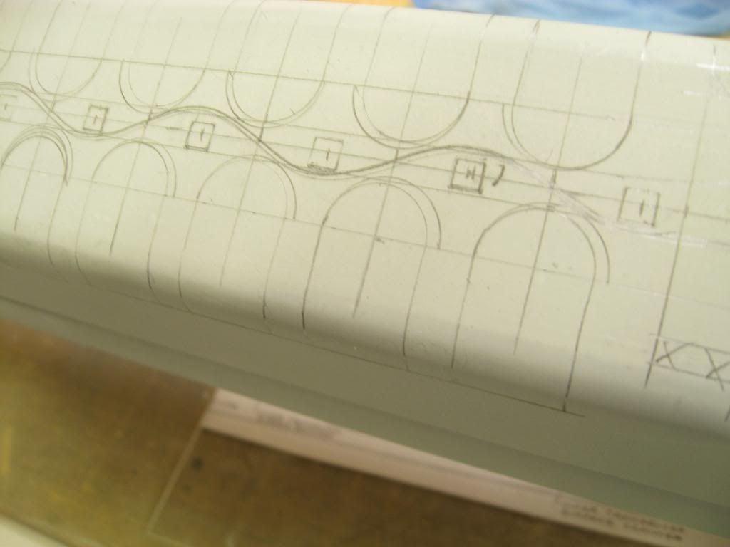
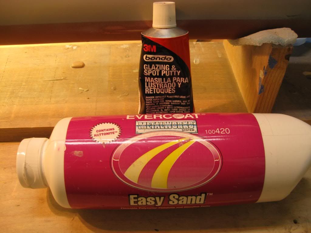
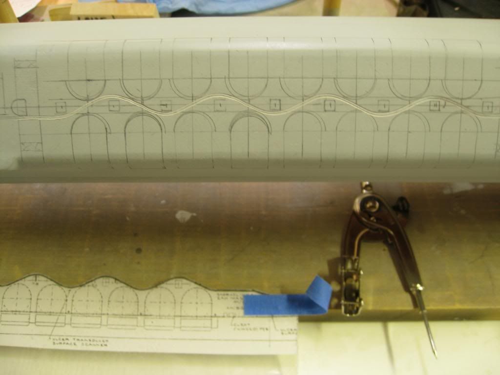
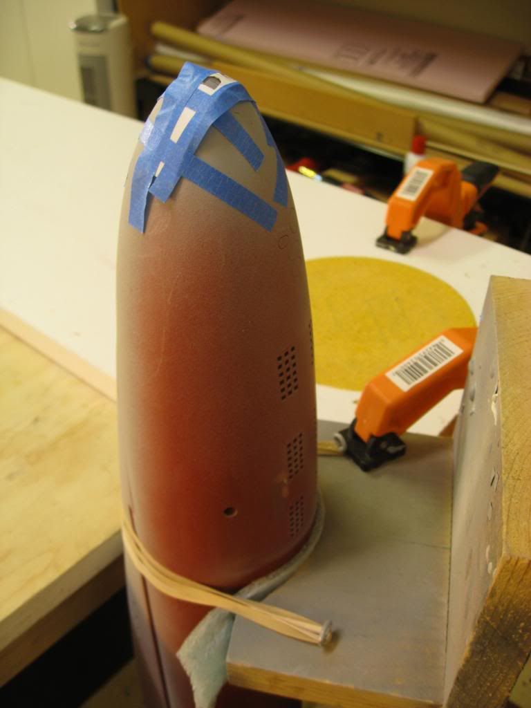
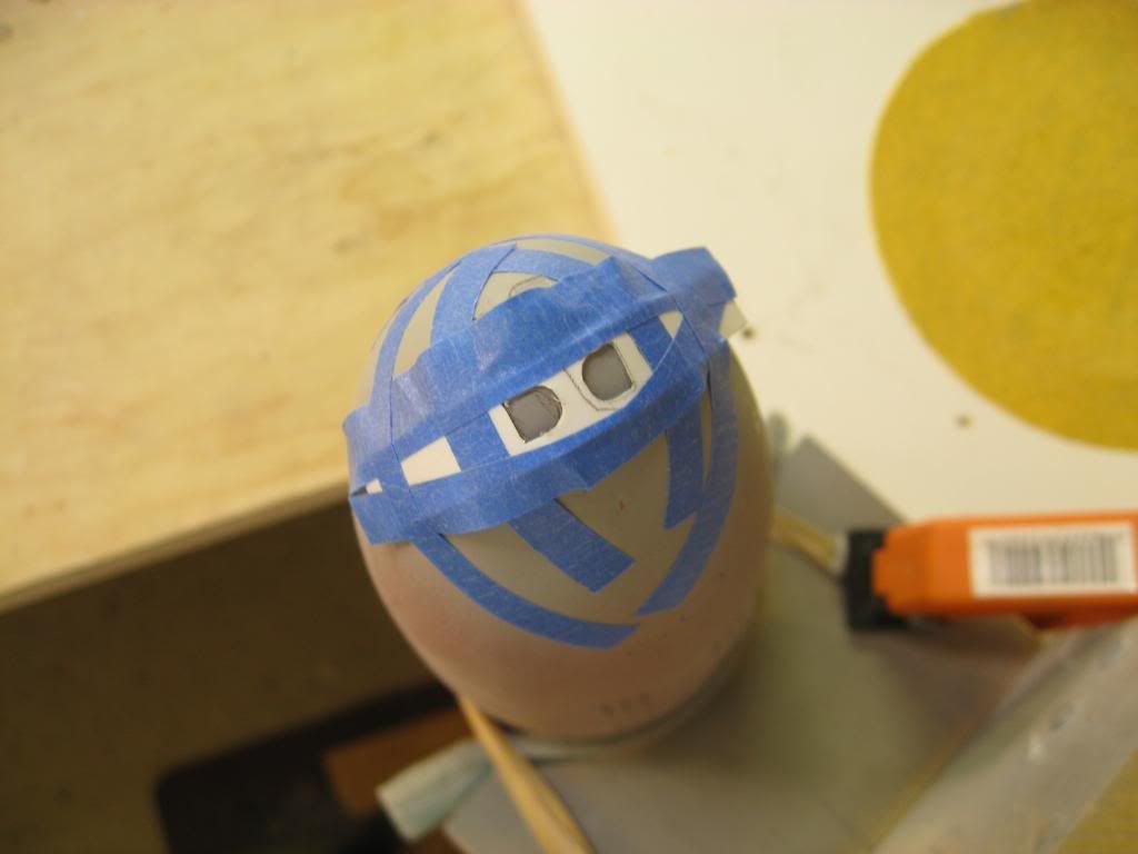
    From the drawings and photos I drew an outline of the array fairing on the hull and then taped it. Using the polyester filler I built up a rough shape. I tried using a screed made from a used iTunes card with a semi-circular notch cut in the side. This didn’t work out very well so I finally “troweled” on the filler using the flat edge of the card.


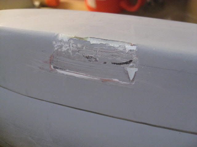
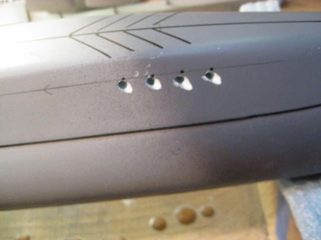
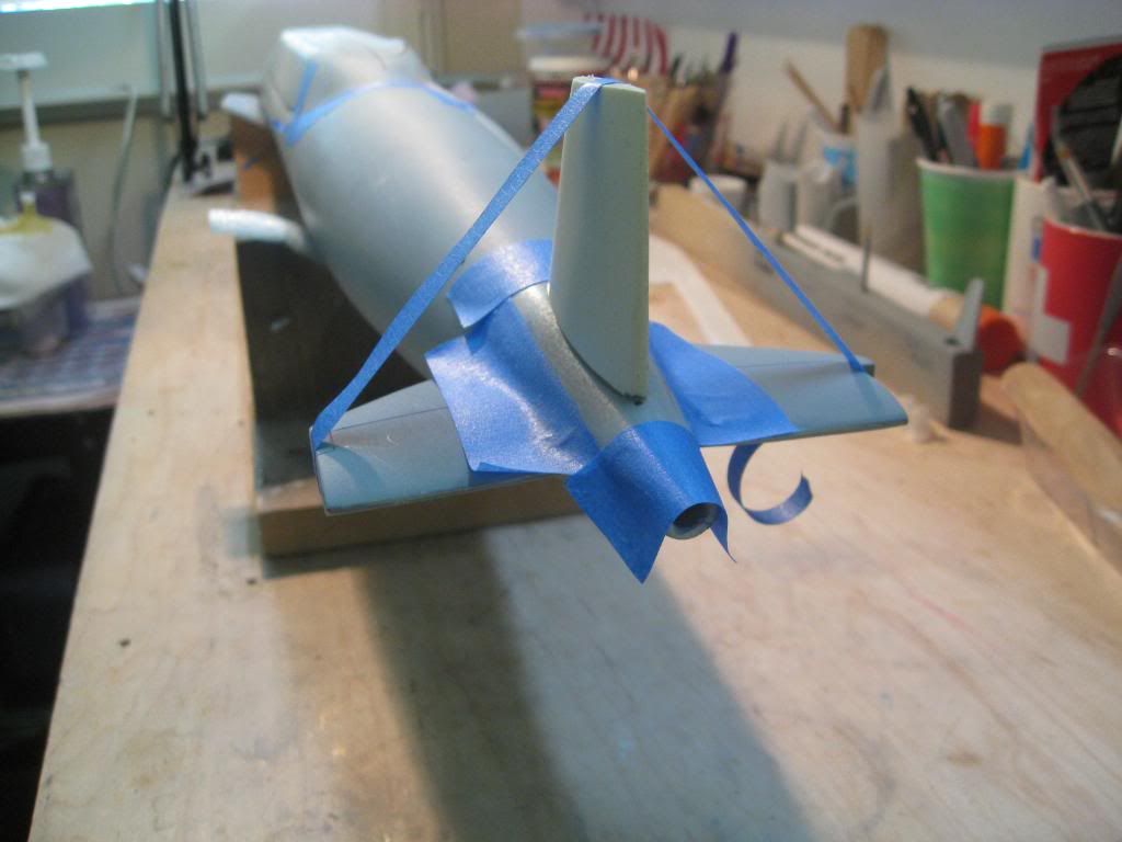
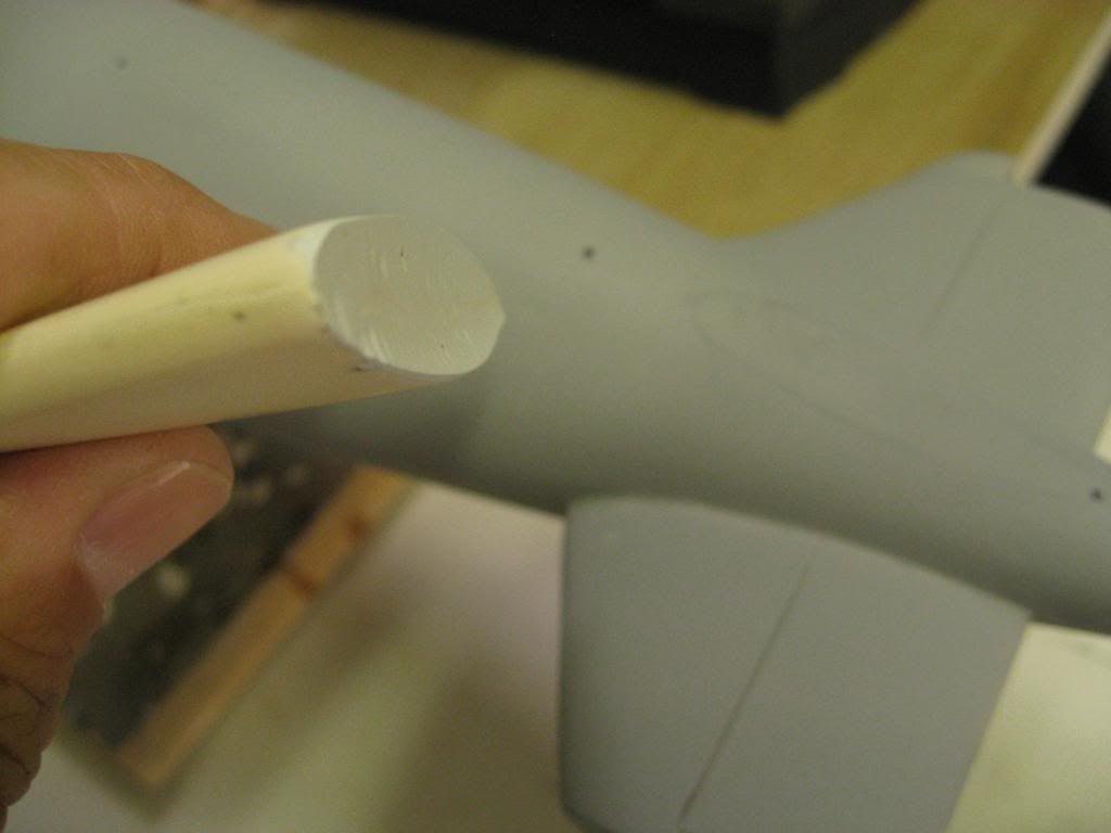
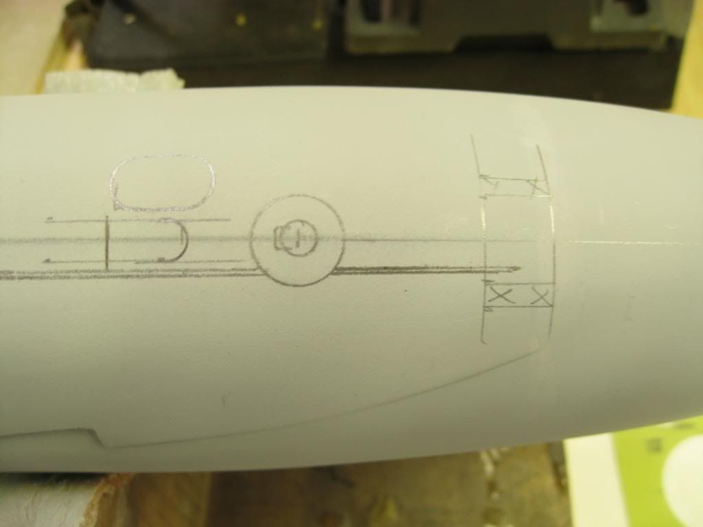
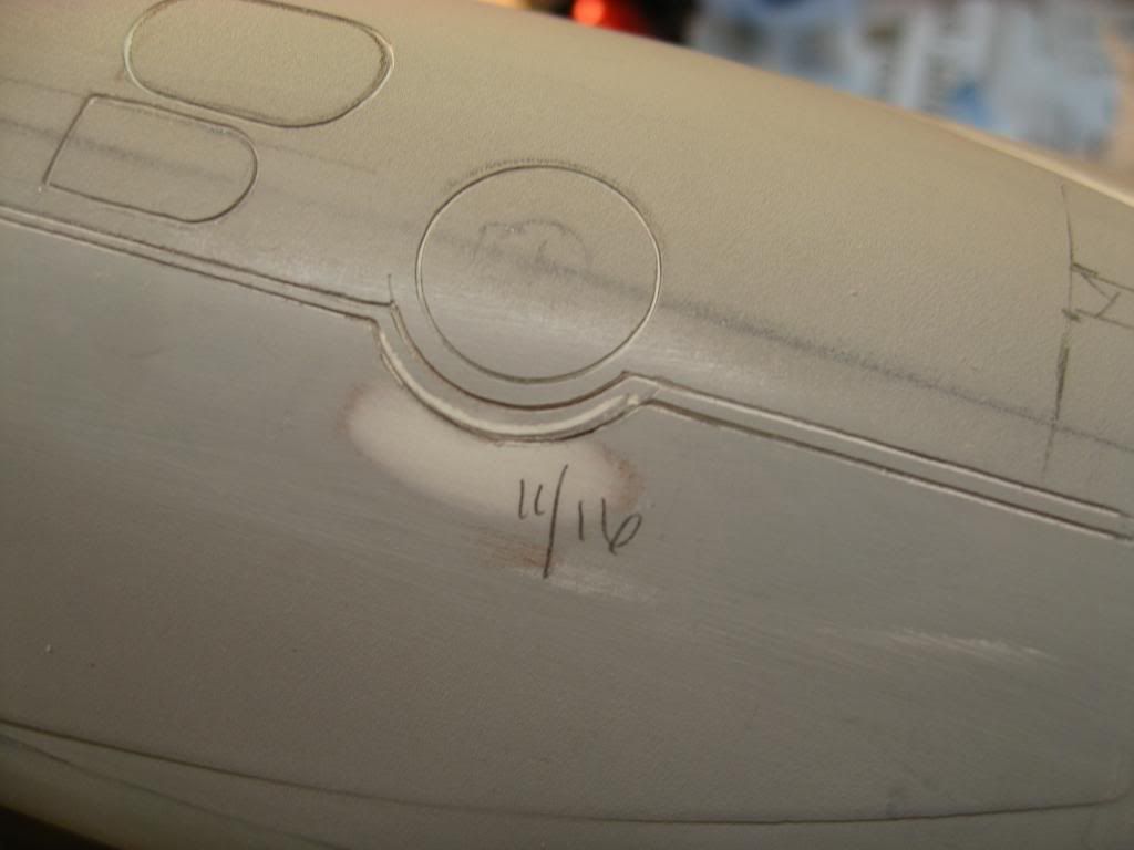
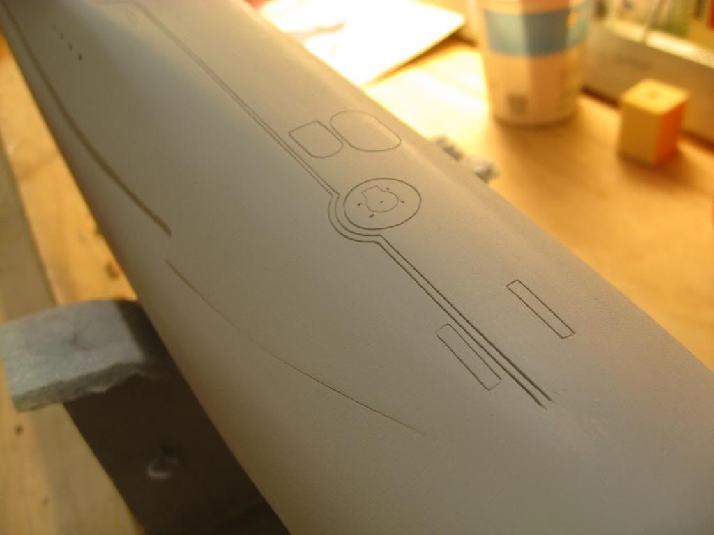
    After sanding and shaping the array began to look pretty good compared to the photos.


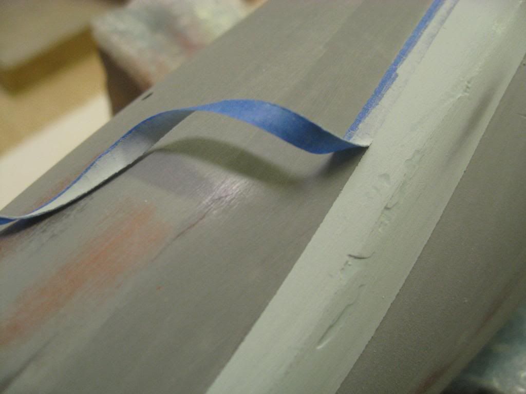
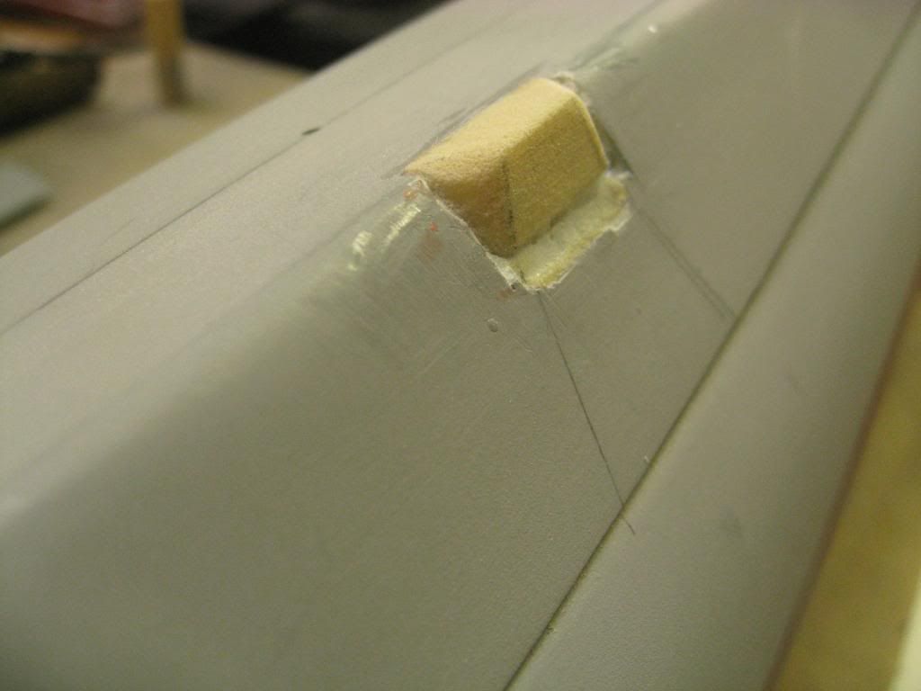
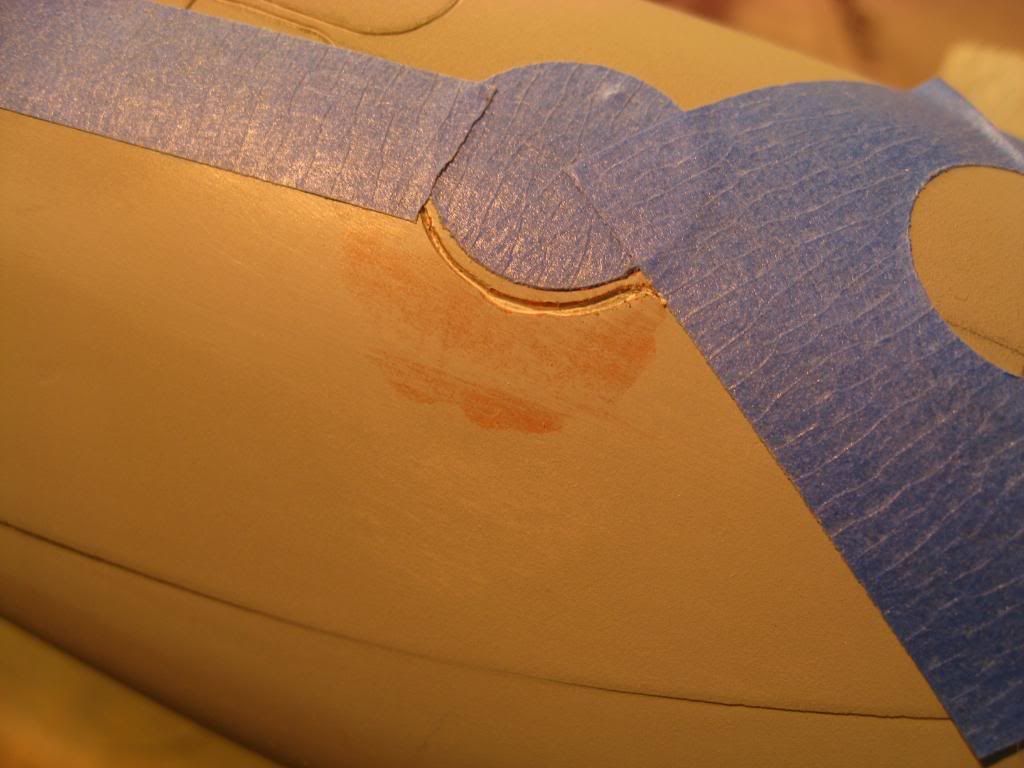
    When it looked like I thought it should I pulled the last of the tape away from the filler to reveal a sharp edge depicting where the fairing intersected the hull. There were several holidays that needed filling but that was easily corrected.


    I’ll have more later on the problems I had with the intersection of several compound curves where the fairing, the hull and the superstructure meet. That was a real challenge.


    “Will” Rogers
    SSBN659

    Comment

    • wlambing
      SubCommittee Member
      • Feb 2003
      • 848

      #17
      Re: MODELING THE USS WILL ROGERS

      Bill,

      The Towed Arrays were installed as overhaul drydocking opportunities allowed. I overhauled SSN 671 in EB (1974) and one d.dock was full of superstructure parts for boomers, I specifically recall a shipping tag assigning the new reel covering section for above AMR 1 to SSBN 617. 4 years later I overhauled SSBN 634 (2nd O/H) in Portsmouth and that's when we got ours. Always thought it was funny 'cos A-gang had the hydraulics, and a pre-req. to attend "Fleet 3000 PSI Hydraulic School", which didn't exist!!! Go to SubScol for training and get sent back 'cos they didn't know why you were there!! Your tax dollars at work!!!!!

      Take care, and good luck with your project!

      Bill

      Comment

      • bill rogers
        Junior Member
        • Sep 2003
        • 90

        #18
        Re: MODELING THE USS WILL ROGERS

        Thanks for the info Bill. I assume the motor for the reel is right there under the cover also. Or is the reel hydraulically driven?

        "Will" Rogers
        SSBN659

        Comment

        • wlambing
          SubCommittee Member
          • Feb 2003
          • 848

          #19
          Re: MODELING THE USS WILL ROGERS

          Bill,
          Yup! The hydraulics unit hung in the overhead of AMR 1 U/L Stbd side, just aft of the hovering hydraulics station. A shaft went through the hull to the reel up in the superstructure. The reel was horizontal and the cause of the extra jog-out along the edge of the main deck.

          Take care,

          Bill

          Comment

          • bill rogers
            Junior Member
            • Sep 2003
            • 90

            #20
            Re: MODELING THE USS WILL ROGERS

            After making the fairing for the towed array I started the “hump” that I found in a couple of photos below. I didn’t know what this was until posting a picture of it and asking the question. Turns out this was the cover for the towed array reel which is located outside the pressure hull but inside the superstructure. I also found out the towed array and reel covers were added later in life as the boats went into overhaul and drydocking. That explained why some photos showed boats with and some without the array. Anyhow, here are the “humps” (the reel covers).


            Since the drawings I had did not show the reel cover I had to “guestimate” it’s size and shape from the photos. I taped a piece of sandpaper to the superstructure and used a piece of scrap Renshape to match the curvature needed. The black lines mark the plan view of the cover. After getting the curvature I cut and sanded the piece to get the final shape.


            After attaching the piece I taped (there’s that tape again – it really is versatile!) around it to protect the superstructure as I finish sanded to get the curvature shown in the photos.

            Then I looked at the photos again and realized the reel cover didn’t look right. It was too wide. Close examination of the photos showed the width of the reel should have been just about the same width as the missile hatch covers.


            There was only one thing to do, chisel the first try off start all over again. I hated to do it but there was no good option.


            The next photo shows how much smaller the second piece is and the lines I laid out to get the angles right.


            It took some filling and sanding but after several tries I think it is pretty darned close to the reel thing (pun intended). And yes, there still is some minor fill in needed but the major work on the reel cover is done.


            So far in this project I’ve learned:

            1. It pays to do your research before starting,
            2. Don’t be afraid to make mistakes,
            3. Don’t be in a hurry,
            4. Be critical of your work, and
            5. Take a break now and then so the project doesn’t overwhelm you.


            “Will” Rogers
            SSBN659

            Comment

            • bill rogers
              Junior Member
              • Sep 2003
              • 90

              #21
              Re: MODELING THE USS WILL ROGERS

              In this post I’ll cover the “Buick holes” as they were sometimes referred to. That’s for those of you who remember the Buicks from the 50’s. For those of you don’t, the holes are for the explosively deployed evasive device launchers. I think that’s close but please feel free to correct me. As you can see this drawing of Simon Bolivar does not show the “holes”.


              Perhaps these were also installed later in the boat’s life. The cover picture of SSBN659 on issue 41 of the SubCommittee Report confirms USS Will Rogers had them so I’ll represent them on my model. But the question in my mind was how?

              The answer was “ Back to my research.” The photo below of one of the SSBN’s on drydock gave me the detail I needed. I won’t won’t name the boat for obvious reasons but take a real good look at the photo. Just below the forward end of the sail you can see the “Buick holes”. You can also see the axis of each opening is angled down and outboard from the boat’s centerline axis. Also, two openings are aft the forward end and two are forward of the sail.


              Using my “guestimates” of the angles I laid out and drilled the holes on both sides of the boat.


              Then I inserted styrene tubes and lined them up for glueing using toothpicks as shown. This allowed me to step back for a realty check before making them permanent.


              Once the glue had set I cut off the tube ends and filled around them and sanded them smooth. The final product looked realistic as far as I could tell.


              In my next post I’ll show how I did the rudders and stern planes.

              “Will” Rogers
              SSBN659

              Comment

              • bill rogers
                Junior Member
                • Sep 2003
                • 90

                #22
                Re: MODELING THE USS WILL ROGERS

                Masters for the rudders and planes were formed from balsa wood using some latex paint for sealer and for identifying spots needing more work. Later the masters were sprayed with gray primer and mounted on bamboo skewers for easier handling.


                The masters were laid in a bed of clay with dowel rods positioned for pouring and venting the silicone rubber. For the containment box I made up 4 L shaped pieces of 1/4” MDF and clamped them to fit the clay bed. The masters and the L shaped pieces were waxed and polished several times and then spray with mold release before pouring the silicone rubber. The L shaped pieces can be positioned to fit a number of different shapes and sizes.


                After the first pour of rubber had cured the clay was carefully removed and the masters readied for the second half of the pour. Mold release was applied to the masters and the box before the pour.


                The finished stern planes were positioned on the hull and an outline of the joint marked with a “Sharpie”. The contact surface was roughed up with my Dremel and a mask made of blue painters tape. With the mask in place to protect the hull the stern plane was epoxied to the hull and supported with tape until the epoxy cured. The photo shows the starboard plane already attached with the outlet tube of the towed array in place. The port stern plane is yet to be attached.


                This photo shows both stern planes attached and the after end of the towed array in position but yet to be sanded into it final shape. The styrene tube has not been glued at this point. That will be one of the last steps in finishing the model. Little pieces like this are too easily broken off while working on the model. The opening in the hull is a signal ejector located on the port side just forward of the stern plane.


                I tried a different approach to attach the rudders. The outline of the rudder connection with the hull was laid out and then covered with clear hockey tape. Why hockey tape? Because I had some and it was clear. Simple as that. Then I mixed up some Easy Sand filler and spread it on the clear tape followed by the rudder secured in position. Once the filler cured the base of the rudder had a curvature for a better fit to the hull. The clear tape was removed and rudder epoxied to the hull.


                For some reason the lower rudder was a bit too short so rather than create a new master I taped a dam around the base and filled it with epoxy as shown in the next photo. The clamp was used to hold the rudder upright.


                The epoxy brought the rudder back to where I should have made it in the first place. From here the rudder base was shaped and attached the same way as the upper rudder. I could have used filler instead of epoxy to get back to the original dimension but I thought epoxy would be stronger. It was also quicker than using filler.


                While all this was going on I was being closely watched by my constant companion Caper. She follows me just about everywhere I go and doesn’t correct me when I make a mistake.


                With the rudders and stern planes attached, the towed array and the reel cover in place the boat is beginning to look like I want it to look.


                “Will” Rogers
                SSBN659

                Comment

                • solo
                  Junior Member
                  • Apr 2009
                  • 32

                  #23
                  Re: MODELING THE USS WILL ROGERS

                  Waouh !!! Véry good job bill, fantastic

                  I built the "SSBN 642 Kaméhaméha" based Engel kit, here are some pictures of my work


                  Uploaded with ImageShack.us


                  Uploaded with ImageShack.us


                  Uploaded with ImageShack.us

                  Comment

                  • bill rogers
                    Junior Member
                    • Sep 2003
                    • 90

                    #24
                    Re: MODELING THE USS WILL ROGERS

                    Nice boat SOLO, the Engel kit is a very popular one. I had considered it as the platform for my Will Rogers but decided to do a scratch build in a smaller scale.

                    "Will" Rogers
                    SSBN659

                    Comment

                    • bill rogers
                      Junior Member
                      • Sep 2003
                      • 90

                      #25
                      Re: MODELING THE USS WILL ROGERS

                      Once the hull was looking like I wanted it to look I spent a lot of time thinking about how I would scribe the main deck details, particularly the serpentine shape of the safety track. Had the safety track just been two straight parallel lines there would have been no problem. On a previous model I soldered two needles together and easily scribed a straight track. But because of the curving track I felt this tool would not work well on this model. I decided to use only scribing tool for both lines but for this I needed a special template.

                      I copied a section of my drawing and darkened the track with a black felt tip pen so I could see the track better.


                      Then I glued the drawing to a piece of clear plastic using a spray adhesive from 3M. With my Dremel tool I cut close to the final line as shown below.


                      Finally I hand sanded down to the line checking frequently to make sure I didn’t over sand. (What you see in the picture is the second attempt because I did over sand the first piece I made.) Notice how close the safety track comes to the missile hatch cover.


                      The next step was to make a template for the hatch covers. For this I used a piece of 10 mil styrene, a circle temple and a straight edge. Except for the safety track all my templates were made from a combination of circles, squares, rectangles and straight lines. To avoid scribing problems with the distance between the safety track and hatch covers I made the hatch cover diameter 2 millimeters smaller than shown on the drawing.


                      When making a custom template it helps to lay out the details on a piece of paper to make sure it looks right before making any cuts. Once the template looks good on paper I lay it out on the styrene and tape it down to a piece of melamine board.


                      Depending on the shape to be cut I use a scriber or an “Exacto” blade. In the picture below I used a scriber tool to carefully “cut” out the template for one of the torpedo doors. I’ll use the same template for uniformity when I scribe all 4 doors.

                      In some cases I use a draftsman’s eraser template for difficult shapes.


                      Once the templates have been made and the longitudinal centerline penciled in, each detail to be scribed is laid out in pencil on the main deck while it is still in gray primer. This is a very important step as you can see by the changes I made in pencil in the pictures below. If it isn’t right in pencil, it won’t get any better after scribing. Make sure you measure carefully off the centerline and longitudinally. At this scale (1/120) I like to measure in millimeters because it’s easier for me to think millimeters than eighths, sixteenths, etc.


                      In my next post I’ll go into how I scribed the details on the main deck and cover how I corrected some scribing mistakes.

                      “Will” Rogers
                      SSBN659

                      Comment

                      • raalst
                        Senior Member
                        • Feb 2003
                        • 1229

                        #26
                        Re: MODELING THE USS WILL ROGERS

                        Hi Bill, thanks for not only showing the result but also how to get there !
                        keep snapping those pictures.

                        Comment

                        • bill rogers
                          Junior Member
                          • Sep 2003
                          • 90

                          #27
                          Re: MODELING THE USS WILL ROGERS

                          Thanks Ronald, I'll do my best to keep the pictures coming. Here is one of the pictures I have of the prop on SSBN633. Although I'm not ready for the prop now, I'm looking for ideas/suggestions on building one for this model. Keep in mind the scale of my model is 1:120.


                          Thanks for any ideas or suggestions,

                          "Will" Rogers
                          SSBN659

                          Comment

                          • bill rogers
                            Junior Member
                            • Sep 2003
                            • 90

                            #28
                            Re: MODELING THE USS WILL ROGERS

                            In this post I’ll show how I scribed some details on the main deck including how I corrected some mistakes caused by not taking my time. It’s the scribing that really improves the look of the model and the excitement in seeing it come together can lead to some careless mistakes. The mistakes can be corrected but it takes time and patience. Had I been more careful when scribing I would have saved myself some extra work.

                            Here are the tools I am using. From left to right are: a commercial scriber, a compass with a sharp point, a needle taped to a dowel and a toothbrush for cleaning out the details as they are scribed. In the upper left corner is a piece of 400 grit paper for keeping the tool points sharp


                            For correcting mistakes I use the “Easy Sand” and the “Glazing & Spot Putty”. The “Easy Sand” (from Caswell) is my favorite for larger corrections. It is an easy to work with two-part filler. The “Glazing & Spot Putty “ requires no mixing, is easy to work with but in my opinion doesn’t hold up as well.


                            Once I’ve laid out the details in pencil I tape my template to the model to hold it in place while scribing.


                            I use light passes with the tool, maybe 20 to 25, frequently brushing out the dust with the tooth brush and sharpening the point of the tool with the 400 grit paper. Each pass cuts a little deeper.


                            Check out David Merriman’s Cabal Reports and videos for more extensive details and tips on scribing.

                            In this picture you can see a couple mistakes I made on the safety track at the forward hatch. The curved track lines are too wide compared to the straight track. Also, I’ve accidently scratched the hull when I was cleaning some dust out with the tool. If you look carefully you can also see I’ve already made one attempt at correcting the mistake using the “Easy Sand”.


                            I think tried three times to fix the mistake before I finally got it right. Here you see how I covered the hull with blue tape to keep the filler confined to the spot I was trying to fix.


                            There, that looks better. By the way, the two long rectangular cuts at the forward end are for the retractable cleats. I plan to use HO gauge railroad tie spikes to represent the cleats deployed. We’ll see how that works later.


                            Scribing the torpedo tube doors has been a challenge. I first tried David Merriman’s trick of heating a piece of styrene to mold its shape to the bow and then cutting out the door shapes for a scribing template (Cabal Report) but at 1]http://i345.photobucket.com/albums/p392/SSBN659/USS%20WILL%20ROGERS/IMG_6332.jpg[/img]

                            Then I came up with a somewhat oddball mounting for working the hull in the vertical position. It was much easier to work this way.


                            Here you see the template taped to the hull ready for scribing the first two doors. When the bottom two doors were finished I repositioned the template and scribed the two top doors.


                            Now that the hull details are finished it’s time to move on the sail. I actually started the sail months ago but set it aside to complete the work on the hull. I’ll cover the sail in my next post.

                            “Will Rogers”
                            SSBN659

                            Comment

                            • solo
                              Junior Member
                              • Apr 2009
                              • 32

                              #29
                              Re: MODELING THE USS WILL ROGERS

                              Bravo Bill

                              It is the work of Swiss watchmaker

                              Comment

                              • bill rogers
                                Junior Member
                                • Sep 2003
                                • 90

                                #30
                                Re: MODELING THE USS WILL ROGERS

                                Merci SOLO.

                                "Will" Rogers
                                SSBN659

                                Comment

                                Working...