Attention all registered users. The new forum upgrade requires you to reset your password as you logon for the first time.
To reset your password choose this option that is displayed when you attempted to login with your username: "Forgotten your password? Click here!"
You will be sent an e-mail to the address that is associated with your forum account. Follow the simple directions to reset your password.
If this is your first visit, be sure to
check out the FAQ by clicking the
link above. You may have to register
before you can post: click the register link above to proceed. To start viewing messages,
select the forum that you want to visit from the selection below.
Well I did some prototyping for about 8hrs yesterday and finally came up with a system for the rudder that I like.
First I made a foundation to strengthen the rudder.
Then after making several configurations for linkages that didnt give me the rudder swing I want, I remembered some pictures I have of the linkage Kevin Mc made for his Oscar II.
I then made a mock up working version and got it working like a champ.
I notice that with your linkage configuration the inner rudder will always throw more than the outer rudder in a turn- was this delibarate? If you want them them to move the same amount a slight tweak to your control horn/linkage setup is all that's required.
Look at the control arms in the above photo, taking notice of the fact that the hole in the contol arms are to the right of the red line. If you want each rudder to have the same amount of travel the hole in the contol arms should line up precisely under the red line when at neutral. More throw on the inner rudder is the result of the control arm configuration you've made. If for some reason someone wanted more throw on the outer rudder, the linkages ought to be configured so that the hole in the contol arms sits to the left the red line when at neutral.
Can you tell I have a thing for carefully done linkages? (If anyone's got a photo of the linkages I designed to raise the masts on my OSCAR, that will remove any doubt!)
It is true one rudder has more swing in one direction then the other. I made the slight off set so I could get more swing out of the control horn. If you look at the yoke, it will only have a little bit of travel before dead ending against the hull. To compensate I moved the horns back wards so I could use the full swing of the servo. I think I will still get a good turn out of her like this though.
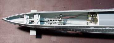
There will be. You are basically looking at the intermediate molds for the type VII that I made. These are made to make sure everything works and there are no install issues prior to final molds.
Started making the drive line components and ran into an interesting problem problem because of the way I chose to insert the cylinder. It is basically impossible to line up 2 dog bones and insert the cylinder at the same time. To compensate I made spring loaded drive shafts that I can compress and then put into place.
I also made the Cylinder restraints which consist of velcro and a screw to prevent axial movement.
Initial pool test have shown me that this boat hauls butt. Its like watching a knife cut through butter when the knife is at 2000 degrees F.
I do need to redo the bow plane mechanism because it is not very fluid. I am also not very happy with the swing of my dive planes so, I will have to shorten the control arm a bit.
Well I got the stern plane linkage shortened up as much as it is going to go and I have re routed the bow plane linkage over the top of the cylinder. This worked much better then bellow because the angle to the control horn was much better. I also beefed up the brass tube size to make a more rigid linkage. All that is required to remove the cylinder is to move the linkage from the kil kon and fold the linkage forward.
The boat is also all trimmed out and I am happy to say that i was able to achieve a great submerged trim and a very good surface trim. The aft end is off by about 1/4".
I also realized I never showed how I did the top of this model. First I reinforcing the under side of the deck. To do this I laid the deck on top of some thicker sheet styrene and traced out the top onto the styrene. I then cut the styrene out but I cut it out a bit inside the given line so that the styrene would not interfere with the indexing lip when installed.
I then glued the thing together using CA to spot bond it then Plasti weld to finish it off.
I also added an indexing lip to the front and sides of the little drop down areas. The drop down areas actually help hold the whole deck down because of the angle. I also added an indexing lip to bottom hull aft. I then drilled and counter bored the aft top for the screw.
I also decided to go with the 1 inch left and right rabosh props supplied in the type 7 package deal. After some testing this props turn out to be way more then adequate. Not to mention a lot easier.
I also wanted to show a neat way to open up all the flood vents that I picked up. I basically held the sides up to the light and traced where the floods were on the inside. I then took the dremel with a sanding disc ( carbide cutter works better) and removed enough material to open up all the vents. I did this for all the vents.
Also a little more detail on the stern tube supports an hull throughs.
These were a simple task of drilling them out to 1/8" and then taking a file and making them a proper fit. I also traced the tubes on the boat and then cut a hole in the hull just smaller then the outline I made.
Here are some other tip and tricks I left out earlier.
Making the Sub Driver saddles for this boat was very easy. The kit iteself comes with two support structures for the forward and aft end of the boat. Since these were big enough to hold a Sub Driver in them I simply took one of my sub driver end caps and traced it onto the supports, ensuring the same distance from the bottom of the keel was used. It is also a good idea to get in as low as possible so you have some clearance and a better chance of getting the decks above the water when surface. Just make sure you do not make it so close that the material become weak. Not only are they holding your sub driver snug but they are also adding structural strength. After all that I used a ban saw with a thin blade and cut them up and glued them in place.
I also think it is a good idea to go over how I assembled the dive planes and linkage.
The first thing to do is to thin out the inside walls off the dive plane area before assembling the model halves ( I know why are you just saying this now? Hey Im not perfect!) I did this part using a file and scraping the plasic away a little at a time, using the forward edge of the file. This will work but, its also very slow. The easiest way is to use a dremel and a round carbide cutting bit. It also will leave a better finish. The key is to no take to much off but just enough so you can get a control lever in there. Hold it up to the light to try and gauge you thickness. Also, having a finger behind the back I find assists.
Make sure you use your control arm as a gauge to figure out if you've taken enough away.
It is also a good idea to round down that edge so see in the picture a bit. This will give you a little more room to get a shorter swing arm in there.
When I was making the dive planes I wanted to make it so that the whole thing could be taken apart for repair. You just never know when your going to have to take her down to parade rest. To ensure this would be a possibility I used square brass as my rods when I molded the planes. This way I would only have to slide them through another square brass and I wouldn't have to worry about getting a set screw in there.
To make the dive plane control arm I took a piece of thin brass plate and drilled a hole in it large enough to pit a piece of brass square tubing that would slid over my dive planes control rod. After i got it in the hole i soldered it in and then trimmed the whole thing down to get the bare minimum required for operation. The bottom of the ting is defiantly at its minimum.
Well Been doing lots of painting. Not my favorite task because I am generally not very good at it. More then likely due to the fact that I am very impatient.
So here it is. I am not a type 7 expert by a long shot and I basically took the paint scheme from a combination of other boats I saw. If you have input or correction please provide them so I can make it look better. It is not modeled after any particular boat.
I also tried a new paint technique. I tried to get a faded looking wood deck so I first painted it a light wood color and let it dry. I then went back over with a very dark grey that has been thinned. Let me know what you think.
I also need to make another attack periscope for this boat and install it. This boat is super fragile and it is starting to get to me. I finally just broke off the little struts that go tword the rudders and stern planes. I figured they would get broken of eventually and I might aswell just fix it now.

 Tweet
Tweet


Comment