
Well, I've finally started the actual building of a 1/96 scale Ohio class. With the help of EB dockside plans from Don Evans, and input from many current and past SSBN crew members, updated and what I'm told are very accurate plans have been developed. Now the building can begin.
Plans are to build a master that's ready by the '07 Sub Regatta. From that, molds will be made, and multiple reproductions should be available by '08. I'm not going to take any orders until all the molds are done. But I may start a waiting list once the master is finished. If you would be interested in a model like this, go ahead and chime in. The more enthusiasm there is out there, the more I'll have, and the faster I'll build.
If any of you have seen my Seawolf and Virginia, you've seen models where the masters were made by turning wood hulls on a lathe. Even at their size, the Virginia was still too long for my lathe, so I only turned the tapered bow and stern sections, and was lucky enough to find a PVC pipe with the exact diameter needed to fill in between. Well, this puppy is a whopping 70" from stem to stern, and there ain't no way I'm going to turn that on a lathe. Not to mention, with the missile deck transitions on the Ohio, that wouldn't work too well anyway.
So for this model build I have taken a que from Kevin McLeod and the very large Oscar II that he made. I'll be using the foam sectioning technique with a few simplifications for shaping the foam to get irregular contours easier. Let's begin.
I started with the 2D plans and developed cross sections that would match the 9/16" and 1-1/2" thick construction styrofoam that I had, and is the easiest sizes to get. In the photos the blue is 9/16 and the pink is 1-1/2.
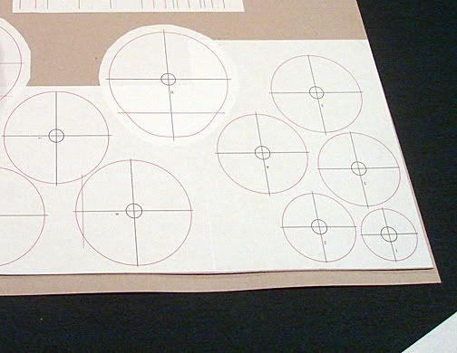
Here you see my first mistake. Because the foam body of the master will be coated with plaster, and eventually a epoxy resin and glass shell, these cross sections don't account for the added thickness. So I drew circles 1/16" inside the actual exterior circles and printed them out and pated them down. Steve Neill says he uses old cereal boxes for a cardboard to paste them on to. Well, I don't eat enough cereal, so I got some thin gray chip board form my local art supply store to use.
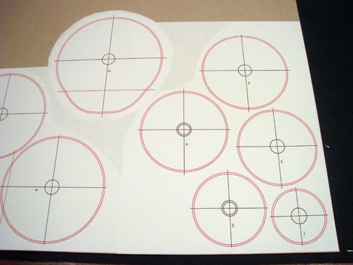
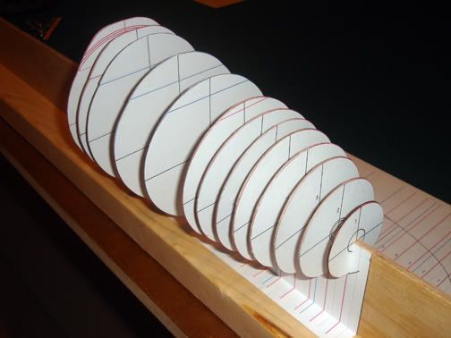
The next step is to cut all of these out. They will be used to sandwich a piece of styrofoam between, with each side registered to the other. Then they become cutting guides for the hull contour. You'll see later.
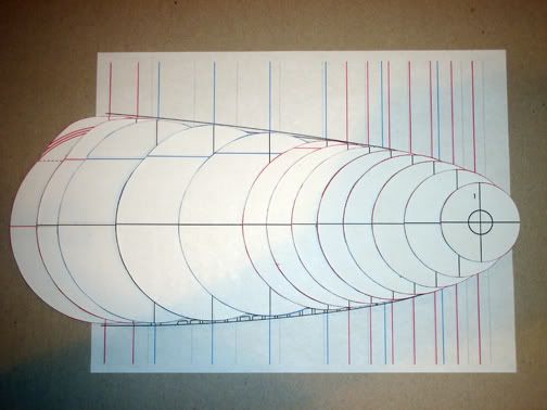
After cutting out the cross sections, I then cut a slot up the center of each the width of the spineboard I am using. This slot goes up to the center line on each, and by that resting on the top of the spineboard every piece will be registered to one another. I then coated the edge of each with super glue to make them hard. Then the foam cutting wire will be able to travel over the edges without burning or cutting them.
Here they are lined up on the spineboard. I Super77'd a plan profile to the side of the spineboard which shows me where each section should go for a guide.
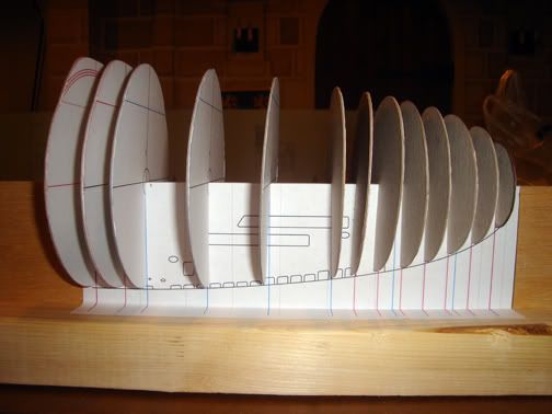
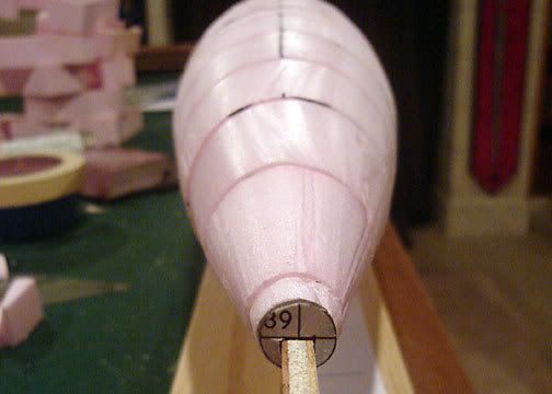
From a 3/4 angle, you can start to see what the 3D piece will look like. And you can even kind of check your work at this point. If something is dramatically wrong, like a cross section is missing, you'll see it here and hopefully save some cutting and frustration.
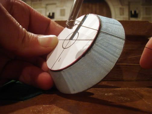
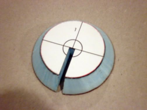
For the foam sandwiches I glued one cross section to one side of the foam. Then on a bandsaw (because that's easiest) I cut out the slot for the spineboard. The I glued (Super77) the next cross section in the sequence to the other side of the foam by lining up the slots. With a hot wire knife against the edges of both sides you can cut the foam center to a straight-line contour of each section. I take the cross-section templates off each foam piece once they're cut by using rubber cement thinner to unstick the Super 77.
Once all the sections are cut, they can be assembled on the spineboard in order, checked with the plan underneath, then Super 77'd to one another.
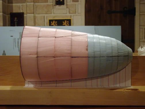
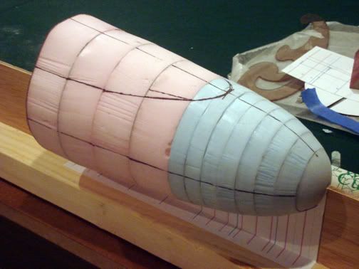
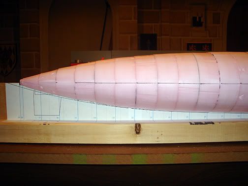
Here you can see them together, now really beginning to take on the distinctive shape of the Ohio bow with the missile deck beginning.
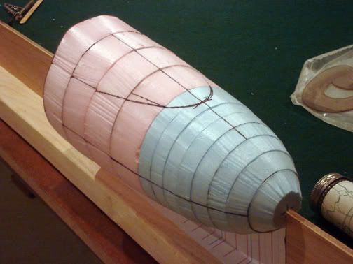
With a little light sanding from one of those sponge sanfing blocks, the shape can be further refined. Don't sand away all the high edges, they'll be used to determine the depthe of the plaster coating later.
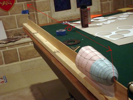
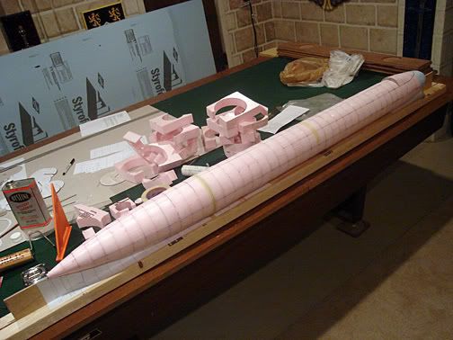
So far I've only got the bow back to where the missile deck fairwaters begin done. In this photo I give you an idea of how big this sucker will be. Ain't it perty?
More as it gets done.
Pete
Plans are to build a master that's ready by the '07 Sub Regatta. From that, molds will be made, and multiple reproductions should be available by '08. I'm not going to take any orders until all the molds are done. But I may start a waiting list once the master is finished. If you would be interested in a model like this, go ahead and chime in. The more enthusiasm there is out there, the more I'll have, and the faster I'll build.
If any of you have seen my Seawolf and Virginia, you've seen models where the masters were made by turning wood hulls on a lathe. Even at their size, the Virginia was still too long for my lathe, so I only turned the tapered bow and stern sections, and was lucky enough to find a PVC pipe with the exact diameter needed to fill in between. Well, this puppy is a whopping 70" from stem to stern, and there ain't no way I'm going to turn that on a lathe. Not to mention, with the missile deck transitions on the Ohio, that wouldn't work too well anyway.
So for this model build I have taken a que from Kevin McLeod and the very large Oscar II that he made. I'll be using the foam sectioning technique with a few simplifications for shaping the foam to get irregular contours easier. Let's begin.
I started with the 2D plans and developed cross sections that would match the 9/16" and 1-1/2" thick construction styrofoam that I had, and is the easiest sizes to get. In the photos the blue is 9/16 and the pink is 1-1/2.
Here you see my first mistake. Because the foam body of the master will be coated with plaster, and eventually a epoxy resin and glass shell, these cross sections don't account for the added thickness. So I drew circles 1/16" inside the actual exterior circles and printed them out and pated them down. Steve Neill says he uses old cereal boxes for a cardboard to paste them on to. Well, I don't eat enough cereal, so I got some thin gray chip board form my local art supply store to use.
The next step is to cut all of these out. They will be used to sandwich a piece of styrofoam between, with each side registered to the other. Then they become cutting guides for the hull contour. You'll see later.
After cutting out the cross sections, I then cut a slot up the center of each the width of the spineboard I am using. This slot goes up to the center line on each, and by that resting on the top of the spineboard every piece will be registered to one another. I then coated the edge of each with super glue to make them hard. Then the foam cutting wire will be able to travel over the edges without burning or cutting them.
Here they are lined up on the spineboard. I Super77'd a plan profile to the side of the spineboard which shows me where each section should go for a guide.
From a 3/4 angle, you can start to see what the 3D piece will look like. And you can even kind of check your work at this point. If something is dramatically wrong, like a cross section is missing, you'll see it here and hopefully save some cutting and frustration.
For the foam sandwiches I glued one cross section to one side of the foam. Then on a bandsaw (because that's easiest) I cut out the slot for the spineboard. The I glued (Super77) the next cross section in the sequence to the other side of the foam by lining up the slots. With a hot wire knife against the edges of both sides you can cut the foam center to a straight-line contour of each section. I take the cross-section templates off each foam piece once they're cut by using rubber cement thinner to unstick the Super 77.
Once all the sections are cut, they can be assembled on the spineboard in order, checked with the plan underneath, then Super 77'd to one another.
Here you can see them together, now really beginning to take on the distinctive shape of the Ohio bow with the missile deck beginning.
With a little light sanding from one of those sponge sanfing blocks, the shape can be further refined. Don't sand away all the high edges, they'll be used to determine the depthe of the plaster coating later.
So far I've only got the bow back to where the missile deck fairwaters begin done. In this photo I give you an idea of how big this sucker will be. Ain't it perty?
More as it gets done.
Pete


Comment