New Submarineworks Seawolf Build

Collapse
X
 
  • Filter
  • Time
  • Show
Clear All
new posts
  • bob_eissler
    SubCommittee Member
    • Aug 2005
    • 331

    #16
    Very nice Pete, great to see this going. Wish they were still having the Funrun this month so I could see it better. Can you make the pictures a little bigger, please?

    Comment

    • pirate
      Member
      • Oct 2005
      • 849

      #17
      Stern vents opened and filed out.

      Click image for larger version

Name:	DBF50E7C-17C1-4BC3-A6F8-8BA2F711E7BB.jpg
Views:	1
Size:	11.1 KB
ID:	134897

      Comment

      • pirate
        Member
        • Oct 2005
        • 849

        #18
        Bob,
        If I try to make the photos any larger it won’t take them.

        Comment

        • Ralph --- SSBN 598
          Junior Member
          • Oct 2012
          • 1417

          #19
          This is just a test on photo size display.

          When I save images, I make them 7" x 5.25" both horizontal and vertical at 100 dpi.
          Your image above is saved at 2.08" x 2.78" at 72 dpi.
          When I enlarged it, it pixalated.

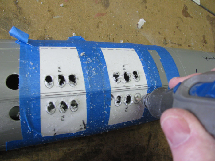
          Here is a test image of my Gato flood ports when I cut them in.

          Comment

          • pirate
            Member
            • Oct 2005
            • 849

            #20
            The next step is to create the Z-cut in the hull. This one cut in the bottom of the hill at the demarcation of the sonar done and one on the top hull just in front of the rudder. Here I show the cuts at the bow.

            Before I started, I duplicated one of the WTC saddles and cut it down to fit in the lower hull right at the cut line. What this will do is hold the leading edge of the hull behind the sonar dome at the width it is before the cut. Without this brace it is likely to warp or shrink the width and no longer fit the width of the sonar dome and no longer fit together flush.

            Click image for larger version

Name:	65E6AB99-0E81-4F59-8139-6D8451F320F4.jpg
Views:	2
Size:	9.3 KB
ID:	134925

            I also attached a rare earth magnet thAt will hold the hull together when close up and brass rod on each side as alignment pins to help the hull keep its shape when closed.

            Click image for larger version

Name:	D7577C27-0E0A-46C2-9F8F-85939AA5C00B.jpg
Views:	2
Size:	9.0 KB
ID:	134926

            The sonar dome cut from the bottom hull is then glued to the upper hull To make a one-piece sonar dome and create a “stop” point when the bottom hull is slid together with the top.

            Click image for larger version

Name:	8EE194A8-9508-4CFF-9610-7D478A2858BB.jpg
Views:	1
Size:	8.2 KB
ID:	134927
            Click image for larger version

Name:	75DB91CF-16D9-4D55-BE04-78B7C0702032.jpg
Views:	2
Size:	13.8 KB
ID:	134928

            Comment

            • pirate
              Member
              • Oct 2005
              • 849

              #21
              Click image for larger version

Name:	91DAD900-2AC0-4137-8FCD-F2B3C20357F5.jpg
Views:	2
Size:	9.3 KB
ID:	134929

              Click image for larger version

Name:	7D517506-8E06-482A-99CB-4940288BBC72.jpg
Views:	2
Size:	9.0 KB
ID:	134930

              Comment

              • pirate
                Member
                • Oct 2005
                • 849

                #22
                Yeah, doesn’t work. I choose actual mage size (3.4 MB) and it imports it at 553 KB.
                Photo upload tool automatically reduces the image size. Doesn’t matter if I click the photo icon or the paper clip icon to add images.

                Is ther another way to add photos?
                Attached Files

                Comment

                • pirate
                  Member
                  • Oct 2005
                  • 849

                  #23
                  Work on the stern.
                  Attached the rear of the top hill to the bottom then cut off the extra at a molded demarcation line to accept the pumpjet propulsor.
                  Click image for larger version

Name:	2F18D9D6-882E-4953-BC42-D62016F6E2D1.jpg
Views:	1
Size:	14.7 KB
ID:	134933

                  Held the pumpjet in place to check fit.
                  Click image for larger version

Name:	21DE50C0-D263-449F-A2AC-BE458525A8AB.jpg
Views:	1
Size:	14.5 KB
ID:	134934

                  Comment

                  • pirate
                    Member
                    • Oct 2005
                    • 849

                    #24
                    Bob, I just figured out. When you click or touch on a photo it brings it up in its own window. If you click on or touch that photo it pops up at actual size, or at least larger than the thumbnail.

                    Comment

                    • pirate
                      Member
                      • Oct 2005
                      • 849

                      #25
                      These are pictures of using an extra long brass rod to align the elevators and figure out where to attach them.
                      I used the same process of drilling small holes and then removing the material between them to cut out the slots to take the elevator roots on each side.
                      Click image for larger version

Name:	48C2EA80-8198-4FF0-8F49-6B33AADF60EF.jpg
Views:	1
Size:	9.4 KB
ID:	134935

                      Click image for larger version

Name:	EFBCD333-F035-4222-87D1-17F462C31D2C.jpg
Views:	1
Size:	11.7 KB
ID:	134936

                      Click image for larger version

Name:	6D0103DE-589A-4B3B-ABE0-E3E52C631883.jpg
Views:	1
Size:	13.2 KB
ID:	134937

                      Click image for larger version

Name:	40E8BE03-4913-4CA9-AD6B-410A2306C403.jpg
Views:	1
Size:	11.8 KB
ID:	134938

                      Click image for larger version

Name:	F919DE6B-1E4A-4FC6-B3C7-F0E69E49F581.jpg
Views:	1
Size:	13.2 KB
ID:	134939

                      Click image for larger version

Name:	A1E834EC-E084-4D33-B68E-CA7F2661F0AD.jpg
Views:	1
Size:	11.7 KB
ID:	134940

                      Comment

                      • pirate
                        Member
                        • Oct 2005
                        • 849

                        #26
                        Aligned the horizontal stabilizers with a brass rod threaded through the bushings I put in the shaft holes. Then I used a long drill bit through the outboard planes’ shaft holes to drill all the way across through the hull sides.
                        Attached Files

                        Comment

                        • pirate
                          Member
                          • Oct 2005
                          • 849

                          #27
                          Using a brass rod placed through the shaft holes for the rudders as a vertical guide, I leveled the hull and glued up the dihedral planes.

                          Once again, the amazing Lego blocks We’re used to hold the dihedrals in place.
                          Attached Files

                          Comment

                          • pirate
                            Member
                            • Oct 2005
                            • 849

                            #28
                            While waiting for the epoxy glue to dry on the dihedrals, I moved to the top hull to cut out some material under the sail and attach the sail.
                            I drilled holes for the attaching screws and made lines across the area centers on them. Then I aligned the sail and transferred the lines to the sides of the sail.
                            Carrying the lines to the bottom of the sail, I then drilled and tapped the screw holes. Then attached the sail to the top hull.
                            Attached Files
                            Last edited by pirate; 10-28-2020, 09:17 PM.

                            Comment

                            • pirate
                              Member
                              • Oct 2005
                              • 849

                              #29
                              Once epoxy cured on the dihedrals I also attached the horizontal plane roots with epoxy and a clamp.
                              Attached Files

                              Comment

                              • pirate
                                Member
                                • Oct 2005
                                • 849

                                #30
                                Aligning the prop shaft with the pump jet.

                                I positioned the shaft in the bushing on the pumpjet and placed it where it will go on the stern, then ran the other end into the bearing on a control bulkhead inside the bottom hull. This will make sure the pumpjet and the shaft is perfectly aligned straight with the hull. I used a small rule across the hull half to show where the center bearing needed to be. To get the tight spot the bulkhead had to move forward and back u til the shaft ended up in the tight place.
                                Click image for larger version

Name:	5EBDE4F5-2105-4319-9FAC-8D498B0464F0.jpg
Views:	1
Size:	19.0 KB
ID:	135091
                                Click image for larger version

Name:	7181BF94-E1F2-4D62-8191-C4B796B4F043.jpg
Views:	1
Size:	17.1 KB
ID:	135092
                                Click image for larger version

Name:	671A046C-53D0-4671-B3AD-B86E98168EFD.jpg
Views:	1
Size:	10.0 KB
ID:	135093

                                Then I epoxied the bulkhead in place.
                                Later I will epoxy the pumpjet on. But first I want to install all of the control linkages in the back without it in place so I can see in there from both sides.

                                Comment

                                Working...
                                X