Casting resin and removable rod

Collapse
X
 
  • Time
  • Show
Clear All
new posts
  • salmon
    Treasurer
    • Jul 2011
    • 2342

    #1

    Casting resin and removable rod

    I need help or suggestions. I am casting some dive planes and will need to have the final product with a shaft hole in it. The solution I have seen others do, is cast the piece with a brass rod in it. After the resin hardens, the rod is removed. So, what do I need to do to assure the rod will be released?
    (hopefully this makes sense, if not please ask me to clarify)
    If you can cut, drill, saw, hit things and swear a lot, you're well on the way to building a working model sub.
  • JWLaRue
    Managing Editor, SubCommittee Report
    • Aug 1994
    • 4281

    #2
    Tom,

    I'm not clear as to the desired end result..... Wouldn't the dive plane need a shaft of some sort embedded in it? What would be the purpose of the hole through the dive plane?

    -Jeff
    Rohr 1.....Los!

    Comment

    • Ralph --- SSBN 598
      Junior Member
      • Oct 2012
      • 1417

      #3
      Jeff has the same thoughts as I do.

      When casting control planes, the rod is put in place to be cast as the usable control rod.
      It is not usually removed.

      Take the time to figure out what size control shaft you will be using in your project.
      Make the mold to hold the rod in place.

      To keep the shaft from turning in the cast pieces, either grind a couple flat spots in the control rod or soldier a couple of small bumps on the rod.
      This will keep a straight through control rod straight.

      For rudders and sail planes where the control rod only exits one edge of the control surface, put a small bend in the end of the rod that will be in the casting.
      ----------------
      The question is, why would you need the control rod to be removed?

      Comment

      • thor
        SubCommittee Member
        • Feb 2009
        • 1479

        #4
        If you want the rod to be easily removed after you cast the object around it, simply rub a thin coat of vaseline on the rod. Make sure the rod is very smooth. Sand it with 1,200 grit sandpaper before coating and casting.
        Regards,

        Matt

        Comment

        • scott t
          Member
          • Feb 2003
          • 880

          #5
          Another thought would be to use a brass tube that stays in the casting. The brass shaft will
          slide into this tube. Glue the shaft to the tube with silicone and it might be adjustable or removable.

          Click image for larger version

Name:	Mel+Connector+1mt.jpg
Views:	1
Size:	34.7 KB
ID:	129695

          Comment

          • salmon
            Treasurer
            • Jul 2011
            • 2342

            #6
            Thank you all for your comments. Matt I will use vaseline. The dive planes have 3 parts to them, the plane itself (rod remains in that), the base (shaft travels through it and so will two screws, and the base (it goes inside the hull and offers support to the other two pieces). I will follow up once cast, if I remember too!
            If you can cut, drill, saw, hit things and swear a lot, you're well on the way to building a working model sub.

            Comment

            • JWLaRue
              Managing Editor, SubCommittee Report
              • Aug 1994
              • 4281

              #7
              Ahhh....Tom, what I do for dive plane components where a rotating shaft needs to go through is to cast a brass tube that has an I.D. that is (essentially) the same as the O.D. of the rod in the moveable part. This may be the same idea that Scott suggested.

              Also, I have moved away from using round rods for the dive planes and rudders. Instead I use square 'rod'....eliminates the problem with it rotating in place as well as allows for a permanently correct alignment with the servo control horn.

              -Jeff
              Rohr 1.....Los!

              Comment

              • bigdave
                Junior Member
                • Feb 2003
                • 3596

                #8
                Yes
                Square rods work well if it works for your design.
                A square peg will rotate in a round hole. BD
                sigpic"Eat your pudding Mr Land"
                "I ain't sure it's pudden" 20K

                Comment

                • salmon
                  Treasurer
                  • Jul 2011
                  • 2342

                  #9
                  Only in our world does this make sense BD! LOL
                  I already began the molding process, so rods it is for now. In the future, well, we will see what the future brings. I just need to live through this!
                  It is so fun to think of things to make for the sub to get it to work. Having a blast with it. If all goes well, I should have a Walrus running (maybe not painted) for the SubRonLA run in beginning of 2017!
                  If you can cut, drill, saw, hit things and swear a lot, you're well on the way to building a working model sub.

                  Comment

                  • salmon
                    Treasurer
                    • Jul 2011
                    • 2342

                    #10
                    O.K. Casting is moving along slowly.
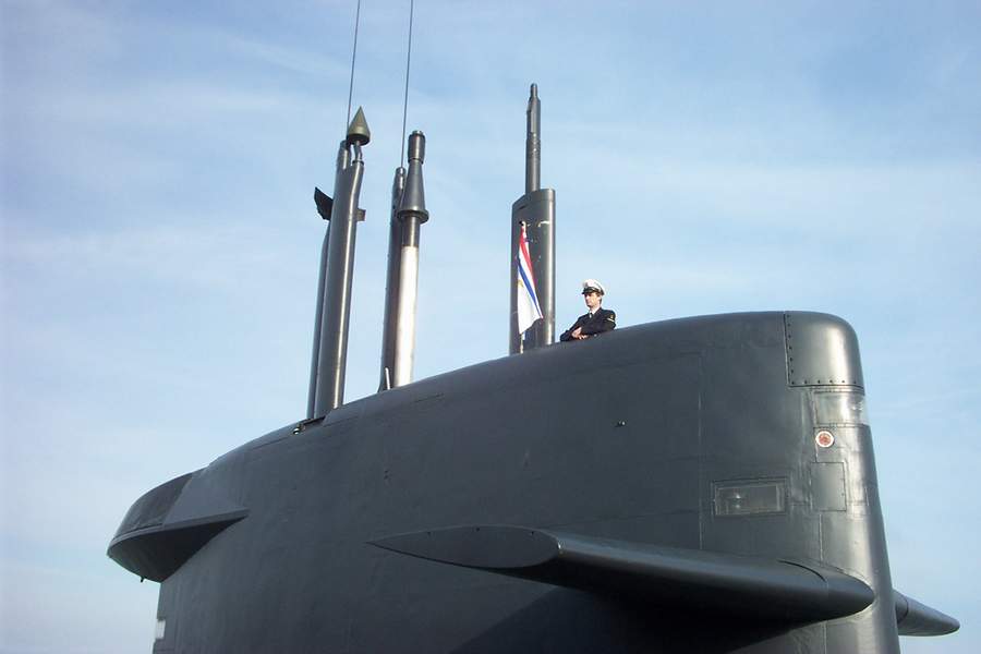
                    I have another issue. The set of planes I got did not have the sail planes. So, I venture into a new world of fabricating them.
                    Although in research, I have two plans:
                    This one shows a more modern sail (with exhaust diffuser)
                    Click image for larger version

Name:	Walrus Plans_003.jpg
Views:	1
Size:	53.8 KB
ID:	129711

                    And the ones from the original design:
                    Click image for larger version

Name:	Walrus Plans_004.jpg
Views:	1
Size:	67.0 KB
ID:	129712

                    I can find pictures of the original design, but many photos look like the first photo. Can anyone shed some light on this? Was there a change in sail plane design?
                    If you can cut, drill, saw, hit things and swear a lot, you're well on the way to building a working model sub.

                    Comment

                    • Ralph --- SSBN 598
                      Junior Member
                      • Oct 2012
                      • 1417

                      #11
                      I did a little looking.
                      I find lots of photos but not many that give a good view of the planes.
                      This one shows the planes clearly.


                      I shows how the planes meet the sail.

                      This photos shows basically the same thing but it has a shadow of the planes on the side of the sail that could help to scale the outside edge of the planes.
                      If you know the height or length of the sail, you can figure out the length of the plane tip.
                      https://www.flickr.com/photos/brian_digital/5311781885 (photo did not show up so I linked to it.

                      Looking at your two images, I think the bottom one is closer to the real planes except the front angle may be too much.
                      The front edge does not look to me as if it is straight like the top image but not so angled as the bottom image.
                      Maybe the shadow will help.

                      The rear edge appears to be straight i the photos I have looked at.

                      Comment

                      • salmon
                        Treasurer
                        • Jul 2011
                        • 2342

                        #12
                        Thanks Ralph. I agree it is hard to find definitive answer. Your assessment is where I am, is the bottom plans (which are from original plans) too swept back or are the newer sub's planes more like the top image? Or somewhere in between? Or the bottom plans accurate? Or.....well you get the idea.
                        If you can cut, drill, saw, hit things and swear a lot, you're well on the way to building a working model sub.

                        Comment

                        • Ralph --- SSBN 598
                          Junior Member
                          • Oct 2012
                          • 1417

                          #13
                          The Walrus class had four boats built.
                          Last one, launched 1994.
                          The replacement for the Walrus is not scheduled until 2025.
                          So, thinking that a "newer sub" might have different sail plane shapes does not look likely.
                          -----------
                          I have found both drawing that you have as a reference.
                          Not sure of the source for the top image, though it comes up at various sites as a building drawing.

                          The bottom image is from a 1/350 scale model plan.


                          No real information to use.
                          I have been there....

                          Comment

                          • subdude
                            Official Peon
                            • Feb 2003
                            • 682

                            #14
                            Tom, just a thought to bear in mind. It is very, very difficult to accurately determine the actual dimensions of something from a photograph, especially if there is any sort of angle involved. The angle of the lens to the object, and in this case the angle of the shadow on the sail, along with the relative distance from the lens will produce some very, very strange results.

                            A large part of my job involves attempting to validate dimensions of machine parts by way of photographs. I could show you images where you would swear that 2 items in the photo are the same size when one is actually more than twice the size of the other.

                            Trust, but verify if at all possible.

                            Jim
                            SubCommittee member #0069 (since the dawn of time.....)

                            Comment

                            • Guest

                              #15
                              Different class of boat, but a lineage to the Walrus which may help.

                              Click image for larger version

Name:	planszwaard2.jpg
Views:	1
Size:	98.3 KB
ID:	129713

                              Comment

                              Working...