HMS Repulse 1/96 RC scratch build

Collapse
X
 
  • Time
  • Show
Clear All
new posts
  • steveuk
    Junior Member
    • Oct 2005
    • 467

    #16
    Hi Dave, I spent some time looking over your hull. As I mentioned before you are very close with your detail. The main issue as far as I can make out is that your missile hatches end too soon, they need to end further back. In order for this to happen you will need to widen your missile hatches so that they take up more deck. Problem is you also need to try to maintain the missile hatch length to width ratio. Which leads me to suspect that your missile deck maybe is narrow. Jecobin plans also suffer from missile deck being too narrow. Still, you might get away with it by widening your hatches. Try drawing it out roughly on your deck. I have also taken the time to outline other areas of adjustment which would make your model more accurate. These are only my opinions though. Having no plans and just going by photos is always going to be subjective.
    Differences between the four sister ships definitely. Res gets just her tower tiled no tiling on her hull. Revenge appears to have just been painted with rubberized paint. Repulse and Renown get the whole treatment tiled tower and hull, although there are slight differences in the tiling patterns and also bow sonar covers differ slightly.
    Anyway, see what you make of my edit of your model hull photos below.
    Attached Files

    Comment

    • Davidh
      Junior Member
      • Feb 2016
      • 74

      #17
      Steve,

      I have been away for a couple of days on a school camp. I was thinking in the quiet times , about the back end of Resolution And realised that the transition of the missile deck is out.

      Thank you for you annotated pic of my work. This critique is excellent and frustrating as it shows how much I got wrong. The upper bow section from the bow back to the sail was the single hardest section for me to get right. I spent easily a month or two trying to get it right, still haven't achieved that. I was just going to re-tool the missile deck but I can see that the whole upper hull will need to be re-tooled, it will bug me till I do. I will widen the missile deck. So your scribbling over my pics is much appreciated, scribble away! I am getting a collection of photo's together that I think you may not have and will hopefully answer some questions for you. I'm still finishing off tooling for the project 685 mike so another project on the boil.
      Are you developing a set of drawings? I would love to see them if you do.
      Dave

      Comment

      • steveuk
        Junior Member
        • Oct 2005
        • 467

        #18
        Hi Dave,
        your missile deck transition isn't far out. Retain that V shape you already have - that is correct and should be there. It represents the corner where horizontal plane turns over and then down to meet the main hull casing. Depending on lighting you will see this V shape appear on photos of the real thing. Your model just needs the sidewalls building out from the V. My rough outline sketch is attempting to show this. Adding onto your existing shape should be an easy fix. What I am saying is - don't trash it and start over again! Build on what you already have.
        Re the bow - I agree this is the most difficult part. For mine I got the whole bow profile in as a datum line from a good side on launch photo, and then I built out one half just by eyeballing and shaping with filler whilst comparing with various photos of launches and drydock. Then I made profile gauges to repeat that shape on the other side. No line drawings or sections. Just best attempt at sculpting from photos really. Some may say I have got the bow wrong also. My intention when the model is complete is to primer coat and then stick thin masking tape stripes down the hull the same as in the drydock photos, then photograph my model from the same angle of view, then resize and copy/paste the two pics together for a direct comparison between the two. Hopefully they will look the same!
        I am glad to see you got your deck slope starting back at the tower (something Jecobin plan didn't get right). The slope actually starts at the rear of the tower. If you look at the Resolution Association web site you will see close up pics of the tower. Looking at the rows of tiling you can see very definitely the deck line starts to run down right from the stern edge of the tower. If you are deciding to redo your upper bow section I would like to give you these helpful pointers from some observations I made studying many photos of the real thing - the top line of the sonar cover is more or less on the proper waterline. And the proper waterline is also where the gap under the missile casing is. So these must be in line. When I say proper waterline I mean like when they were operational and fully laden. When missiles are offloaded, no crew, no fuel, no water, no food etc they sit much higher in the water because a lot less weight. Good luck - and Don't start from scratch again!
        Am I developing a set of drawings? Truth is I started out with the intention and have some basics all drawn but the drawings kept getting modified numerous times. So now I have lots of seperate little drawings on seperate bits of paper/tracing paper, cardboard profile guages etc. When the model is all complete I may finish my drawings off, which are on graph paper, and give them over to Ron. He is expert on CAD. So he could take my working drawings and turn them into proper drawings maybe even with sections added!

        Comment

        • Davidh
          Junior Member
          • Feb 2016
          • 74

          #19
          Hi Steve,

          Thanks for the further feedback. I have a challenge.

          I am convinced that my missile deck is too high. I also believe that it is not wide enough. By lowering the missile deck it will also allow me to create a more rounded bow section without widening the hull further down at the mid point. To try to confirm this I am going to try to ascertain the vertical distance of the top of the hull to the top of the missile deck. I will get some launch photos and try and follow the line of the hull as it curves up and under the missile deck. Then try and estimate the top of the missile deck above the highest part of the hull underneath. I will then try and express this as a ratio. Maybe you could do the same and we could compare notes?

          Looking at the sides of the missile deck I can see that it is angled outwards and mine is not. I cant believe I missed that... I don't intend to start all over again. I am going to try and avoid moulding the bottom of the hull again as it's pretty good. I am just debating as to whether I should mould the missile deck into the top hull half as one mould as this would save time and RTV silicon. Is you top hull going to be moulded as one piece or are you going to mould the missile deck separately?

          Looking at some launch photos that I found on the Resolution Assoc site shows the side surfaces of the hull receeding back to the missile deck is really smooth and consistent. I'm sure that the vertical sides of my missile deck don't help with this!

          I have some pics for you, could you email me and I will them to you.

          David H

          Comment

          • Ralph --- SSBN 598
            Junior Member
            • Oct 2012
            • 1417

            #20
            I have been reading this thread.
            I find submarine design to be interesting and at times strange.
            I too thought the missile deck was too tall.
            After your your comment on this, I went looking for photos of the HMS Repulse.
            I found a photo that was taken almost straight from the side.
            It shows a very tall missile deck.
            If you know the height of the sail you should be able to scale the deck as well.
            Very nice work you are doing here.

            Comment

            • steveuk
              Junior Member
              • Oct 2005
              • 467

              #21
              Hi Dave, (are you ok with Dave or do you prefer David?)

              I Emailed you on 29-02-16. Has my Email got waylaid into your spam filter?

              If you have a good side on drydock pic you can use those white lines which have been painted on - one of them is dead on the center line of the cylinder. The hull depth markings prove this as the painted white line can be seen passing just under the number 17. We know that the diameter of Resolution class (ie the pressure hull) is 33ft, so working up from the round hull bottom (there is no keel) half of 33 is 16.5ft ..which puts the halfway point exactly where the white line appears under the waterline markings. That's usefull to know, as the line also falls in the middle of the top row of torpedo doors, so that helps to place them correctly, which in turn helps verify the bottom edge of the bow sonar cover. It's all good stuff.

              fwiw I think your bow needs to be widened across the beam. Jecobin plans show a very narrow 'snout'. But looking at drydock and launch pics I dont see a narrow 'snout'. I see a lot more rounded form. That's why I made mind wide across the beam. Have a look at these pics attached. Blue pic in particular pay attention to the concentric lines running around the hull - these show how the hull form transitions from the rounded bow to the flat uprights of the missile casing. The launch pics show the bow from a low angle and show the bow is really quite wide up to the center line and then narrows on the upper half toward the deck. One final pic stern view shows slope of missile casing sidewall.

              Separation point - current thinking is to just mold as complete top, and bottom hull, with split line along the center line. Then the customer can assemble and put the cuts wherever they choose - some prefer Z cut, some prefer U cut, some prefer L cut. Some might buy one just to make a static model diorama in which case it is ready to glue down onto a flat base.

              Best regards,
              Steve.
              Attached Files

              Comment

              • steveuk
                Junior Member
                • Oct 2005
                • 467

                #22
                Hi Ralph,
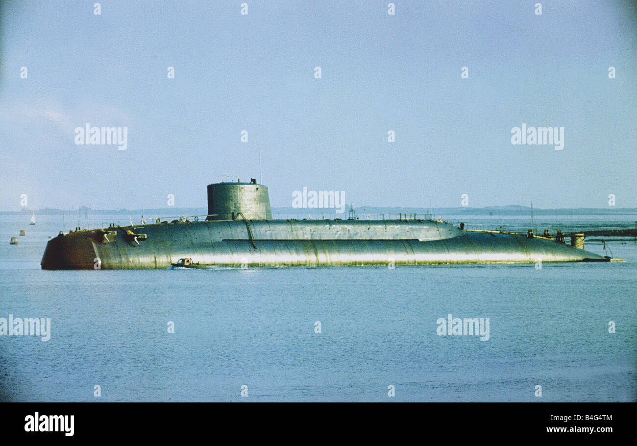
                Welcome to the discussion. Great pic you found there. That is indeed Repulse, soon after she had been launched in fact. The launch was held up (waiting for the wife of one of the dignitaries to arrive), and because Repulse missed her tidal window she ended stuck on the bottom. They tried using tugs to drag into deeper water but she wouldn't move, so there she sat on the mud until the next high tide. The embarrassing situation was the first time in the Barrow shipbuilding yards history that a vessel failed to launch successfully. The story made the national news papers. The pic is very interesting because it confirms that these submarines were launched without rudders and without prop fitted. This pic demonstrates exactly why. I have been to see the old slipways - which still exist, but are no longer used because they now roll out new subs on rails and they are gently lowered down into the water using a specially built lift (elevator). But yeah the old slipway delivered the launched vessel at an angle into narrow channel - which was also tidal! Also the pic shows very nicely the profile of the stern part of the hull. It's very curvy and bullet shaped. Thanks for posting your pic find.

                Best regards
                Steve.

                Comment

                • steveuk
                  Junior Member
                  • Oct 2005
                  • 467

                  #23
                  Hi Ralph,
                  Welcome to the discussion. Great pic you found there. That is indeed Repulse, soon after she had been launched in fact. The launch was held up (waiting for the wife of one of the dignitaries to arrive), and because Repulse missed her tidal window she ended stuck on the bottom. They tried using tugs to drag into deeper water but she wouldn't move, so there she sat on the mud until the next high tide. The embarrassing situation was the first time in the Barrow shipbuilding yards history that a vessel failed to launch successfully. The story made the national news papers. The pic is very interesting because it confirms that these submarines were launched without rudders and without prop fitted. This pic demonstrates exactly why. I have been to see the old slipways - which still exist, but are no longer used because they now roll out new subs on rails and they are gently lowered down into the water using a specially built lift (elevator). But yeah the old slipway delivered the launched vessel at an angle into narrow channel - which was also tidal! Also the pic shows very nicely the profile of the stern part of the hull. It's very curvy and bullet shaped. Thanks for posting your pic find.

                  Best regards
                  Steve.
                  Attached Files

                  Comment

                  • Davidh
                    Junior Member
                    • Feb 2016
                    • 74

                    #24
                    Hi Steve,

                    I didn't get that email.

                    Try. d.hughes@maitlandcs.nsw.edu.au. Dave is fine.

                    Ralph,

                    Awesome pic, any more!

                    David h

                    Comment

                    • Ralph --- SSBN 598
                      Junior Member
                      • Oct 2012
                      • 1417

                      #25
                      That was just a 5 minute google search and the pick of the best profile i saw.
                      Took me a minute to realize the boat was stranded on a sand bar.
                      With the water at mid hull is nice doe detail below waterline.

                      Comment

                      • salmon
                        Treasurer
                        • Jul 2011
                        • 2342

                        #26
                        Steve,
                        When will you and Ron have this ready for market? Have you thought of a price range for it?
                        Peace,
                        Tom
                        If you can cut, drill, saw, hit things and swear a lot, you're well on the way to building a working model sub.

                        Comment

                        • steveuk
                          Junior Member
                          • Oct 2005
                          • 467

                          #27
                          Ralph, Yeah sure is a nice picture. One of a very few which actually give a clear view of stern profile all the way down to the tail end. This actual picture wasn't on the net when I did my searches. Goes to show the net is constantly getting new stuff uploaded. - I learned something there. Did another search and got some more pics I hadn't come across before.

                          Tom, Ron has been waiting on me. Because I want this to be as right as it can be (short of having any access to any proper ships drawings - which seems to be like that's never gonna happen) it has taken me this long to get where I am. Good news is I feel the end of this build is not far away now. Main shapes are all in and I'm happy with the look. Just applying super detailing to outer surface. The tiling has proved to be a big challenge, because on Repulse the grid pattern is raised not recessed. In real life it is basically caulking applied very untidily in between all tiles. If they were recessed lines I could have scribed them in like panel lines. But this needs to be a raised grid pattern. On this model each tile works out to 3mm square! I think I finally have the solution now though. Glue is drying on my latest 'experiment'.
                          As soon as I'm done Ron will be arranging to get the model molded up professionally, and then it will be offered on his website.
                          Why you fancy a Brit sub?

                          Comment

                          • salmon
                            Treasurer
                            • Jul 2011
                            • 2342

                            #28
                            Yes I do fancy a Brit sub, Brit subs have a very unique look to them. The Resolution class is a beautiful sub.
                            Now saying that, I love subs, U.S. subs, German subs, Israeli Subs, Russian subs, Sci-Fi subs, old subs and modern. Although some modern subs seem to look alike at first glance.
                            I would want one of your subs when it is available.
                            If you can cut, drill, saw, hit things and swear a lot, you're well on the way to building a working model sub.

                            Comment

                            • wingtip
                              Member
                              • Dec 2004
                              • 335

                              #29
                              Goes to show the net is constantly getting new stuff uploaded. - I learned something there. Did another search and got some more pics I hadn't come across before
                              I noticed this a few years back while working on my lifetime project lol... but learned to go back to the net every so often and spend a few hours researching all over again and i would come up with new stuff occasionally..its great.

                              Comment

                              • steveuk
                                Junior Member
                                • Oct 2005
                                • 467

                                #30
                                Tom - You're very welcome to when they come out. Keep watching this thread to see how the progress is going. That will give you some idea of how soon these will be becoming available. I am like you, there are so many types of subs I would love to model.

                                Wingtip - I'm intrigued now..What is your lifetime project?

                                Comment

                                Working...