Portsmouth/MI limber holes for 1/72 Gato

Collapse
X
 
  • Filter
  • Time
  • Show
Clear All
new posts
  • PaulC
    Administrator
    • Feb 2003
    • 1542

    Portsmouth/MI limber holes for 1/72 Gato

    For the past nine months I've waited in vain for the aftermarket guys to produce a stencil or PE limber hole set to depict the Portsmouth plan configuration for Revell's 1/72 Gato. And so far each completed kit I've seen has depicted an Electric Boat hull (some static builds offered on eBay even claim to depict Portsmouth boats without changing the limber pattern). As I'm modeling SS-238 Wahoo, a Mare Island boat which followed the Portsmouth plans, and no one else has taken the bull by the horns, I've buckled down and started in on the task myself.

    Since the Gato kit comes with the EB limber hole pattern I figured the first step would be to take everything back to square one. This meant eliminating two problems: the row of half round holes forward, and the gap between the turtleback and the sides of the hull.

    The two pieces with the half round holes were tackled first. Tape was applied on the face of the outside of the part and Evercoat filler was applied to the hole on the backside. Once hard, the tape was removed to reveal a smooth outer side. I'll test the adhesion after an overnight cure.


    The gap along the turtleback was even easier. I took my kit parts to the LHS and found Evergreen StripStyrene in .080x.125" filled the gap perfectly. It's the right height to take the casing down to the hull and is the same wall thickness as the tutleback parts.


    I started with the aft piece. I held the strips in place with clothespins and glued them in with Tenax-7X plastic weld. The stuff works great -- no adhesion problems there.

    The mid-deck section has beveled edges on the inboard side of the hull casing. The contact point with the styrene was greatly reduced. However, the Tenax did the trick the same as the aft section. To reinforce the seam I filled the backside gap with JB Weld. A bevel was block sanded on the interior side of the styrene to create a better fit with the rounded hull.

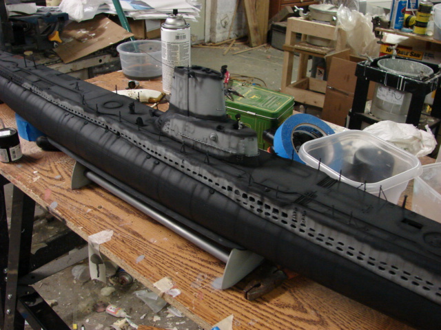
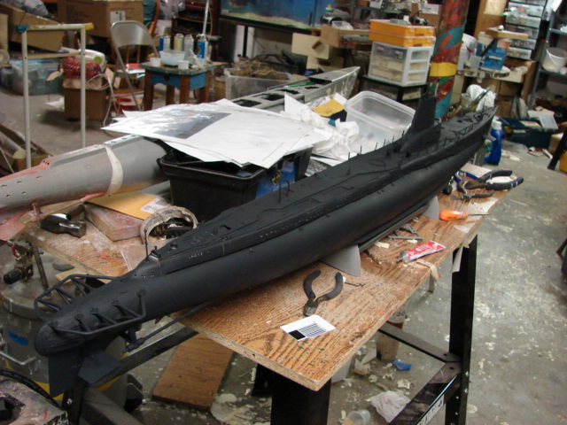
    The initial mockup looked good to me. Everything is held loosely in place but you can see how the half-rounds will disappear with primer and the turtleback deck casing now comes down to the hull.


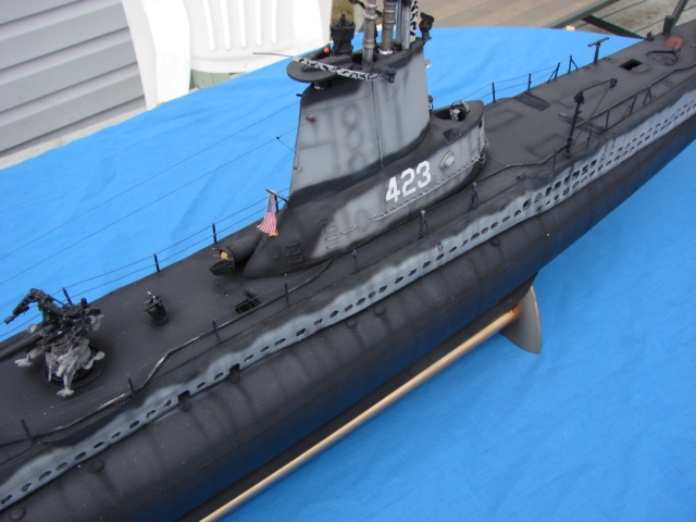
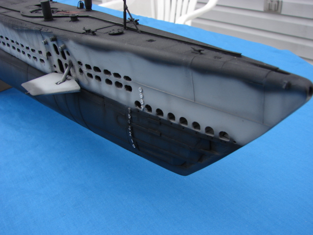
    With a blank canvas it is now time to create a stencil and map to scribe in the long row of oblong holes that distinguish the Portsmouth and Mare Island built Gatos and Balaos.
    Warm regards,

    Paul Crozier
    <><
  • cody
    Junior Member
    • Nov 2006
    • 13

    #2
    I'm going to find this

    I'm going to find this interesting.
    The thing that stops me from doing something like this...
    Re-doing the 'Limber Holes' over the previously filled holes. Cracking and chipping seem inevitable?
    Please keep this going...I will love to see the end result.


    Jeff

    Comment


    • #3
      There is a Portsmouth conversion

      There is a Portsmouth conversion in the works from one of our regular aftermarket sources. Its just a question of when.

      One thing to be careful about, the casing just aft of the bow planes was shaped very differently on Portsmouth-planned boats than on Electric Boat subs, like the Revell kit. You'll have to do some reshaping there to get the correct curvature.

      Looks good, though! I want to see more.

      Robert

      Comment

      • rustysub
        Junior Member
        • Apr 2005
        • 52

        #4
        I have been there were

        I have been there were you are. , I did mine the same way, backed a piece of styrene and filled them in with resin. That was the easy part, the hard part is what comes next from were you are. Mapping the holes and drilling them out uniformly is not an easy task. There are also many different shaped and sized holes, they also vary from boat to boat. If a generic template for PM comes, You will have to alter some holes to do a boat accurately. I used metal templates which I made and wore out for different hole sizes. I recall it was something like 5 different sizes and shapes for holes. On my boat the Torsk, I also had a another task and that swaying the rear deck inward behind the Sail. Some latter boats (Tench and Balaos) had that feature, not all just some. Just take your time in drilling and mapping. Good luck. Here are some pic's of my boat with the PM rows. Mario


        Comment

        • PaulC
          Administrator
          • Feb 2003
          • 1542

          #5
          Thanks for the encouragement, guys!

          Yes,

          Thanks for the encouragement, guys!

          Yes, cracking and chipping of the filled holes is my concern too. Will have to see how the filler holds up. However, most of the holes won't overlap the filled ones.

          There will be overlap with the strip styrene. However, it's very solidly in place and I don't expect any trouble there.

          Yes, the superstructure does curve differently leading into the bow planes. While you and I will know it's wrong, Robert, most people won't. And I'm kinda in a hurry with this one so I'm going to let it slide. I'll correct it on my next Gato project however.

          Which outfit is working on the Portsmouth aftermarket set? Please email or PM me!

          Yes, the templates are next and I'm going to go the same route you did, Mario: brass templates. Not counting muffler exhausts, I'm only seeing two distinct sizes of oblong limber holes on my Wahoo docking plans. Very nice looking boat by the way!

          Anyone altered their conning tower fairwater aft end into a point yet?
          Warm regards,

          Paul Crozier
          <><

          Comment

          • rustysub
            Junior Member
            • Apr 2005
            • 52

            #6
            Hi Paul, Thank you for

            Hi Paul, Thank you for your kind words. I am pretty sure you are in luck with the section mentioned that bows inward aft the plane crevices, I did research a Wahoo for 1/178 model thats posted on modelwarships gallery. Its was an early Mare Island Gato, For anyone reading, The section discussed is a triangular shape welded/crimped plating that cuts inward behind the Plane crevice frames. Its common on PM Balaos and Tenches. If you look at this picture I added this rear feature to the rear of the planes by masking the shape and using a dremel with drum I cleaned inward. Latter I replated the area with rivet panel that I made in conjunction with rivet panels for the entire upper structure behind the planes to stern. So if it has to be done, it could. Back to the Wahoo, The lines on the Nav source Wahoo pictures are pretty much straight back. No indentation of this Triangle. This works in your favor. I don't believe those boats had that. About the tower you are right you will need to curve the tower inward on the back. Hope this helps, Mario http://www.navsource.org/archives/08/0823832.jpg

            Comment

            • bob_eissler
              SubCommittee Member
              • Aug 2005
              • 331

              #7
              Just a thought, but I

              Just a thought, but I bought the Eduard photoetch pieces this weekend and they are very nice. Wouldn't it be easier to make correct photoetch panels, carve out the platic & overlay the photoetch? Sounds a lot easier than shaping all the holes in plastic.

              Comment

              • PaulC
                Administrator
                • Feb 2003
                • 1542

                #8
                Bob,

                If an aftermarket PE set

                Bob,

                If an aftermarket PE set for the Portsmouth holes were available, then yes. But I can mark and file holes faster than designing and etching my own set of PE parts.

                If Eduard made a set for the Portsmouth boats I'd be all over it. Their EB set looks exceptional.
                Warm regards,

                Paul Crozier
                <><

                Comment

                • PaulC
                  Administrator
                  • Feb 2003
                  • 1542

                  #9
                  In testing the cured Evercoat

                  In testing the cured Evercoat in the half round holes I found that everything holds up well. Granted I'm doing a static build. But it seems pretty stout to me.
                  Warm regards,

                  Paul Crozier
                  <><

                  Comment

                  Working...
                  X