Attention all registered users. The new forum upgrade requires you to reset your password as you logon for the first time.
To reset your password choose this option that is displayed when you attempted to login with your username: "Forgotten your password? Click here!"
You will be sent an e-mail to the address that is associated with your forum account. Follow the simple directions to reset your password.
If this is your first visit, be sure to
check out the FAQ by clicking the
link above. You may have to register
before you can post: click the register link above to proceed. To start viewing messages,
select the forum that you want to visit from the selection below.
How do you handle pushrod (rudder, planes) binding? The servo arm moves in an arc while the pushrod should have a linear motion through its WTC end cap seal (i.e. the Sub-Tech U-cup type). What is the common practice?
Thanks.
Are you referring to the pushrod actually binding or how to ensure that the pushrod moves through the WTC bulkhead seal in a purely linear motion? The two are very different.
For push rods, I use a piece of brass tubing on the inside of the cylinder cap used as a bushing for the 1/8" push rod/tubing.
I solder 1/16" brass rod in both ends of the tubing so I can put connectors or Z bends to control horns or servo horns.
The 1/16" rod will bends enough to account for the servo ark if I center the rod tot he center of the control horn ark.
I have also used cable soldered in to the control tubing on the inside part which will flex.
I try to place the servos so there is a long distance from servo to cap seal/bushing so the amount of bend is minimal.
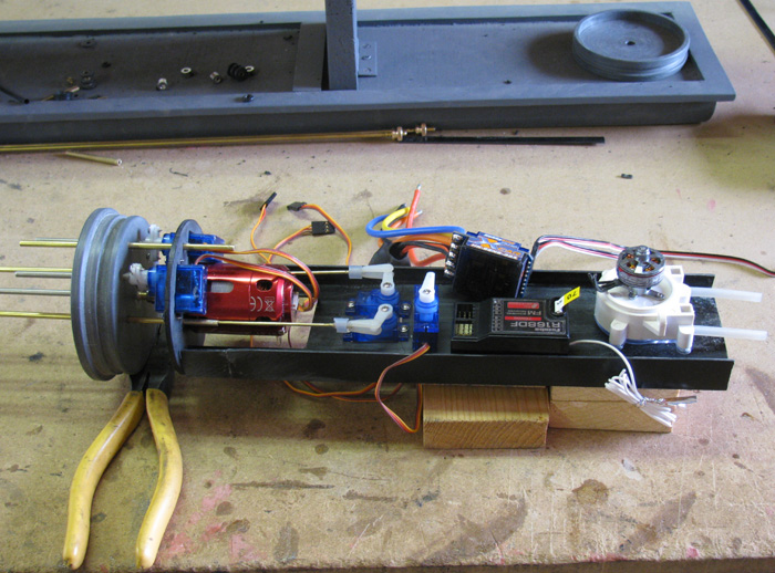
In the photo below, you can see the control bushing tub which goes from the cap in about 1 1/2".
The bushing is fixed to the cap and is held in place by tight hole in the motor mount bulk head.
The end going to the servo is 1/16" brass rod which is about 3" long before reaching the 1/8" tube.
All the torque on the push rod is supported by the bushing tube that the 1/8" tubing goes through and not the O-ring seal.
I am going to speak gossip here, a friend in CA told me that the units that attach to the top had a high failure rate when he experimented with them. He is widely known as The Architect and his piston WTCs are some of the most beautiful I have seen.
Maybe others have had good experiences with them and if so, ignore my past statement.
What are 90% (a totally bogus number on my part - could be higher, I doubt lower) of us using in our WTC regarding push rods?
A higher percentage are using regular servos, not the linear ones. So what about the flex? Well, there will be a little but placing a bend in the push rod so it exits out straight in the neutral position (minimizing the affect of flexing). I have seen a finer wire used on the servo connecting to a larger diameter to absorb the flex while still providing good push/pull qualities too.
If it is binding and not linear, what seals are you using? or can you show us what you have and what is going on?
I can throw out things like using silicon grease, but if you have silicon seals, I would be giving bad advice.
If you can cut, drill, saw, hit things and swear a lot, you're well on the way to building a working model sub.
My current preference is to use the bellows-style that OTW includes with their dive modules. They deal with the servo side-to-side movement without any trouble.
List of parts: wheel collar to fit the pushrod; piece of flex cable (Dubro 165); and a solder on clevis Silver solder a short piece of the flex cable to a notch filed in the wheel collar. Silver solder a clevis onto the flex cable. The pictures are of the WTC for my Trumpeter 1:144 scale USS SEAWOLF.
My thanks to all of you for your answers and suggestions; this is one of the things that makes this group so great. Any suggestions as to where I can buy bellows for 1/8" dia. pushrods?
Thanks.
What I have been doing is similar to what the others are doing.
But I use a 1/32" brass rod soldered into a hole drilled in the end of the 1/8" linkage.
The 1/32" flexes very easily to cope with the servo arc and is strong enough to do its job.
But under extreme binding will act as a servo saver and bend the rod before damaging the servo.
I have tried many different ways to do it but this seems to work the best for me.
Like many things in model submarines there is no right way or wrong way. Just the way you like as long as it works. BD.
sigpic"Eat your pudding Mr Land"
"I ain't sure it's pudden" 20K
A bend in the control rod is to align the rod going through the seal and the servo arm when the servo can not be place with the center of the servo sweep centered tot he seal.
Also a bend will act like shock absorber and flex more than a straight rod.
I put the bends in the tail cone after exiting the cylinder.
I think this keeps the inside of the cylinder less cluttered and I have access to the bend while in the field by just opening up the hull access.
I don't have to open the cylinder to rebend the rod.


Comment